EP0564372A1 - Offsetdruckmaschine - Google Patents
Offsetdruckmaschine Download PDFInfo
- Publication number
- EP0564372A1 EP0564372A1 EP93400869A EP93400869A EP0564372A1 EP 0564372 A1 EP0564372 A1 EP 0564372A1 EP 93400869 A EP93400869 A EP 93400869A EP 93400869 A EP93400869 A EP 93400869A EP 0564372 A1 EP0564372 A1 EP 0564372A1
- Authority
- EP
- European Patent Office
- Prior art keywords
- cylinder
- axis
- plate cylinder
- sleeve
- bearings
- Prior art date
- Legal status (The legal status is an assumption and is not a legal conclusion. Google has not performed a legal analysis and makes no representation as to the accuracy of the status listed.)
- Granted
Links
- 238000007645 offset printing Methods 0.000 title abstract description 9
- 238000007639 printing Methods 0.000 claims abstract description 25
- 238000006073 displacement reaction Methods 0.000 description 4
- 230000006835 compression Effects 0.000 description 2
- 238000007906 compression Methods 0.000 description 2
- 238000000151 deposition Methods 0.000 description 1
- 239000010410 layer Substances 0.000 description 1
- 239000000314 lubricant Substances 0.000 description 1
- 239000000463 material Substances 0.000 description 1
- 230000002093 peripheral effect Effects 0.000 description 1
- 239000002344 surface layer Substances 0.000 description 1
Images


Classifications
-
- B—PERFORMING OPERATIONS; TRANSPORTING
- B41—PRINTING; LINING MACHINES; TYPEWRITERS; STAMPS
- B41F—PRINTING MACHINES OR PRESSES
- B41F13/00—Common details of rotary presses or machines
- B41F13/44—Arrangements to accommodate interchangeable cylinders of different sizes to enable machine to print on areas of different sizes
-
- B—PERFORMING OPERATIONS; TRANSPORTING
- B41—PRINTING; LINING MACHINES; TYPEWRITERS; STAMPS
- B41F—PRINTING MACHINES OR PRESSES
- B41F13/00—Common details of rotary presses or machines
- B41F13/08—Cylinders
- B41F13/24—Cylinder-tripping devices; Cylinder-impression adjustments
- B41F13/26—Arrangement of cylinder bearings
- B41F13/28—Bearings mounted eccentrically of the cylinder axis
Definitions
- the present invention relates to an offset printing apparatus.
- Offset printing machines generally include a plate cylinder tangent to a blanket cylinder, with a flexible surface layer, which transfers a layer of ink onto a sheet of printing material traveling between the blanket cylinder and a counterpart cylinder applied under pressure. against the previous one, this counterpart cylinder can be constituted by a blanket cylinder in the case of a double-sided printing on the web.
- the plate cylinder and the blanket cylinder are mounted between the two lateral flanges of a removable cassette that can be moved transversely relative to the printing apparatus, that is to say perpendicular to the direction of travel. of the tablecloth to print.
- the various settings necessary for printing are obtained by setting the cylinders either with the aid of eccentrics or by applying the cylinders to sloping wedges.
- the setting between the plate cylinder and the blanket cylinder is carried out by a displacement of the blanket cylinder
- biasing that is to say the small relative inclination of the axes of the plate and blanket cylinders
- the timing between the blanket cylinder and the counter cylinder (or other blanket cylinder) is achieved by the displacement of the counter cylinder.
- the blanket cylinder must be as rigid as possible and to do this we must produce, with a view to moving the blanket cylinder, eccentrics having clearances of a few micrometers and most often with a supply of a lubricant under pressure in order to have a relatively easy operation and minimal wear over time.
- This type of solution is therefore relatively expensive to have a correct printing function.
- the present invention aims to remedy this drawback by providing an offset printing device of the removable cassette type with a reduced overall cost due to a great simplification of its assembly.
- this offset printing apparatus comprising a frame in which a removable cassette can be mounted carrying a plate cylinder and a blanket cylinder with axes parallel and tangent to one another, a tablecloth to be printed scrolling between the blanket cylinder and a counter cylinder, mounted movably on the frame of the apparatus and which can be applied against the blanket cylinder, the plate and blanket cylinders being engaged in front bearings and in rear bearings carried respectively by front flanges and rear of the cassette, is characterized in that the bearings of the blanket cylinder are fixedly mounted on the flanges of the cassette, in that the bearings of the plate cylinder include means for adjusting the position of the axis of the plate cylinder and in that each of the front and rear flanges of the cassette carries a connection mechanism between mobile control means of the printing apparatus and the means for adjusting the bearings of the plate cylinder, to adjust the position of the axis of this cylinder according to the printing conditions required.
- Figure 1 is a schematic elevational view, partially broken away, of an offset printing apparatus according to the invention.
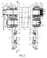
- FIG. 2 is a view in vertical and transverse section (relative to the ply), on a larger scale, taken along line II-II of FIG. 1.
- FIG. 3 is a sectional view, vertical and longitudinal (with respect to the sheet), taken along line III-III of FIG. 2.
- Figure 4 is an elevational view (taken from the right in Figure 2) of the front flange of the removable cassette.
- the offset printing apparatus which is shown in a simplified form in Figure 1, comprises a frame 1 consisting essentially of longitudinal and vertical uprights, parallel to each other, connected by cross members not shown and between which s' extend horizontally and transversely the different cylinders of the printing apparatus.
- the term “longitudinal” means parallel to the direction of travel of a web 2 to be printed passing through the apparatus, while the term “transverse” means "horizontal and perpendicular to the direction of travel of the web” or else "perpendicular to the plane of the drawing figure".
- the cylinders of the apparatus can be arranged vertically, being superimposed on each other, as shown in the drawing, or even horizontally or according to any other arrangement.
- this apparatus comprises an upper touch cylinder 3, mounted for rotation on the frame 1 of the apparatus and depositing a film of ink on a cylinder plate holder 4 arranged below it.
- This plate cylinder 4 is tangent to a lower blanket cylinder 5 and is mounted, together with this blanket cylinder 5, on a removable cassette 6.
- This cassette 6 essentially comprises two lateral, vertical and longitudinal flanges, namely a front flange 7 and a rear flange 8 braced by suitable horizontal crosspieces, not shown.
- the two flanges 7,8 constitute supports for respective shafts 9,10 of the plate 4 and blanket 5 cylinders 5.
- the assembly of the cassette 6 can be pulled, in the horizontal and transverse direction, outside the frame 1 of the printing device and set place inside this frame 1, for example by passing through an opening 1 a provided in the front upright of the frame 1.
- the printing apparatus comprises a counterpart cylinder 11, of axis transverse. It should be noted that, in certain devices allowing double-sided printing on the web 2, the counterpart cylinder 11 also constitutes a second blanket cylinder.
- the impression cylinder 11 is carried by a movable element vertically so as to be able to occupy a lowermost position indicated in phantom in Figure 1 and in which it is retracted below the lower edge of the opening 1a of the frame 1. In this retracted position the counterpart cylinder 11 allows the cassette 6 to be removed from the outside of the printing apparatus and reintroduced therein by a movement in the transverse direction. On the other hand, in the printing position, it is in the high position, as shown in FIG. 1, and it is tangent to the lower part of the blanket cylinder 5, the sheet to be printed 2 then being clamped between the two cylinders 5 and 11.
- the mobile assembly carrying the counterpart cylinder 11 can be constituted, for example, by a support oscillating around an axis 11a.
- the shaft 9 of the plate cylinder 4 is extended at its ends by front pins 9a and rear 9b housed respectively in front bearings 12 and rear 12a.
- the shaft 10 of the blanket cylinder 5 is extended at its ends by front pins 10a and rear 10b housed respectively in front bearings 13 and rear 13a.
- the two bearings 13, 13a supporting the shaft 10 of the blanket cylinder 5 are fixedly mounted respectively on the front flanges 7 and rear 8 of the cassette 6, while the bearings 12,12a supporting the shaft 9 of plate cylinder 4 are mounted adjustable on these flanges.
- each of the bearings 12, 12a of the shaft 9 comprises a bearing 14, for example with needles, in which the corresponding pin 9a, 9b is engaged and which is housed in an eccentric bore of a sleeve 15.
- This sleeve 15 is fixed at one end, by means of screws 16, to an operating collar 17 situated, for example, on the internal side of the corresponding flange 7.8. Because the bore of the sleeve 15 which receives the bearing 14, is eccentric relative to the axis of this sleeve 15, a rotation of the sleeve 15 about its axis causes a vertical displacement of the axis of the bearing 14, c that is to say of the shaft 9 of the plate cylinder 4.
- the assembly constituted by the sleeve 15 and its operating collar 17 will be considered subsequently as constituting an eccentric.
- the control of the rotational movement of this eccentric is carried out, on each of the flanges 7,8, by the same connection mechanism and we will now describe only, with particular reference to Figures 1 and 3, the connection mechanism 18 which is mounted on the rear flange 8 of the cassette and which controls the adjustment of the rear bearing 12a.
- This mechanism includes a vertical bar 19 which is mounted vertically movable and which extends close to the internal face of the rear flange 8, along one of its vertical edges.
- This operating bar 19 is designed to be actuated, at its lower end, by a control device provided on the frame of the printing apparatus, in order to lift it.
- the bar 19 may have, in its lower end portion, a notch 20 which can be coupled with an operating member forming part of the control device.
- the bar 19 is returned to the lower extreme position by a tension spring 21 which extends vertically and which is hooked, at its upper end, to a finger 22 secured to the bar 19 and, at its lower end, to a finger 23 fixed to the flange 8.
- This finger 23 is engaged through an oblong vertical slot 24 pierced in the bar 19, in order to limit the vertical movement of the latter.
- the operating bar 19 is articulated around an axis 25, on the end of a branch of a bent return lever 26 pivotally mounted on the flange 8, around a horizontal axis and transverse 27.
- the other branch of the bent lever 26 is articulated, about an axis 28, on one end of a substantially horizontal rod 29 whose other end is articulated, around an axis 31, on the lower part of the collar 17 forming part of the eccentric 15-17.
- the vertical operating bar 18 is shown in the extreme upper position in which it is raised by the control device of the printing apparatus and this position corresponds to a position of the eccentric 15-17 for which the axis from the landing 12a and consequently of the shaft 9 is in the extreme lower position.
- the operating bar 18 is no longer held raised, it is returned downwards by its return spring 21, which causes a rotation of the eccentric 15-17 and an offset of the axis of the bearing 14 and tree 9 upwards.
- the upper extreme position of the operating bar 19 and consequently the extreme rotational position of the eccentric 15-17 are determined by an adjustable stop 32 with adjusting screw 33.
- This adjustable stop 32 which determines the position set in pressure, is fixed on the internal face of the flange 8 and the adjusting screw is mounted in this stop so that its end is in contact with a bearing surface 34 provided in the lower part of the flange 17.
- One of the bearings of the shaft 9 of the plate cylinder 4, in the example described the front bearing 12, is furthermore somewhat adjustable in the horizontal and longitudinal direction, in order to allow adjustment of the bias between the two.
- cylinders 4 and 5 that is to say of the mutual inclination, in a horizontal plane, of their respective axes.
- the sleeve 15 of the eccentric 15-17 of the bearing 12a is itself housed in a second bearing 35, for example with needles, disposed inside an eccentric bore of a second sleeve 36 mounted at rotation, about its axis, in the front flange 7 by means of a third bearing 37.
- the sleeve 36 with an eccentric bore is integral with the outside of the front flange 7, of a flange 38 carrying an operating pin 39. Consequently, when the second sleeve 36 is rotated, the first movement is caused to move horizontally, in one direction or the other sleeve 15 and the journal 9a of the shaft 9, which thus makes it possible to adjust the bias of this shaft relative to the shaft 10 of the blanket cylinder 5.
- the two 4.5 rotating cylinders are driven at the rear of the device.
- the rear pins 9b, 10b of the two shafts 9 and 10 are respectively secured to two pinions 41 and 42, of the same pitch diameter, engaged with one another.
- one of the pinions 41, 42 in turn engages a drive pinion, not shown, which is rotatably mounted on the frame 1 of the printing apparatus and which is rotated by a general control device of the apparatus. Therefore the two plate cylinders 4 and blanket 5 are rotated in opposite directions to each other, at the same peripheral speed.
- the shaft 9 of the plate cylinder 4 is also mounted so that it can slide transversely to allow lateral adjustment of the plate plate that the cylinder 4 carries.
- the front journal 9a of the shaft 9 is subjected to the action of a compression spring 43 tending to push the shaft 9 towards the rear flange 8.
- This compression spring may advantageously consist of a stack of Belleville washers contained in a casing 44.
- the rear pin 9b of the shaft 9 is housed in rotation, by means of a bearing 45, in a thrust bearing 46 mounted at sliding in an opening of a casing 47 fixed outside the rear flange 8.
- the thrust bearing 46 is intended to cooperate with a movable adjustment arm, not shown, provided at the rear of the device. This arm therefore allows, by sliding more or less the thrust bearing 46 in the opening of the housing 47, to more or less push the shaft 9 forward and thus adjust the plate in the lateral direction.
Landscapes
- Engineering & Computer Science (AREA)
- Mechanical Engineering (AREA)
- Rotary Presses (AREA)
Applications Claiming Priority (2)
| Application Number | Priority Date | Filing Date | Title |
|---|---|---|---|
| FR929204114A FR2689448B1 (fr) | 1992-04-03 | 1992-04-03 | Appareil d'impression offset. |
| FR9204114 | 1992-04-03 |
Publications (2)
| Publication Number | Publication Date |
|---|---|
| EP0564372A1 true EP0564372A1 (de) | 1993-10-06 |
| EP0564372B1 EP0564372B1 (de) | 1996-10-16 |
Family
ID=9428478
Family Applications (1)
| Application Number | Title | Priority Date | Filing Date |
|---|---|---|---|
| EP93400869A Expired - Lifetime EP0564372B1 (de) | 1992-04-03 | 1993-04-02 | Offsetdruckmaschine |
Country Status (4)
| Country | Link |
|---|---|
| US (1) | US5272974A (de) |
| EP (1) | EP0564372B1 (de) |
| DE (1) | DE69305404T2 (de) |
| FR (1) | FR2689448B1 (de) |
Families Citing this family (8)
| Publication number | Priority date | Publication date | Assignee | Title |
|---|---|---|---|---|
| US5706728A (en) * | 1996-07-30 | 1998-01-13 | Rdp Marathon Inc. | Printing apparatus |
| DE19849633A1 (de) * | 1998-10-28 | 2000-05-04 | Heidelberger Druckmasch Ag | Positioniervorrichtung in einer Druckmaschine |
| DE19943027C5 (de) * | 1998-10-28 | 2016-11-17 | Heidelberger Druckmaschinen Ag | Positioniervorrichtung in einer Druckmaschine |
| EP1935642A4 (de) * | 2005-08-30 | 2012-09-05 | Rotatek S A | Walzenkassette für halbrotationsmaschinen, die in offsetdruckwerke eingeführt werden können |
| JP4878854B2 (ja) * | 2006-01-31 | 2012-02-15 | 三菱重工印刷紙工機械株式会社 | 印刷機 |
| EP1950037A3 (de) * | 2007-01-25 | 2009-12-23 | Komori Corporation | Überschalt-Verarbeitungsverfahren und Vorrichtung |
| US20110132216A1 (en) * | 2009-12-09 | 2011-06-09 | 7242514 Canada Inc. | Stack angle compensation arrangement for a skewing adjustment system in an offset printing press |
| KR101579651B1 (ko) * | 2012-11-06 | 2015-12-22 | 주식회사 엘지화학 | 롤 프린팅 장치 및 이를 이용한 롤 프린팅 방법 |
Citations (2)
| Publication number | Priority date | Publication date | Assignee | Title |
|---|---|---|---|---|
| FR2391073A1 (fr) * | 1977-05-17 | 1978-12-15 | Polygraph Leipzig | Dispositif pour le reglage diagonal des cylindres porte-cliches en particulier d'une machine a imprimer rotative a bobines |
| EP0095423A1 (de) * | 1982-05-25 | 1983-11-30 | MACHINES CHAMBON Société anonyme dite: | Offset-Druckapparat für verschiedene Formate |
Family Cites Families (7)
| Publication number | Priority date | Publication date | Assignee | Title |
|---|---|---|---|---|
| US913119A (en) * | 1908-03-23 | 1909-02-23 | Fuchs And Lang Mfg Company | Throw-out mechanism. |
| US1231932A (en) * | 1914-05-15 | 1917-07-03 | Corp Of Maschinenfabrik Johannisberg G M B H | Rotary printing or embossing machine. |
| US1330793A (en) * | 1916-04-04 | 1920-02-17 | Gustav A Friess | Cylinder-adjusting mechanism for printing-presses |
| US1816796A (en) * | 1930-01-16 | 1931-07-28 | Firm Rock Stroh Werke Ag | Rotary offset printing machine |
| DE1436541A1 (de) * | 1964-04-02 | 1969-02-06 | Roland Offsetmaschf | Rollenrotations-Druckmaschine |
| US4458590A (en) * | 1982-09-30 | 1984-07-10 | Harris Graphics Corporation | Printing press with plate cylinder skew and throw off |
| US5186103A (en) * | 1992-06-12 | 1993-02-16 | Man Roland Druckmaschinen Ag | Printing machine system, especially for printing on a web of heavy or thick stock material, with interchangeable printing cylinders |
-
1992
- 1992-04-03 FR FR929204114A patent/FR2689448B1/fr not_active Expired - Fee Related
-
1993
- 1993-04-01 US US08/041,482 patent/US5272974A/en not_active Expired - Fee Related
- 1993-04-02 DE DE69305404T patent/DE69305404T2/de not_active Expired - Fee Related
- 1993-04-02 EP EP93400869A patent/EP0564372B1/de not_active Expired - Lifetime
Patent Citations (2)
| Publication number | Priority date | Publication date | Assignee | Title |
|---|---|---|---|---|
| FR2391073A1 (fr) * | 1977-05-17 | 1978-12-15 | Polygraph Leipzig | Dispositif pour le reglage diagonal des cylindres porte-cliches en particulier d'une machine a imprimer rotative a bobines |
| EP0095423A1 (de) * | 1982-05-25 | 1983-11-30 | MACHINES CHAMBON Société anonyme dite: | Offset-Druckapparat für verschiedene Formate |
Also Published As
| Publication number | Publication date |
|---|---|
| DE69305404D1 (de) | 1996-11-21 |
| FR2689448A1 (fr) | 1993-10-08 |
| EP0564372B1 (de) | 1996-10-16 |
| DE69305404T2 (de) | 1997-05-15 |
| FR2689448B1 (fr) | 1994-06-24 |
| US5272974A (en) | 1993-12-28 |
Similar Documents
| Publication | Publication Date | Title |
|---|---|---|
| EP0095423B1 (de) | Offset-Druckapparat für verschiedene Formate | |
| EP0390689B1 (de) | Rotierende Schneidvorrichtung | |
| EP0853527B1 (de) | Mess-und regelgerät für die bearbeitung von umlaufenden zylindrischen werkstücken | |
| EP0611240B1 (de) | Druckmaschine mit mindestens einem Zylinder mit doppeltem Verfahrweg | |
| EP0177391B1 (de) | Siebdruckmaschine | |
| EP0329237A1 (de) | Siebdruckmaschine | |
| EP0564372B1 (de) | Offsetdruckmaschine | |
| EP0305230A1 (de) | Periodische Papierbahnzufuhr einer Maschine, insbesondere für eine blattabschneidende Presse | |
| FR2743548A1 (fr) | Mecanisme a elements aspirants tracteurs, en particulier pour un dispositif de correction de l'obliquite de feuilles | |
| FR2557504A1 (fr) | Dispositif de retournement de papier pour impression verso-recto | |
| CH630291A5 (fr) | Imprimeuse rotative pour l'impression en plusieurs couleurs sur des feuilles debitees d'une maniere continue. | |
| CH632022A5 (fr) | Machine a tisser avec dispositif evitant les differences de duitage au demarrage de la machine. | |
| CH670989A5 (de) | ||
| CH689717A5 (fr) | Dispositif de positionnement d'un cliché flexible sur un cylindre porte-cliché. | |
| FR2726787A1 (fr) | Dispositif de support d'une racle a cavite pour un groupe d'encrage d'une rotative d'impression | |
| EP0260178B1 (de) | Druckmaschine für den Druck auf eine konvexe Oberfläche | |
| FR2647386A1 (fr) | Dispositif de tracage et de coupe partielle en epaisseur d'un complexe multicouche adhesif protege et machine en faisant application | |
| EP0195727B1 (de) | Farbwerk mit individuell einstellbaren Dosierelementen | |
| EP0611187B1 (de) | Rotierende Schneidvorrichtung | |
| EP0564360B1 (de) | Offsetdruckmaschine | |
| EP0730954A1 (de) | Siebdruckmaschine mit wechselbarer Rakel | |
| EP0429317B1 (de) | Druckmaschine mit gesteuerter Hebevorrichtung für die Druckeinheit | |
| FR2490532A1 (fr) | Dispositif destine a arrondir les coins de plaques de verre | |
| EP0081614B1 (de) | Siebdruckmaschine mit einer von einem Elektromagnet betätigten Vorrichtung zum Absenken der Rakel | |
| LU82643A1 (fr) | Dispositif de reglage d'un encrier pour une imprimeuse rotative offset |
Legal Events
| Date | Code | Title | Description |
|---|---|---|---|
| PUAI | Public reference made under article 153(3) epc to a published international application that has entered the european phase |
Free format text: ORIGINAL CODE: 0009012 |
|
| AK | Designated contracting states |
Kind code of ref document: A1 Designated state(s): CH DE GB IT LI NL SE |
|
| 17P | Request for examination filed |
Effective date: 19940323 |
|
| 17Q | First examination report despatched |
Effective date: 19951006 |
|
| GRAH | Despatch of communication of intention to grant a patent |
Free format text: ORIGINAL CODE: EPIDOS IGRA |
|
| GRAH | Despatch of communication of intention to grant a patent |
Free format text: ORIGINAL CODE: EPIDOS IGRA |
|
| GRAH | Despatch of communication of intention to grant a patent |
Free format text: ORIGINAL CODE: EPIDOS IGRA |
|
| GRAH | Despatch of communication of intention to grant a patent |
Free format text: ORIGINAL CODE: EPIDOS IGRA |
|
| GRAA | (expected) grant |
Free format text: ORIGINAL CODE: 0009210 |
|
| AK | Designated contracting states |
Kind code of ref document: B1 Designated state(s): CH DE GB IT LI NL SE |
|
| REF | Corresponds to: |
Ref document number: 69305404 Country of ref document: DE Date of ref document: 19961121 |
|
| ITF | It: translation for a ep patent filed | ||
| GBT | Gb: translation of ep patent filed (gb section 77(6)(a)/1977) |
Effective date: 19970115 |
|
| PLBE | No opposition filed within time limit |
Free format text: ORIGINAL CODE: 0009261 |
|
| STAA | Information on the status of an ep patent application or granted ep patent |
Free format text: STATUS: NO OPPOSITION FILED WITHIN TIME LIMIT |
|
| 26N | No opposition filed | ||
| PGFP | Annual fee paid to national office [announced via postgrant information from national office to epo] |
Ref country code: GB Payment date: 20010316 Year of fee payment: 9 |
|
| PGFP | Annual fee paid to national office [announced via postgrant information from national office to epo] |
Ref country code: NL Payment date: 20010329 Year of fee payment: 9 |
|
| PGFP | Annual fee paid to national office [announced via postgrant information from national office to epo] |
Ref country code: SE Payment date: 20010402 Year of fee payment: 9 |
|
| REG | Reference to a national code |
Ref country code: GB Ref legal event code: IF02 |
|
| PG25 | Lapsed in a contracting state [announced via postgrant information from national office to epo] |
Ref country code: GB Free format text: LAPSE BECAUSE OF NON-PAYMENT OF DUE FEES Effective date: 20020402 |
|
| PG25 | Lapsed in a contracting state [announced via postgrant information from national office to epo] |
Ref country code: SE Free format text: LAPSE BECAUSE OF NON-PAYMENT OF DUE FEES Effective date: 20020403 |
|
| PG25 | Lapsed in a contracting state [announced via postgrant information from national office to epo] |
Ref country code: NL Free format text: LAPSE BECAUSE OF NON-PAYMENT OF DUE FEES Effective date: 20021101 |
|
| EUG | Se: european patent has lapsed |
Ref document number: 93400869.9 |
|
| GBPC | Gb: european patent ceased through non-payment of renewal fee |
Effective date: 20020402 |
|
| NLV4 | Nl: lapsed or anulled due to non-payment of the annual fee |
Effective date: 20021101 |
|
| PG25 | Lapsed in a contracting state [announced via postgrant information from national office to epo] |
Ref country code: IT Free format text: LAPSE BECAUSE OF NON-PAYMENT OF DUE FEES;WARNING: LAPSES OF ITALIAN PATENTS WITH EFFECTIVE DATE BEFORE 2007 MAY HAVE OCCURRED AT ANY TIME BEFORE 2007. THE CORRECT EFFECTIVE DATE MAY BE DIFFERENT FROM THE ONE RECORDED. Effective date: 20050402 |
|
| PGFP | Annual fee paid to national office [announced via postgrant information from national office to epo] |
Ref country code: CH Payment date: 20070413 Year of fee payment: 15 |
|
| PGFP | Annual fee paid to national office [announced via postgrant information from national office to epo] |
Ref country code: DE Payment date: 20070423 Year of fee payment: 15 |
|
| REG | Reference to a national code |
Ref country code: CH Ref legal event code: PL |
|
| PG25 | Lapsed in a contracting state [announced via postgrant information from national office to epo] |
Ref country code: LI Free format text: LAPSE BECAUSE OF NON-PAYMENT OF DUE FEES Effective date: 20080430 Ref country code: DE Free format text: LAPSE BECAUSE OF NON-PAYMENT OF DUE FEES Effective date: 20081101 Ref country code: CH Free format text: LAPSE BECAUSE OF NON-PAYMENT OF DUE FEES Effective date: 20080430 |