EP0564785A1 - Dispositif à usiner les extrémités de tubes - Google Patents
Dispositif à usiner les extrémités de tubes Download PDFInfo
- Publication number
- EP0564785A1 EP0564785A1 EP93102198A EP93102198A EP0564785A1 EP 0564785 A1 EP0564785 A1 EP 0564785A1 EP 93102198 A EP93102198 A EP 93102198A EP 93102198 A EP93102198 A EP 93102198A EP 0564785 A1 EP0564785 A1 EP 0564785A1
- Authority
- EP
- European Patent Office
- Prior art keywords
- clamping
- tool
- handwheel
- spindle
- housing
- Prior art date
- Legal status (The legal status is an assumption and is not a legal conclusion. Google has not performed a legal analysis and makes no representation as to the accuracy of the status listed.)
- Granted
Links
- 238000003801 milling Methods 0.000 claims abstract description 4
- 238000003754 machining Methods 0.000 abstract description 4
- 244000089486 Phragmites australis subsp australis Species 0.000 description 2
- 238000006073 displacement reaction Methods 0.000 description 1
- 230000002349 favourable effect Effects 0.000 description 1
- 230000005484 gravity Effects 0.000 description 1
- 238000004519 manufacturing process Methods 0.000 description 1
- 230000013011 mating Effects 0.000 description 1
- 230000000284 resting effect Effects 0.000 description 1
Images

Classifications
-
- B—PERFORMING OPERATIONS; TRANSPORTING
- B23—MACHINE TOOLS; METAL-WORKING NOT OTHERWISE PROVIDED FOR
- B23B—TURNING; BORING
- B23B5/00—Turning-machines or devices specially adapted for particular work; Accessories specially adapted therefor
- B23B5/16—Turning-machines or devices specially adapted for particular work; Accessories specially adapted therefor for bevelling, chamfering, or deburring the ends of bars or tubes
- B23B5/161—Devices attached to the workpiece
- B23B5/163—Devices attached to the workpiece with an external clamping device
Definitions
- the invention relates to a device for processing pipe ends with a housing, which is provided with an adjustable clamping device for fixed connection of the device to the pipe to be processed, and with a tool driven by a motor, in particular a milling tool, which by means of a hand over a Handwheel adjustable feed is movable with respect to the pipe end.
- a device of the type mentioned in the form of a portable device with compressed air connections for an integrated compressed air motor is known.
- the device is fastened to the pipe to be machined by means of two clamping jaws, one of which is fixed and the other of which is adjustable on the housing of the device.
- the disadvantage here is that the device can only be adequately attached to pipes with a minimum wall thickness.
- the shape of the pipe end can change due to the clamping forces. This then leads to an eccentricity in the machining of the pipe end, for example the production of a 45 ° bevel, so that a pipe end machined in this way does not have the accuracy of the mating surfaces required for further processing.
- Clamping tools are known with which thin-walled pipes can be clamped while largely maintaining the centricity of the pipes, but such clamping tools generally have widely designed operating parts, for example in the form of levers, which is why such clamping devices can only be used sensibly where these control parts due to their position and arrangement, do not collide with other control units of the respective device or machine and therefore interfere with each other during handling.
- the invention has for its object to improve the manageability of a device suitable for processing pipe ends of different pipe wall thicknesses.
- the handwheel for adjusting the feed is arranged on the side of the clamping device facing away from the tube on the housing.
- the arrangement of the handwheel on the housing is such that mutual hindrances when the handwheel is actuated on the one hand and other operating parts of the device on the other hand are avoided.
- the handwheel is spatially separated from the operating parts of the tensioning device, so that collisions and mutual disabilities are excluded.
- the arrangement of the handwheel on the side of the tensioning device facing away from the tube results in an overall handy position of the handwheel, so that the operator of the device is able to work comfortably and thus relaxed while processing, while at the same time having a good view of the tool and the tube end.
- the handwheel is arranged on the rear of the housing facing away from the tube.
- Another embodiment provides that the rotary movement of the handwheel, preferably via an intermediate gear, is transmitted to an axially fixed feed spindle which is provided with a fine thread on which a spindle nut provided with a corresponding counter thread is arranged in a rotationally fixed manner, the Spindle nut has a radial extension for axially displacing a tool spindle carrying the tool. In this way, despite the arrangement of the handwheel which is relatively far away from the machining point, the tool spindle is fed exactly and without play.
- the radial extension is provided with an opening for the tool spindle to pass through.
- Another embodiment is characterized by a bevel gear for transmitting the drive power of the motor to the tool spindle.
- the drive source which is preferably designed as a compressed air motor, can be arranged below the housing, which leads to a favorable position of the center of gravity of the device and thus to a further improvement in its handling.
- the clamping device consists of a clamping sleeve which can be inserted between two clamping jaws and whose clamping surfaces lie flush against the circumference of the clamped pipe section.
- the uniform clamping over the tube circumference prevents eccentricities of the tube end, so that the machining accuracy considerably increased for thin-walled pipes.
- the clamping sleeve between the clamping jaws can be removed, so that the necessary clamping force is then applied exclusively through the clamping surfaces formed on the clamping jaws.
- clamping surfaces are formed on an expandable collet which is in contact with an inner cone of the clamping sleeve via a conical surface.
- the collet be axially supported on a clamping ring which is guided in an axial thread of the clamping sleeve and is provided with at least one radially protruding operating lever.
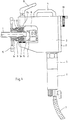
- the device shown in Fig. 1 is used to the end of a clamped tube 1 by means of a cutting tool 2 to edit.
- the tool 2 is designed as a milling tool with which the end face of the tube 1 can be machined.
- the tool 2 is guided and stored in a housing 3 which is designed to be transportable and has a carrying handle 4 on its top for this purpose.
- a cylindrical motor housing 5 with a motor 6 is flanged to the underside of the housing 3.
- the motor 6 is a compressed air motor, for the external compressed air supply of which a compressed air hose 7, which can be shut off via a valve, is provided.
- the housing 3 has a large, claw-shaped recess 8, on the upward and downward inner surfaces of which clamping jaws 9a, 9b are arranged.
- the lower jaw 9a is fixed, while the upper jaw 9b is adjustable in the direction of the lower jaw 9a.
- the adjustment takes place here by means of a hand lever 10 arranged on the upper side of the housing 3.
- An adjustable clamping device 11 for clamping thin-walled tubes is arranged between the two clamping jaws 9a, 9b and held by these.
- the clamping device 11 consists of an outer clamping sleeve 12 held by the two clamping jaws 9a, 9b, an inner collet 13 and a clamping ring 14 with two radially extending operating levers 15.
- the inner surface of the clamping sleeve 12 and the outer surface of the collet 13 are conical and lie flush with each other.
- the clamping ring 14 is provided with an external thread which engages in an internal thread of the clamping sleeve 12.
- a corrugated handwheel 18 provided with a crank. With the handwheel 18, an advance arranged in the housing 3 for the tool 2 can be adjusted by hand. Since the handwheel 18 is located on the side of the tensioning device 11 facing away from the tube 1, mutual hindrances in the operation of the tensioning wheel 18 on the one hand and the operating lever 15 of the tensioning device 11 on the other hand are excluded.
- the drive power of the compressed air motor arranged in the motor housing 5 is transmitted via a bevel gear 19 at right angles to an intermediate shaft 20 and from there via a spur gear 21 to a tool spindle 22 carrying the tool.
- the tool spindle 22 is designed to be axially displaceable.
- the feed movement initiated via the handwheel 18 is first transmitted to a feed spindle 24 via a spur gear 23.
- a spindle nut 26 provided with a corresponding counter thread is non-rotatably arranged via an axial fine thread 25.
- the spindle nut forms a kind of feed fork and for this purpose has a radial extension 27 for axially displacing the tool spindle 22 on.
- the radial extension 27 has an opening 28 for the tool spindle 22 to pass through, the radial extension 27 axially resting outside the opening 28 on axial bearings 29, which in turn are supported on shoulders of the tool spindle 22.
- the handwheel 18 via an axial displacement of the spindle nut 26 along the fine thread 25 leads to an axial movement and thus to a feed or a withdrawal of the tool relative to the pipe end.
Landscapes
- Engineering & Computer Science (AREA)
- Mechanical Engineering (AREA)
- Turning (AREA)
Applications Claiming Priority (2)
| Application Number | Priority Date | Filing Date | Title |
|---|---|---|---|
| DE9204721U | 1992-04-06 | ||
| DE9204721U DE9204721U1 (de) | 1992-04-06 | 1992-04-06 | Vorrichtung zur Bearbeitung von Rohrenden |
Publications (2)
| Publication Number | Publication Date |
|---|---|
| EP0564785A1 true EP0564785A1 (fr) | 1993-10-13 |
| EP0564785B1 EP0564785B1 (fr) | 1995-10-18 |
Family
ID=6878202
Family Applications (1)
| Application Number | Title | Priority Date | Filing Date |
|---|---|---|---|
| EP93102198A Expired - Lifetime EP0564785B1 (fr) | 1992-04-06 | 1993-02-12 | Dispositif à usiner les extrémités de tubes |
Country Status (2)
| Country | Link |
|---|---|
| EP (1) | EP0564785B1 (fr) |
| DE (2) | DE9204721U1 (fr) |
Cited By (2)
| Publication number | Priority date | Publication date | Assignee | Title |
|---|---|---|---|---|
| EP0934787A3 (fr) * | 1993-12-11 | 2003-06-25 | MASCHINENFABRIK REIKA-WERK GmbH | Dispositif de chanfreinage d' une extrémité d' un tube |
| CN110328408A (zh) * | 2019-07-11 | 2019-10-15 | 张宇 | 一种管道坡口机 |
Citations (5)
| Publication number | Priority date | Publication date | Assignee | Title |
|---|---|---|---|---|
| GB890815A (en) * | 1959-06-17 | 1962-03-07 | David Reekie & Sons Ltd | An improved machine for profiling the ends of pipes or the face of pipe flanges |
| US3131599A (en) * | 1960-01-08 | 1964-05-05 | Macfarlane George Cullen | Portable power operated chamfering tool |
| US3228268A (en) * | 1963-09-09 | 1966-01-11 | Lowry Dev Corp | Portable tube end cutting tool |
| FR2102246A1 (fr) * | 1970-08-13 | 1972-04-07 | Babcock Atlantique Sa | |
| US4655108A (en) * | 1985-09-16 | 1987-04-07 | The E. H. Wachs Company | Tube-squaring tool and clamping mechanism |
-
1992
- 1992-04-06 DE DE9204721U patent/DE9204721U1/de not_active Expired - Lifetime
-
1993
- 1993-02-12 DE DE59300765T patent/DE59300765D1/de not_active Expired - Fee Related
- 1993-02-12 EP EP93102198A patent/EP0564785B1/fr not_active Expired - Lifetime
Patent Citations (5)
| Publication number | Priority date | Publication date | Assignee | Title |
|---|---|---|---|---|
| GB890815A (en) * | 1959-06-17 | 1962-03-07 | David Reekie & Sons Ltd | An improved machine for profiling the ends of pipes or the face of pipe flanges |
| US3131599A (en) * | 1960-01-08 | 1964-05-05 | Macfarlane George Cullen | Portable power operated chamfering tool |
| US3228268A (en) * | 1963-09-09 | 1966-01-11 | Lowry Dev Corp | Portable tube end cutting tool |
| FR2102246A1 (fr) * | 1970-08-13 | 1972-04-07 | Babcock Atlantique Sa | |
| US4655108A (en) * | 1985-09-16 | 1987-04-07 | The E. H. Wachs Company | Tube-squaring tool and clamping mechanism |
Cited By (2)
| Publication number | Priority date | Publication date | Assignee | Title |
|---|---|---|---|---|
| EP0934787A3 (fr) * | 1993-12-11 | 2003-06-25 | MASCHINENFABRIK REIKA-WERK GmbH | Dispositif de chanfreinage d' une extrémité d' un tube |
| CN110328408A (zh) * | 2019-07-11 | 2019-10-15 | 张宇 | 一种管道坡口机 |
Also Published As
| Publication number | Publication date |
|---|---|
| DE59300765D1 (de) | 1995-11-23 |
| EP0564785B1 (fr) | 1995-10-18 |
| DE9204721U1 (de) | 1992-06-11 |
Similar Documents
| Publication | Publication Date | Title |
|---|---|---|
| DE3109543C2 (de) | Vorrichtung zur Kühlmittelzufuhr zu mit Kühlmittelkanälen versehenen, rotierenden Schneidwerkzeugen für die spanende Metallbearbeitung, insbesondere Bohrwerkzeugen | |
| EP0103291A1 (fr) | Tête à forer et à chanfreiner et outil à forer et à chanfreiner serré à l'intérieur et méthode à forer et à chanfreiner une pièce | |
| DE4311566A1 (de) | Richtmaschine für Draht | |
| WO1989009108A1 (fr) | Dispositif et outil pour realiser des taraudages sans avant-trous dans un materiau plein | |
| DE19936502C1 (de) | Vorrichtung und Verfahren zur schwenkbaren Werkstückzuführung in den Arbeitsbereich einer Werkzeugmaschine | |
| DE1800430B2 (de) | Werkzeugwechseleinrichtung fuer eine werkzeugmaschine | |
| DE4406597A1 (de) | Vorrichtung zum Herstellen von Wandausnehmungen | |
| DE3042400C2 (de) | Einrichtung zum Ausbohren von kugelig gekrümmten Innenflächen an einem Werkstück | |
| EP0564785B1 (fr) | Dispositif à usiner les extrémités de tubes | |
| EP4135929B1 (fr) | Dispositif et procédé pour raccorder une buse de refroidissement à une alimentation en lubrifiant de refroidissement | |
| DE3246994A1 (de) | Verfahren und vorrichtung zum automatischen verstellen eines drehwerkzeuges mit schneidentraeger | |
| DE102019123119B3 (de) | Mobile Vorrichtung zur spanenden Bearbeitung eines Werkstücks | |
| DE623815C (fr) | ||
| DE60121533T2 (de) | Rundtaktwerkzeugmaschine | |
| DE2646490C3 (de) | Einrichtung zum Bearbeiten des Außenumfangs eines dünnwandigen Rohrs | |
| DE1627381B2 (de) | Tragbare vorrichtung zum gewindeschneiden an rohren o.dgl. | |
| DE6808422U (de) | Selbstzentrierendes spannfutter. | |
| DE3436852A1 (de) | Bolzenschweissvorrichtung | |
| EP1060832A1 (fr) | Procédé et dispositif pour supporter des pièces en rectification coaxiale | |
| DE1777392C3 (fr) | ||
| DE7407058U (de) | Vorrichtung zum ausdrehen zylindrischer werkstuecke | |
| EP1136160A1 (fr) | Dispositif de support d' une pièce à usiner | |
| DE1627381C3 (de) | Tragbare Vorrichtung zum Gewindeschneiden an Rohren o.dgl | |
| DE29923067U1 (de) | Vorrichtung zum Trennen von Rohren | |
| DE1154694B (de) | Vorrichtung zum Einstellen des Sturzes von Fraes- oder Messerkoepfen an Fraesspindeln, insbesondere bei grossen Fraesmaschinen |
Legal Events
| Date | Code | Title | Description |
|---|---|---|---|
| PUAI | Public reference made under article 153(3) epc to a published international application that has entered the european phase |
Free format text: ORIGINAL CODE: 0009012 |
|
| AK | Designated contracting states |
Kind code of ref document: A1 Designated state(s): DE FR GB IT |
|
| 17P | Request for examination filed |
Effective date: 19940409 |
|
| RAP1 | Party data changed (applicant data changed or rights of an application transferred) |
Owner name: BUEKER, EMIL |
|
| 17Q | First examination report despatched |
Effective date: 19941214 |
|
| GRAA | (expected) grant |
Free format text: ORIGINAL CODE: 0009210 |
|
| AK | Designated contracting states |
Kind code of ref document: B1 Designated state(s): DE FR GB IT |
|
| ET | Fr: translation filed | ||
| REF | Corresponds to: |
Ref document number: 59300765 Country of ref document: DE Date of ref document: 19951123 |
|
| ITF | It: translation for a ep patent filed | ||
| GBT | Gb: translation of ep patent filed (gb section 77(6)(a)/1977) |
Effective date: 19960208 |
|
| PLBE | No opposition filed within time limit |
Free format text: ORIGINAL CODE: 0009261 |
|
| STAA | Information on the status of an ep patent application or granted ep patent |
Free format text: STATUS: NO OPPOSITION FILED WITHIN TIME LIMIT |
|
| 26N | No opposition filed | ||
| PGFP | Annual fee paid to national office [announced via postgrant information from national office to epo] |
Ref country code: GB Payment date: 19990118 Year of fee payment: 7 Ref country code: FR Payment date: 19990118 Year of fee payment: 7 |
|
| PG25 | Lapsed in a contracting state [announced via postgrant information from national office to epo] |
Ref country code: GB Free format text: LAPSE BECAUSE OF NON-PAYMENT OF DUE FEES Effective date: 20000212 |
|
| GBPC | Gb: european patent ceased through non-payment of renewal fee |
Effective date: 20000212 |
|
| PG25 | Lapsed in a contracting state [announced via postgrant information from national office to epo] |
Ref country code: FR Free format text: LAPSE BECAUSE OF NON-PAYMENT OF DUE FEES Effective date: 20001031 |
|
| REG | Reference to a national code |
Ref country code: FR Ref legal event code: ST |
|
| PGFP | Annual fee paid to national office [announced via postgrant information from national office to epo] |
Ref country code: DE Payment date: 20010419 Year of fee payment: 9 |
|
| PG25 | Lapsed in a contracting state [announced via postgrant information from national office to epo] |
Ref country code: DE Free format text: LAPSE BECAUSE OF NON-PAYMENT OF DUE FEES Effective date: 20020903 |
|
| PG25 | Lapsed in a contracting state [announced via postgrant information from national office to epo] |
Ref country code: IT Free format text: LAPSE BECAUSE OF NON-PAYMENT OF DUE FEES;WARNING: LAPSES OF ITALIAN PATENTS WITH EFFECTIVE DATE BEFORE 2007 MAY HAVE OCCURRED AT ANY TIME BEFORE 2007. THE CORRECT EFFECTIVE DATE MAY BE DIFFERENT FROM THE ONE RECORDED. Effective date: 20050212 |