EP0564879A1 - Dispositif pour détermination des paramètres d'un matériau par mesures micro-ondes - Google Patents
Dispositif pour détermination des paramètres d'un matériau par mesures micro-ondes Download PDFInfo
- Publication number
- EP0564879A1 EP0564879A1 EP93104608A EP93104608A EP0564879A1 EP 0564879 A1 EP0564879 A1 EP 0564879A1 EP 93104608 A EP93104608 A EP 93104608A EP 93104608 A EP93104608 A EP 93104608A EP 0564879 A1 EP0564879 A1 EP 0564879A1
- Authority
- EP
- European Patent Office
- Prior art keywords
- waveguide
- pipeline
- section
- microwave
- dielectric
- Prior art date
- Legal status (The legal status is an assumption and is not a legal conclusion. Google has not performed a legal analysis and makes no representation as to the accuracy of the status listed.)
- Granted
Links
Images



Classifications
-
- G—PHYSICS
- G01—MEASURING; TESTING
- G01N—INVESTIGATING OR ANALYSING MATERIALS BY DETERMINING THEIR CHEMICAL OR PHYSICAL PROPERTIES
- G01N22/00—Investigating or analysing materials by the use of microwaves or radio waves, i.e. electromagnetic waves with a wavelength of one millimetre or more
-
- G—PHYSICS
- G01—MEASURING; TESTING
- G01N—INVESTIGATING OR ANALYSING MATERIALS BY DETERMINING THEIR CHEMICAL OR PHYSICAL PROPERTIES
- G01N22/00—Investigating or analysing materials by the use of microwaves or radio waves, i.e. electromagnetic waves with a wavelength of one millimetre or more
- G01N22/04—Investigating moisture content
Definitions
- the invention relates to a device according to the preamble of patent claim 1.
- Microwave transmission or reflection measurements are a known method for determining material parameters, for example the water content, of a specific sample by interaction of the wave with this sample.
- material parameters for example the water content
- the frequency response of the damping and the phase of the microwave are evaluated as a function of the material parameter of the sample to be determined.
- a known possibility consists in introducing the sample into a waveguide and then carrying out the transmission or reflection measurement. This method requires that from time to time discrete samples of the substance to be examined are taken and placed in a suitable form and portioning in the interior of a waveguide.
- This method can also be used for liquid samples, but it also requires additional workflows to take a sample in defined time periods.
- the object of the invention is to develop a microwave measuring method of the type mentioned so that the continuous (in-line) measurement of such media is possible (in particular liquid media) which are guided through a pipeline.
- the implementation of the pipeline through the waveguide enables constant access to the measurement to the particular parameter to be determined, for example the water content of the medium flowing through, and thus in particular allows the monitoring of this parameter, which in practice can often be within certain limits that apply to individuals Products may also be required by law.
- FIG. 1A shows the basic measuring principle: A medium flowing in a pipeline 10 (in the drawing from top to bottom) is to be determined with regard to its water content.
- a waveguide 50 with a rectangular cross section Q is used, which has an opening 50A, 50B on its top and bottom, which is penetrated by the pipeline 10.
- Microwaves are coupled in and out on both sides of the pipeline 10 at schematically illustrated connections 60 such that these microwaves inevitably penetrate the pipeline and thus the medium to be measured and flowing therein and thus the measurable properties of the microwave (attenuation and / or phase) influence evaluable way.
- the pipeline 10 is made of non-conductive, dielectric material.
- the longitudinal axis AA 'of the pipeline 10 is perpendicular to the longitudinal axis MM' of the waveguide 50 such that the electrical field E, shown schematically in FIG. 1A, of the magnetic H10 wave runs parallel to the axis AA 'of the pipeline 10, as shown by the parallel arranged Arrows are indicated in FIG. 1A, the tips of which end on a sine half curve corresponding to the field profile of the electric field prevailing there. It follows from this that the maximum of the electric field strength is located where the shaft has to pass through the diameter of the pipeline 10, so where the greatest damping D is consequently to be expected.
- microwaves for example, can be fed in at the input 60 (HF in ), which are then coupled out again after irradiation of the medium at the output 61 (HF out ) and by carrying out a generally known measurement in an evaluation unit 100, which essentially consists of a measurement of the damping D and / or the phase Phi, the desired conclusions can be drawn about the water content of the medium flowing through the pipeline 10.
- FIG. 1B shows a simple equivalent circuit diagram of the principle arrangement shown in perspective in FIG. 1A, it being of particular interest that the two openings 50A, 50B in the opposite side walls of the waveguide 50 with the pipeline 10 carried out lead to faults in the incident microwave, which are approximately represented in the equivalent circuit diagram of FIG. 1B by a capacitance C leading to the mismatch.
- FIG. 1C, 1D If one measures (FIG. 1C, 1D) with an arrangement according to FIG. 1A according to equivalent circuit diagram 1B damping D and phase ⁇ (initially empty, that is to say without a medium flowing through), the result is the curve indicated by a solid line in FIGS. 1C / 1D, that is, at the resonance frequency x there is a sharp dip in the damping or a correspondingly sharp jump in the phase Phi (when the pipeline 10 is filled, the resonance frequency shifts correspondingly to the lower value x ').
- the amount and the phase curve for example of a transmission measurement, is evaluated as a function of the frequency (evaluation unit 100), it is therefore particularly important that the smoothest possible (ideally a linear) curve of these two in such measurements Measured values depending on the frequency is reached.
- inductances can be implemented in the design, in the exemplary embodiment by connecting webs 51A ... 51D, which are arranged both in the vicinity of the walls of the pipeline 10 and in the vicinity of the walls of the waveguide 50 parallel to the pipeline 10, and extend from the top of the waveguide 50 to the bottom.
- the "inductive effect" of such components is able to at least substantially compensate for the effect of the pipeline 10 routed through the openings 50A, 50B, which distorts the measurement, so that the medium flowing through is measured "purely" with the microwave arrangement can.
- the connecting webs 51A ... 51D are expediently arranged symmetrically, the shape and number of these webs can be selected within certain limits and depend on the dimensioning of the waveguide in the specific application and can be determined empirically in the specific individual case.
- FIG. 4 shows a detailed representation of the structural design of a passage of a pipeline 10 through a waveguide 50:
- the section of the pipeline 10 passing through the waveguide 50 is formed by a section 10A which is transparent to electromagnetic waves, the transition from metallic, usually used connecting lines 11A, 11B to this section 10A being carried out, for example, by means of constructions used in the food industry (“viewing lantern”) can be in which a glass or ceramic tube as part 10A with the help of two metal flanges 13A / 13B can be transferred into the metallic pipe sections 11A, 11B.
- viewing lantern can be in which a glass or ceramic tube as part 10A with the help of two metal flanges 13A / 13B can be transferred into the metallic pipe sections 11A, 11B.
- flanges 12A, 12B are provided, in the inner groove of which the section 10A is seated, sealing inserts 14A, 14B interposing a seal against water in the pipeline on the one hand with respect to the waveguide measuring system on the other hand.
- the lower flange 12B bearing against the waveguide 50 is sealed with a gasket 14B made of soft tin
- the upper flange 12A, which rests on the section 10A is provided with an additional groove and a conventional sealing ring 14A is inserted there.
- the bolts 20 required for bracing the flanges are guided through sleeves which are guided through the waveguide 50, preferably through the "replacement inductors", the webs 51A ... 51D. These sleeves are tightly welded at their entry points on the top and bottom of the waveguide.
- a cylindrical, metallic attachment 54 is applied coaxially to the openings 50A, 50B of the waveguide 50, which tightly encloses the wall of the section 10A of the pipeline 10.
- This pipe attachment 54 essentially fulfills two tasks; he prevents on the one hand that electromagnetic waves emerge from the waveguide 50 and are emitted into the environment, and prevents that electromagnetic waves are coupled into the waveguide 50, which could falsify the measurement result.
- the longitudinal currents, which are induced in the waveguide by the microwave can reach the decoupling point on the opposite side via the metallic wall of the waveguide. This ensures that even when the microwave passes through the measuring medium, its character as a waveguide shaft which is guided in the direction of the line is retained. Like the “substitute inductors" described above, this contributes to improving the transmission behavior of the microwave arrangement.
- the longitudinal currents flowing through the cylindrical attachment 54 can also excite a waveguide shaft of the H 1 1 type in the pipeline itself, but this is of secondary importance for the measurement.
- cylindrical attachments such as the cylindrical attachment 54
- the arrangement of such cylindrical attachments, such as the cylindrical attachment 54 must be such that disturbing reflections at the transition from section 10A to the metal flanges have no repercussions on the field distribution inside the waveguide.
- the field components that penetrate the non-conductive tube can be reflected on the metallic flanges and because of the low damping of the non-conductive tube, it must be ensured that these field components reflected by the lower and upper flange are superimposed in phase opposition, so that they cancel each other out and no longer affect the field distribution inside the waveguide.
- this can also be achieved by realizing a cylindrical attachment on each of the two opposite openings, which then have to have different lengths.
- the solution shown in the exemplary embodiment with a single cylindrical attachment 54 arranged on one side is the simplest in design.
- the length of the section 10A and the length of the cylindrical attachment 54 are expediently coordinated with one another in such a way that the attachment 54 in the annular groove of the flange 12A projects beyond the section 10A by the thickness of the sealing insert 14A, so that a good high-frequency seal is thereby achieved .
- FIGS. 5 and 6 show a second exemplary embodiment of a pipeline section with an integrated waveguide:
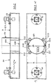
- the pipe section 70 consists in its outer structure of two end flanges 64A, 64B and two cylindrical, metallic outer tubes 61A, 61B, one end of which ends in the flanges 64A, 64B and the inner end of which is fixed in the opposite openings of the waveguide 50, so that the longitudinal plane of the waveguide 50 comes to lie perpendicular to the longitudinal axis of the pipe section 70.
- the flanges 64A, 64B overlap to form a continuous, inner ceramic tube 62.
- the inner surface of the ceramic tube 62 and the adjoining outer areas and end areas of the flanges 64A, 64B are lined with a tube 63 made of PTFE (Teflon), which seals the structure described against the flowing medium to be measured.
- PTFE Teflon
- the outer diameter of the metallic outer tubes 61A, 61B corresponds to the width of the waveguide 50, so that in the passage area of the ceramic tube 62 through the waveguide 50 there is an edge-side space or gap between the outer wall of the ceramic tube 62 and the opposite inner wall of the waveguide 50 remains.
- this intermediate space is filled with components which act as inductors, which are intended to compensate for the influence of the capacitance caused by the two openings in the waveguide, as is shown in more detail above.
- these components are realized here as metallic, shell-shaped diaphragm elements 66A, 66B, which are dimensioned such that they cause different phase shifts in the microwave passing through them, for example this can be achieved by a different cross-sectional design of the two elements 66A, 66B, as shown in FIG Figure 6 is shown.
- microwaves pass the pipeline 70 from the transmitter 61 to the receiver to a considerable extent. These microwaves thus represent an undesirable leakage radiation.
- the aperture elements 66A, 66B which are designed asymmetrically in the above-mentioned sense, it can at least approximately be achieved that the path difference between the two partial microwaves is approximately ⁇ / 2, so that when these are superimposed
- the two microwave components in the receiving section of the waveguide 50 (the left section in FIGS. 5 and 6) produce an extinction effect and this undesired leakage radiation can thus be at least largely eliminated. This significantly increases the usable dynamic range of the device, so that even a medium with very high damping can be measured with sufficient dynamics.
- FIG. 7 schematically shows this improved behavior of the device according to the invention:
- the two curves A and B shown show the actual damping D1 of a measured material and the damping D2 determined and displayed by the measuring device.
- the length L of the pipe section 70 was 172 mm
- the inner diameter D of the ceramic pipe 62 was 44 mm
- the length S of the waveguide 50 was 256 mm. Measurements were made in a microwave frequency range of 2.7 to 3.4 GHz, cream cheese and its dry matter content were measured as the medium to be measured certainly.
- the measured values determined here are shown in FIG. 8:% -TM means the dry matter content in% of the cream cheese and N the measuring points (21 measuring points in the example).
- the measuring points shown in triangles were determined with the inventive device described above, the measuring points shown in square form come from a laboratory analysis for control.
- the measuring points to be compared show a standard deviation of only + -0.37% -TM from the laboratory values.
- a rectangular waveguide was used; one of the flanges (64B) was equipped with an inner threaded ring 65 for holding the ceramic tube 62 in the flange 64B.
- the fundamental magnetic wave that passes through the medium is the H 1 1 wave.
Landscapes
- Physics & Mathematics (AREA)
- Biochemistry (AREA)
- Health & Medical Sciences (AREA)
- Life Sciences & Earth Sciences (AREA)
- Chemical & Material Sciences (AREA)
- Analytical Chemistry (AREA)
- Electromagnetism (AREA)
- General Health & Medical Sciences (AREA)
- General Physics & Mathematics (AREA)
- Immunology (AREA)
- Pathology (AREA)
- Length-Measuring Devices Using Wave Or Particle Radiation (AREA)
- Measurement Of Resistance Or Impedance (AREA)
- Investigating Or Analysing Materials By Optical Means (AREA)
Applications Claiming Priority (2)
| Application Number | Priority Date | Filing Date | Title |
|---|---|---|---|
| DE4211362A DE4211362C2 (de) | 1992-04-04 | 1992-04-04 | Vorrichtung zur Bestimmung von Materialparametern durch Mikrowellenmessungen |
| DE4211362 | 1992-04-04 |
Publications (2)
| Publication Number | Publication Date |
|---|---|
| EP0564879A1 true EP0564879A1 (fr) | 1993-10-13 |
| EP0564879B1 EP0564879B1 (fr) | 1997-12-17 |
Family
ID=6456093
Family Applications (1)
| Application Number | Title | Priority Date | Filing Date |
|---|---|---|---|
| EP93104608A Expired - Lifetime EP0564879B1 (fr) | 1992-04-04 | 1993-03-20 | Dispositif pour détermination des paramètres d'un matériau par mesures micro-ondes |
Country Status (4)
| Country | Link |
|---|---|
| US (1) | US5369368A (fr) |
| EP (1) | EP0564879B1 (fr) |
| AU (1) | AU662692B2 (fr) |
| DE (2) | DE4211362C2 (fr) |
Cited By (6)
| Publication number | Priority date | Publication date | Assignee | Title |
|---|---|---|---|---|
| RU2244293C2 (ru) * | 2002-09-30 | 2005-01-10 | Тамбовский военный авиационный инженерный институт | Свч - способ определения содержания влаги и степени ее засоленности в жидких средах |
| RU2287806C2 (ru) * | 2004-11-11 | 2006-11-20 | Тамбовский военный авиационный инженерный институт | Свч-способ определения объемного процентного содержания влагосодержащих присадок в жидких углеводородах и топливах |
| WO2012172333A1 (fr) * | 2011-06-13 | 2012-12-20 | The University Of Manchester | Appareil et procédé pour la mesure de fluide |
| EP2909623B1 (fr) * | 2012-10-22 | 2017-02-22 | M-Flow Technologies Ltd. | Cavité résonnante avec un tube pour l'échantillon et avec un élément remplissant la cavité, qui sont en matériau composite |
| EP3158325B1 (fr) | 2014-06-17 | 2020-04-01 | Hauni Maschinenbau GmbH | Dispositif de mesure à micro-ondes, ensemble et procédé de contrôle d'articles en forme de bâtonnet ou d'un boudin de matière issus de l'industrie de transformation du tabac, et machine de l'industrie de transformation du tabac |
| WO2024153291A1 (fr) | 2023-01-19 | 2024-07-25 | Technische Universität Hamburg, Körperschaft des öffentlichen Rechts | Procédé de mesure de la qualité d'un carburant et dispositif de mesure associé |
Families Citing this family (67)
| Publication number | Priority date | Publication date | Assignee | Title |
|---|---|---|---|---|
| US5345170A (en) | 1992-06-11 | 1994-09-06 | Cascade Microtech, Inc. | Wafer probe station having integrated guarding, Kelvin connection and shielding systems |
| US6380751B2 (en) | 1992-06-11 | 2002-04-30 | Cascade Microtech, Inc. | Wafer probe station having environment control enclosure |
| US5473256A (en) * | 1994-09-07 | 1995-12-05 | Texaco Inc. | Combination microwave waveguide and pressure barrier |
| US5483171A (en) * | 1994-09-07 | 1996-01-09 | Texaco Inc. | Determination of water cut and gas-fraction in oil/water/gas streams |
| US6232789B1 (en) | 1997-05-28 | 2001-05-15 | Cascade Microtech, Inc. | Probe holder for low current measurements |
| US5561377A (en) | 1995-04-14 | 1996-10-01 | Cascade Microtech, Inc. | System for evaluating probing networks |
| US5914613A (en) | 1996-08-08 | 1999-06-22 | Cascade Microtech, Inc. | Membrane probing system with local contact scrub |
| DE19651490C2 (de) * | 1996-12-11 | 2002-06-13 | Sig Combibloc Gmbh | Verfahren und Vorrichtung zur Ermittlung der Konzentration eines von Luft abweichenden Mediums in einem Aerosol |
| US6002263A (en) | 1997-06-06 | 1999-12-14 | Cascade Microtech, Inc. | Probe station having inner and outer shielding |
| DE19729730C1 (de) * | 1997-07-11 | 1999-04-22 | Goeller Arndt Dr | Vorrichtung zur Messung und/oder Abbildung elektrischer, magnetischer und mittelbar daraus ableitbarer Materialeigenschaften |
| US6292756B1 (en) | 1998-02-26 | 2001-09-18 | Premier Instruments, Inc. | Narrow band infrared water fraction apparatus for gas well and liquid hydrocarbon flow stream use |
| US6225812B1 (en) * | 1998-06-25 | 2001-05-01 | Rockwell Technologies, Llc | Method and apparatus for measuring the density of a substance having free water compensation |
| US6256882B1 (en) | 1998-07-14 | 2001-07-10 | Cascade Microtech, Inc. | Membrane probing system |
| DE19854550C5 (de) | 1998-11-26 | 2011-03-17 | Hauni Maschinenbau Ag | Resonatorgehäuse für Mikrowellen |
| US6578264B1 (en) | 1999-06-04 | 2003-06-17 | Cascade Microtech, Inc. | Method for constructing a membrane probe using a depression |
| US6445202B1 (en) | 1999-06-30 | 2002-09-03 | Cascade Microtech, Inc. | Probe station thermal chuck with shielding for capacitive current |
| US6211470B1 (en) | 1999-11-22 | 2001-04-03 | Westvaco Corporation | Height measurement apparatus for determining the volume/density of wood chips on a conveyor |
| US6838890B2 (en) | 2000-02-25 | 2005-01-04 | Cascade Microtech, Inc. | Membrane probing system |
| US6965226B2 (en) | 2000-09-05 | 2005-11-15 | Cascade Microtech, Inc. | Chuck for holding a device under test |
| US6914423B2 (en) | 2000-09-05 | 2005-07-05 | Cascade Microtech, Inc. | Probe station |
| DE10143173A1 (de) | 2000-12-04 | 2002-06-06 | Cascade Microtech Inc | Wafersonde |
| GB0117715D0 (en) * | 2001-07-19 | 2001-09-12 | Mrbp Res Ltd | Microwave biochemical analysis |
| US7355420B2 (en) | 2001-08-21 | 2008-04-08 | Cascade Microtech, Inc. | Membrane probing system |
| US6777964B2 (en) | 2002-01-25 | 2004-08-17 | Cascade Microtech, Inc. | Probe station |
| EP1509776A4 (fr) | 2002-05-23 | 2010-08-18 | Cascade Microtech Inc | Sonde d'essai d'un dispositif soumis essai |
| US6847219B1 (en) | 2002-11-08 | 2005-01-25 | Cascade Microtech, Inc. | Probe station with low noise characteristics |
| US6724205B1 (en) | 2002-11-13 | 2004-04-20 | Cascade Microtech, Inc. | Probe for combined signals |
| US7250779B2 (en) | 2002-11-25 | 2007-07-31 | Cascade Microtech, Inc. | Probe station with low inductance path |
| US6861856B2 (en) | 2002-12-13 | 2005-03-01 | Cascade Microtech, Inc. | Guarded tub enclosure |
| DE10306217B4 (de) * | 2003-02-13 | 2014-06-26 | Rieter Ingolstadt Gmbh | Mikrowellenresonator, Textilmaschine mit einem derartigen Resonator sowie Raumeinheit für einen derartigen Resonator |
| US7221172B2 (en) | 2003-05-06 | 2007-05-22 | Cascade Microtech, Inc. | Switched suspended conductor and connection |
| US7057404B2 (en) | 2003-05-23 | 2006-06-06 | Sharp Laboratories Of America, Inc. | Shielded probe for testing a device under test |
| US7492172B2 (en) | 2003-05-23 | 2009-02-17 | Cascade Microtech, Inc. | Chuck for holding a device under test |
| DE10334144A1 (de) * | 2003-07-01 | 2005-01-20 | Rieter Ingolstadt Spinnereimaschinenbau Ag | Microwellenresonator, Textilmaschinen mit einem derartigen Resonator sowie Raumeinheit für einen derartigen Resonator |
| US7250626B2 (en) | 2003-10-22 | 2007-07-31 | Cascade Microtech, Inc. | Probe testing structure |
| US7187188B2 (en) | 2003-12-24 | 2007-03-06 | Cascade Microtech, Inc. | Chuck with integrated wafer support |
| DE202004021093U1 (de) | 2003-12-24 | 2006-09-28 | Cascade Microtech, Inc., Beaverton | Aktiver Halbleiterscheibenmessfühler |
| DE102004004329B4 (de) * | 2004-01-24 | 2010-04-22 | Eastman Kodak Co. | Einrichtung und Verfahren zum Einstellen einer Fixiereinrichtung und Fixiereinrichtung einer digitalen Druckmaschine |
| WO2005121824A2 (fr) | 2004-06-07 | 2005-12-22 | Cascade Microtech, Inc. | Support individuel optique thermique |
| US7330041B2 (en) | 2004-06-14 | 2008-02-12 | Cascade Microtech, Inc. | Localizing a temperature of a device for testing |
| JP4980903B2 (ja) | 2004-07-07 | 2012-07-18 | カスケード マイクロテック インコーポレイテッド | 膜懸垂プローブを具えるプローブヘッド |
| US7420381B2 (en) | 2004-09-13 | 2008-09-02 | Cascade Microtech, Inc. | Double sided probing structures |
| US7535247B2 (en) | 2005-01-31 | 2009-05-19 | Cascade Microtech, Inc. | Interface for testing semiconductors |
| US7656172B2 (en) | 2005-01-31 | 2010-02-02 | Cascade Microtech, Inc. | System for testing semiconductors |
| US7449899B2 (en) | 2005-06-08 | 2008-11-11 | Cascade Microtech, Inc. | Probe for high frequency signals |
| JP5080459B2 (ja) | 2005-06-13 | 2012-11-21 | カスケード マイクロテック インコーポレイテッド | 広帯域能動/受動差動信号プローブ |
| RU2301418C1 (ru) * | 2006-01-17 | 2007-06-20 | Тамбовское высшее военное авиационное инженерное училище радиоэлектроники (военный институт) | Свч-способ определения растворенной и осажденной влаги в жидких углеводородах |
| RU2306552C1 (ru) * | 2006-02-03 | 2007-09-20 | Тамбовское высшее военное авиационное инженерное училище радиоэлектроники (военный институт) | Свч-способ определения наличия взвешенной влаги в жидких углеводородах |
| DE202007018733U1 (de) | 2006-06-09 | 2009-03-26 | Cascade Microtech, Inc., Beaverton | Messfühler für differentielle Signale mit integrierter Symmetrieschaltung |
| US7443186B2 (en) | 2006-06-12 | 2008-10-28 | Cascade Microtech, Inc. | On-wafer test structures for differential signals |
| US7764072B2 (en) | 2006-06-12 | 2010-07-27 | Cascade Microtech, Inc. | Differential signal probing system |
| US7403028B2 (en) | 2006-06-12 | 2008-07-22 | Cascade Microtech, Inc. | Test structure and probe for differential signals |
| US7723999B2 (en) | 2006-06-12 | 2010-05-25 | Cascade Microtech, Inc. | Calibration structures for differential signal probing |
| US20080012578A1 (en) * | 2006-07-14 | 2008-01-17 | Cascade Microtech, Inc. | System for detecting molecular structure and events |
| US7876114B2 (en) | 2007-08-08 | 2011-01-25 | Cascade Microtech, Inc. | Differential waveguide probe |
| US7888957B2 (en) | 2008-10-06 | 2011-02-15 | Cascade Microtech, Inc. | Probing apparatus with impedance optimized interface |
| US8410806B2 (en) | 2008-11-21 | 2013-04-02 | Cascade Microtech, Inc. | Replaceable coupon for a probing apparatus |
| US8319503B2 (en) | 2008-11-24 | 2012-11-27 | Cascade Microtech, Inc. | Test apparatus for measuring a characteristic of a device under test |
| US9038451B2 (en) * | 2010-07-08 | 2015-05-26 | Baker Hughes Incorporated | Optical method for determining fouling of crude and heavy fuels |
| CN102305800B (zh) * | 2011-07-29 | 2013-05-08 | 华南理工大学 | 基于超宽带的易燃液体检测方法 |
| JP6376214B2 (ja) * | 2014-03-26 | 2018-08-22 | 王子ホールディングス株式会社 | 液体中の水分測定装置および水分測定方法 |
| NO20140689A1 (no) * | 2014-06-03 | 2015-12-04 | Roxar Flow Measurement As | Cutoff regulator |
| CA2957156C (fr) | 2014-08-19 | 2021-10-19 | Emirates Innovations | Procede et appareil de detection de contaminants dans des ecoulements de fluides sous pression |
| RU2579359C1 (ru) * | 2015-02-05 | 2016-04-10 | Федеральное государственное бюджетное учреждение науки Институт проблем управления им. В.А. Трапезникова РАН | Способ измерения физической величины |
| JP6551052B2 (ja) * | 2015-08-25 | 2019-07-31 | 王子ホールディングス株式会社 | 粉体中の水分率測定装置および方法 |
| EP3339844A1 (fr) | 2016-12-21 | 2018-06-27 | DSE Test Solutions A/S | Dispositif de détermination des paramètres de substance au moyen d'ondes électromagnétiques |
| DE102018208428B3 (de) | 2018-05-29 | 2019-07-04 | Conti Temic Microelectronic Gmbh | Vorrichtung und Verfahren zur Prüfung von Materialeigenschaften eines Platinensubstrats |
Citations (3)
| Publication number | Priority date | Publication date | Assignee | Title |
|---|---|---|---|---|
| EP0011185A1 (fr) * | 1978-11-11 | 1980-05-28 | Bayer Ag | Dispositif de mesure du taux d'humidité par micro-ondes avec échelles de mesure commutables |
| DE3412704A1 (de) * | 1983-04-06 | 1984-10-11 | Nippondenso Co., Ltd., Kariya, Aichi | Vorrichtung zum messen des alkoholgehaltes in kraftstoffgemischen |
| EP0372843A1 (fr) * | 1988-12-05 | 1990-06-13 | Texaco Development Corporation | Dispositif d'indication du contenu de l'eau d'un courant de pétrole |
Family Cites Families (7)
| Publication number | Priority date | Publication date | Assignee | Title |
|---|---|---|---|---|
| US3551806A (en) * | 1967-04-03 | 1970-12-29 | Shinichi Sasaki | Microwave apparatus for determining moisture content of hygroscopic webs,especially during manufacture |
| US4301400A (en) * | 1979-12-26 | 1981-11-17 | Texaco Inc. | Microwave water in crude monitor |
| DE3316328A1 (de) * | 1982-05-27 | 1983-12-01 | Atomic Energy of Canada Ltd., Ottawa, Ontario | Mikrowellen-messgeraet fuer den leerraumanteil in einer fluessigkeitsstroemung |
| JPS63145951A (ja) * | 1986-12-09 | 1988-06-18 | Daipoole:Kk | 糸状材料の物性量測定装置 |
| FR2619217B1 (fr) * | 1987-08-04 | 1989-11-10 | Aerospatiale | Dispositif de mesure en continu du taux d'impregnation par une substance de fibres conductrices ou non d'electricite. |
| JPH03229141A (ja) * | 1990-02-05 | 1991-10-11 | Daipoole:Kk | 糸状材料内の混入導電物質検知装置 |
| US5144224A (en) * | 1991-04-01 | 1992-09-01 | Larsen Lawrence E | Millimeter wave flow cytometer |
-
1992
- 1992-04-04 DE DE4211362A patent/DE4211362C2/de not_active Expired - Fee Related
-
1993
- 1993-03-20 DE DE59307837T patent/DE59307837D1/de not_active Expired - Fee Related
- 1993-03-20 EP EP93104608A patent/EP0564879B1/fr not_active Expired - Lifetime
- 1993-04-02 US US08/042,420 patent/US5369368A/en not_active Expired - Lifetime
- 1993-04-05 AU AU36705/93A patent/AU662692B2/en not_active Ceased
Patent Citations (3)
| Publication number | Priority date | Publication date | Assignee | Title |
|---|---|---|---|---|
| EP0011185A1 (fr) * | 1978-11-11 | 1980-05-28 | Bayer Ag | Dispositif de mesure du taux d'humidité par micro-ondes avec échelles de mesure commutables |
| DE3412704A1 (de) * | 1983-04-06 | 1984-10-11 | Nippondenso Co., Ltd., Kariya, Aichi | Vorrichtung zum messen des alkoholgehaltes in kraftstoffgemischen |
| EP0372843A1 (fr) * | 1988-12-05 | 1990-06-13 | Texaco Development Corporation | Dispositif d'indication du contenu de l'eau d'un courant de pétrole |
Cited By (8)
| Publication number | Priority date | Publication date | Assignee | Title |
|---|---|---|---|---|
| RU2244293C2 (ru) * | 2002-09-30 | 2005-01-10 | Тамбовский военный авиационный инженерный институт | Свч - способ определения содержания влаги и степени ее засоленности в жидких средах |
| RU2287806C2 (ru) * | 2004-11-11 | 2006-11-20 | Тамбовский военный авиационный инженерный институт | Свч-способ определения объемного процентного содержания влагосодержащих присадок в жидких углеводородах и топливах |
| WO2012172333A1 (fr) * | 2011-06-13 | 2012-12-20 | The University Of Manchester | Appareil et procédé pour la mesure de fluide |
| EP2909623B1 (fr) * | 2012-10-22 | 2017-02-22 | M-Flow Technologies Ltd. | Cavité résonnante avec un tube pour l'échantillon et avec un élément remplissant la cavité, qui sont en matériau composite |
| US10386281B2 (en) | 2012-10-22 | 2019-08-20 | M-Flow Technologies Ltd | Fluid sensor |
| EP3158325B1 (fr) | 2014-06-17 | 2020-04-01 | Hauni Maschinenbau GmbH | Dispositif de mesure à micro-ondes, ensemble et procédé de contrôle d'articles en forme de bâtonnet ou d'un boudin de matière issus de l'industrie de transformation du tabac, et machine de l'industrie de transformation du tabac |
| WO2024153291A1 (fr) | 2023-01-19 | 2024-07-25 | Technische Universität Hamburg, Körperschaft des öffentlichen Rechts | Procédé de mesure de la qualité d'un carburant et dispositif de mesure associé |
| DE102023101256A1 (de) * | 2023-01-19 | 2024-07-25 | Technische Universität Hamburg, Körperschaft des öffentlichen Rechts | Verfahren zur Messung der Qualität eines Kraftstoffes und Messvorrichtung dafür |
Also Published As
| Publication number | Publication date |
|---|---|
| US5369368A (en) | 1994-11-29 |
| DE59307837D1 (de) | 1998-01-29 |
| AU662692B2 (en) | 1995-09-07 |
| EP0564879B1 (fr) | 1997-12-17 |
| DE4211362C2 (de) | 1995-04-20 |
| DE4211362A1 (de) | 1993-10-14 |
| AU3670593A (en) | 1993-10-14 |
Similar Documents
| Publication | Publication Date | Title |
|---|---|---|
| EP0564879B1 (fr) | Dispositif pour détermination des paramètres d'un matériau par mesures micro-ondes | |
| EP0468023B1 (fr) | Procede d'evaluation de l'humidite d'un produit a l'aide de micro-ondes et dispositif d'execution du procede | |
| EP0889321B1 (fr) | Capteur d'humidité et de densité | |
| DE10112499B4 (de) | Resonatoreinrichtung, insbesondere Mikrowellenresonatoreinrichtung | |
| DE4342505C1 (de) | Verfahren und Vorrichtung zur Messung der Dielektrizitätskonstante von Probenmaterialien | |
| DE69712759T2 (de) | Wirbelstromprüftechnik | |
| DE69732194T2 (de) | Gasanalysator und Verfahren zu dessen Kalibrierung | |
| DE69022421T2 (de) | Mikrowellenvorrichtung und verfahren zum messen von flüssigkeitsmischungen. | |
| AT517604B1 (de) | Messfühler | |
| EP3158325B1 (fr) | Dispositif de mesure à micro-ondes, ensemble et procédé de contrôle d'articles en forme de bâtonnet ou d'un boudin de matière issus de l'industrie de transformation du tabac, et machine de l'industrie de transformation du tabac | |
| DE2928487A1 (de) | Verfahren zur messung der relativen feuchte eines messgutes mit hilfe von mikrowellen im ghz-bereich | |
| DE19908583A1 (de) | Vorrichtung zur kontinuierlichen Ermittlung der UV-Transmission fließender oder strömender Medien | |
| EP0272645A2 (fr) | Procédé de mesure sélective de matériaux de charge dans des bandes de matériaux en défilement, en particulier bandes de papier | |
| CH670514A5 (fr) | ||
| DE3317215A1 (de) | Verfahren zur quantitativen bestimmung von probenpartikeln | |
| DE2717301B1 (de) | Messumformer zur kapazitiven Fuellstandsmessung von Fluessigkeitsfuellungen | |
| DE102007056682A1 (de) | Vorrichtung und Messanordnung zur Ermittlung der Partikelkonzentration, der Partikelgröße, der mittleren Partikelgröße und der Partikelgrößenverteilung der Partikeln einer dispersen Phase innerhalb eines dispersen Systems sowie dessen Trübung | |
| DE2819731A1 (de) | Anordnung zur kapazitiven fuellstandsmessung in einem behaelter | |
| EP1331476A1 (fr) | Appareil à micro-ondes pour des mesures de l'humidité, avec compensation de température | |
| DE3518186A1 (de) | Vorrichtung zur erfassung der effektiven dielektrizitaetskonstanten eines mediums, insbesondere zur bestimmung des wasseranteils in einem gefuellten behaelter fuer oel oder alkohol | |
| DE3750237T2 (de) | Vorrichtung zur Feststellung von Oberflächenmikrofehlern in einem Metallwerkstück. | |
| DE102006034884A1 (de) | Messgerät zur Bestimmung der elektromagnetischen Eigenschaften eines Fluids | |
| EP4548087A1 (fr) | Procédé et dispositif de test de flux parasite de matériau de test ferromagnétique avec normalisation de signal | |
| DE2038542C3 (de) | Vorrichtung zur Messung des Schwebstoffgehaltes eines Strömungsmittels | |
| DE2902471C2 (de) | Anordnung zur Bestimmung eines Flüssigkeitspegels |
Legal Events
| Date | Code | Title | Description |
|---|---|---|---|
| PUAI | Public reference made under article 153(3) epc to a published international application that has entered the european phase |
Free format text: ORIGINAL CODE: 0009012 |
|
| AK | Designated contracting states |
Kind code of ref document: A1 Designated state(s): DE FR GB NL |
|
| 17P | Request for examination filed |
Effective date: 19940323 |
|
| 17Q | First examination report despatched |
Effective date: 19960404 |
|
| GRAG | Despatch of communication of intention to grant |
Free format text: ORIGINAL CODE: EPIDOS AGRA |
|
| GRAG | Despatch of communication of intention to grant |
Free format text: ORIGINAL CODE: EPIDOS AGRA |
|
| GRAH | Despatch of communication of intention to grant a patent |
Free format text: ORIGINAL CODE: EPIDOS IGRA |
|
| GRAH | Despatch of communication of intention to grant a patent |
Free format text: ORIGINAL CODE: EPIDOS IGRA |
|
| GRAA | (expected) grant |
Free format text: ORIGINAL CODE: 0009210 |
|
| AK | Designated contracting states |
Kind code of ref document: B1 Designated state(s): DE FR GB NL |
|
| REF | Corresponds to: |
Ref document number: 59307837 Country of ref document: DE Date of ref document: 19980129 |
|
| ET | Fr: translation filed | ||
| GBT | Gb: translation of ep patent filed (gb section 77(6)(a)/1977) |
Effective date: 19980317 |
|
| PLBE | No opposition filed within time limit |
Free format text: ORIGINAL CODE: 0009261 |
|
| 26N | No opposition filed | ||
| REG | Reference to a national code |
Ref country code: GB Ref legal event code: IF02 |
|
| NLS | Nl: assignments of ep-patents |
Owner name: BERTHOLD TECHNOLOGIES GMBH & CO. KG |
|
| NLT1 | Nl: modifications of names registered in virtue of documents presented to the patent office pursuant to art. 16 a, paragraph 1 |
Owner name: PERKINELMER OPTOELECTRONICS GMBH & CO. KG Owner name: PERKINELMER GMBH & CO. KG Owner name: BERTHOLD GMBH & CO. KG |
|
| REG | Reference to a national code |
Ref country code: FR Ref legal event code: TP |
|
| PGFP | Annual fee paid to national office [announced via postgrant information from national office to epo] |
Ref country code: NL Payment date: 20090324 Year of fee payment: 17 |
|
| PGFP | Annual fee paid to national office [announced via postgrant information from national office to epo] |
Ref country code: GB Payment date: 20090324 Year of fee payment: 17 |
|
| PGFP | Annual fee paid to national office [announced via postgrant information from national office to epo] |
Ref country code: DE Payment date: 20081127 Year of fee payment: 17 |
|
| PGFP | Annual fee paid to national office [announced via postgrant information from national office to epo] |
Ref country code: FR Payment date: 20090318 Year of fee payment: 17 |
|
| REG | Reference to a national code |
Ref country code: NL Ref legal event code: V1 Effective date: 20101001 |
|
| GBPC | Gb: european patent ceased through non-payment of renewal fee |
Effective date: 20100320 |
|
| REG | Reference to a national code |
Ref country code: FR Ref legal event code: ST Effective date: 20101130 |
|
| PG25 | Lapsed in a contracting state [announced via postgrant information from national office to epo] |
Ref country code: NL Free format text: LAPSE BECAUSE OF NON-PAYMENT OF DUE FEES Effective date: 20101001 Ref country code: FR Free format text: LAPSE BECAUSE OF NON-PAYMENT OF DUE FEES Effective date: 20100331 |
|
| PG25 | Lapsed in a contracting state [announced via postgrant information from national office to epo] |
Ref country code: DE Free format text: LAPSE BECAUSE OF NON-PAYMENT OF DUE FEES Effective date: 20101001 |
|
| PG25 | Lapsed in a contracting state [announced via postgrant information from national office to epo] |
Ref country code: GB Free format text: LAPSE BECAUSE OF NON-PAYMENT OF DUE FEES Effective date: 20100320 |