EP0565009A1 - Appareil d'installation - Google Patents
Appareil d'installation Download PDFInfo
- Publication number
- EP0565009A1 EP0565009A1 EP93105553A EP93105553A EP0565009A1 EP 0565009 A1 EP0565009 A1 EP 0565009A1 EP 93105553 A EP93105553 A EP 93105553A EP 93105553 A EP93105553 A EP 93105553A EP 0565009 A1 EP0565009 A1 EP 0565009A1
- Authority
- EP
- European Patent Office
- Prior art keywords
- contact
- lever
- holder
- shaft
- contact lever
- Prior art date
- Legal status (The legal status is an assumption and is not a legal conclusion. Google has not performed a legal analysis and makes no representation as to the accuracy of the status listed.)
- Withdrawn
Links
Images


Classifications
-
- H—ELECTRICITY
- H01—ELECTRIC ELEMENTS
- H01H—ELECTRIC SWITCHES; RELAYS; SELECTORS; EMERGENCY PROTECTIVE DEVICES
- H01H1/00—Contacts
- H01H1/50—Means for increasing contact pressure, preventing vibration of contacts, holding contacts together after engagement, or biasing contacts to the open position
-
- H—ELECTRICITY
- H01—ELECTRIC ELEMENTS
- H01H—ELECTRIC SWITCHES; RELAYS; SELECTORS; EMERGENCY PROTECTIVE DEVICES
- H01H1/00—Contacts
- H01H1/12—Contacts characterised by the manner in which co-operating contacts engage
- H01H1/14—Contacts characterised by the manner in which co-operating contacts engage by abutting
- H01H1/22—Contacts characterised by the manner in which co-operating contacts engage by abutting with rigid pivoted member carrying the moving contact
- H01H1/221—Contacts characterised by the manner in which co-operating contacts engage by abutting with rigid pivoted member carrying the moving contact and a contact pressure spring acting between the pivoted member and a supporting member
- H01H1/225—Contacts characterised by the manner in which co-operating contacts engage by abutting with rigid pivoted member carrying the moving contact and a contact pressure spring acting between the pivoted member and a supporting member the supporting member being pivotable
Definitions
- the invention relates to a contact arrangement for an installation switch, preferably for a residual current or residual current circuit breaker, according to the preamble of claim 1.
- the movable contact pieces are attached to contact levers which are themselves rotatably mounted in a control shaft.
- the selector shaft has openings corresponding to the number of contact levers, transverse to the central axis of the selector shaft, and each contact lever has pins on both sides, which are inserted into recesses in the openings.
- each contact lever is provided with an L-shaped fold at its end opposite the contact piece, which engages behind a web bridging the associated opening parallel to the axis of rotation of the selector shaft.
- a tension spring is used as the contact pressure and return spring provided, one end of which is hooked onto the contact lever and the other end of which is attached to the housing of the installation device, the point of application of the tension spring on the contact lever being between the central axis of the control shaft or the bevel and the axis of rotation of the contact lever in the control shaft. Since the spring must reach through the selector shaft, the selector shaft has one passage each, which - depending on the position of the spring in the selector shaft - runs transversely to the axis of rotation of the selector shaft and at a distance from it.
- the control shaft is mounted in the housing of the installation switch itself.
- the tension spring is difficult to assemble and the position of the spring in the housing is unsafe when actuated.
- special wall parts must be provided for the purpose of fastening or hanging the tension spring. Since the housing and the selector shaft are made of thermoset plastic, the friction between the selector shaft and the housing is high, which means that lubrication is required.
- the object of the invention is to provide a contact arrangement of the type mentioned, in which the assembly is simplified and lubrication is no longer required.
- the contact lever is accommodated in a control shaft, which in turn is guided in a holder that can be fixed in the housing of the installation switch.
- the compression spring which is required to generate the contact pressure or a reset process, is fixed between the contact lever and the holder, whereby all three components are one Form a unit that can be preassembled and used as a unit in an electrical installation device.
- the holder preferably has a plate-shaped base, on each of which a mouth-forming projections are provided, each of which partially delimit a circular space.
- the jaw opening is smaller than the diameter of the roller part of the selector shaft, the roller part provided on the selector shaft can be snapped, so that the holder forms a unit with the selector shaft.
- a limiting groove or a limiting lug or limiting tooth are provided in accordance with the characterizing features of claim 4.
- each opening of the control shaft for the movable contact lever is provided with a stop which is diametrically related to the central axis of rotation of the control shaft to the axis of rotation of the contact lever according to the characterizing features of claim 5 is arranged opposite, such that after opening the contact points, the springs press the associated contact lever against the stop and thus firmly couple the contact lever with the control shaft.
- a nub for each spring is preferably arranged according to claim 6 on the plate-shaped base of the holder, over which the spring is inserted and on which the spring can be fixed by friction.
- the holder for the selector shaft is an independent part and can be easily inserted into the housing of the installation switch, the holder and the selector shaft can each be made of a thermoplastic, so that the friction between the two is kept low and the rotary movement against one another is free of wear can be done.
- FIG. 1 shows the lower part 10 of a housing of a residual current circuit breaker, which is cup-shaped and has a receiving space 11 in the center, for example for the converter of the residual current circuit breaker.
- the receiving space 11 is closed to the narrow sides 12 and 13 by means of partitions 14 and 15 from a terminal space and a contact point receiving space 17.
- a hat carrier-like contact carrier rail 18 which is aligned perpendicular to the bottom wall 19 of the lower part and is inserted with a leg end 20 into a pocket 21 for holding.
- the other leg end 22 is connected to a terminal 23 in a terminal space 24.
- the contact carrier rail 18 has a fixed contact piece 25 in the center, which cooperates with a movable contact piece 27 fastened to a contact lever 26.
- the contact lever 26 is received in a contact carrier 28 designed as a switching shaft, which is rotatably mounted in a holder 29, as will be shown in more detail below.
- Figure 1 shows the switching device in the on position.
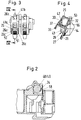
- FIGS. 5 to 7. show the holder 29 in three views.
- the holder 29 has a base plate 30 which has on its one side surface approximately in the middle two arms 32 and 33 which delimit a mouth opening 31 and which delimit a partial arc, the mouth opening 31 which the two arms 32 and 33 take between them being smaller than the diameter R of the mouth opening 31.
- a nose 34 is formed which projects into the mouth opening 31.
- two projections 35 and 36 are formed on both sides of the arm 32 and at a distance therefrom perpendicular to the base plate 30, which extend approximately to the center of the distance from the center of the mouth opening 31 from the base plate project.
- the base plate 30 Approximately in the area of the arm 33, the base plate 30 has two pins 37 and 38 on both sides of the arm 33, which are located exactly below the extensions 35 and 36, respectively.
- the diameter of the pin 37 and 38 is dimensioned such that a helical compression spring 39 and 40 can be placed over the pin 37 or 38 and is held on the pin 37 and 38 by friction.
- the holder 29 with the pin 37 and the helical compression spring 39 can be seen in particular in FIG. 4.
- the arm 32 can be seen in part.
- the switching shaft 28 serving as a contact lever carrier is connected to the holder 29.
- the switching shaft 28 has spaces 41 corresponding to the number of contact pieces (FIG. 8 only shows one space), which are bridged by means of webs 42 and 43.
- the spaces 41 are delimited on both sides by means of plate elements 44 and 45, further spaces 46 and 47 being provided between the plate parts 45 and 44 outside the plate parts 44 and 45, which spaces are bridged by means of a shift drum section 48 and 49, the center lines SM of which are perpendicular to the alignment of the plate parts 44 and 45 and run parallel to the webs 42 and 43.
- the webs 42 and 43 are of course connected to the side surfaces of the spaces 41.
- the diameter of the shift drum sections 48 and 49 corresponds to the diameter of the jaw opening 31, so that the arms 32 and 33 can be pushed over the shift drum sections 48 and 49, so that the shift shaft 28 is locked with the holder 29.
- the holder according to Figures 5 to 7 is a holder for a two-pole version of a residual current circuit breaker; the associated switching shaft 28 has two interstices 41 and only one switching drum section 48. If a multipole version of a residual current circuit breaker is to be fitted, then a number of interstices corresponding to the number of contact points is provided; this also results in a corresponding number of arms 32/33.
- each space has two sections 41a and 41b; the space 41a has a larger width than the space 41b, which is due to the design of the contact lever 26.
- the contact lever 26 also has sections of different widths, namely a section 26a with a larger width and a section 26b with a smaller width.
- the lugs 26c are located at a short distance from the contact-side end of the contact lever 26 and the opposite end has a nose or L-shaped bend 53 which protrudes from the switching shaft as well as the contact-side end of the contact lever.
- the contact lever On the side of the contact lever on which the movable contact piece 27 is fastened, the contact lever also has a nose 54, the diameter of which corresponds to the inside diameter of the helical compression spring 39, so that the nose 54 can reach into the interior of the helical compression spring 39.
- the helical compression spring 39 presses the contact lever into the open position, i.e. away from the base plate 30, so that the contact lever 26 comes to rest against the web 55, as a result of which a rigid between the control shaft 28 and the contact lever 26 Connection is achieved.
- the webs 43, 42 and 55 are arranged virtually at the corners of a triangle, the webs 43 and 42 bridging the gap 41 on the side of the contact lever 26 facing the movable contact piece 27, whereas the web 55 is arranged on the opposite side of the contact lever .
- the web 55 has on its surface facing the contact lever a guide tip 56 which engages in a concave recess 57 on the contact lever when the contact lever is in the switch-off position shown in FIG. 4; the tip 56 together with the recess 57 serves as a defined support cutting edge for the contact lever.
- the shift drum sections 48, 49 have a groove 58 covering a partial section of the circumference, into which the nose 34 engages in the assembled state and thus limits the rotational movement of the shift shaft 28 in the holder 30.
- the springs 39, 40 are placed on their associated pins 37 and 38 on the base plate 30 of the holder; so then the contact lever 26 are inserted into the spaces 41 such that the contact levers are between the webs 43 and 42 and 55, then the control shaft 28 is connected to the holder together with the contact carriers therein such that the arms 32 and 33 snap over the shift drum sections 48 and 49 and grip the other, previously free end of the helical compression springs 39 and 40 via the corresponding pins 54 on the contact levers 26. It must still be added that the two lugs 26c are inserted into the recesses 50 and 51.
- the holder 30 and the control shaft 28 are made of thermoplastic, so that an optimal friction is generated between the two.
Landscapes
- Rotary Switch, Piano Key Switch, And Lever Switch (AREA)
- Breakers (AREA)
Applications Claiming Priority (2)
| Application Number | Priority Date | Filing Date | Title |
|---|---|---|---|
| DE19924211916 DE4211916A1 (de) | 1992-04-09 | 1992-04-09 | Installationsgerät |
| DE4211916 | 1992-04-09 |
Publications (1)
| Publication Number | Publication Date |
|---|---|
| EP0565009A1 true EP0565009A1 (fr) | 1993-10-13 |
Family
ID=6456452
Family Applications (1)
| Application Number | Title | Priority Date | Filing Date |
|---|---|---|---|
| EP93105553A Withdrawn EP0565009A1 (fr) | 1992-04-09 | 1993-04-03 | Appareil d'installation |
Country Status (3)
| Country | Link |
|---|---|
| EP (1) | EP0565009A1 (fr) |
| CN (1) | CN1079334A (fr) |
| DE (1) | DE4211916A1 (fr) |
Cited By (2)
| Publication number | Priority date | Publication date | Assignee | Title |
|---|---|---|---|---|
| EP0869526A3 (fr) * | 1997-04-03 | 1999-03-31 | Eaton Corporation | Sous-ensemble avec ressorts de contact pour disjoncteur, procédé et appareil pour la fabrication, et disjoncteur comportant ce sous-ensemble |
| CN104319190A (zh) * | 2014-10-15 | 2015-01-28 | 河南平高电气股份有限公司 | 断路器静触头座装夹工装 |
Citations (4)
| Publication number | Priority date | Publication date | Assignee | Title |
|---|---|---|---|---|
| US3004125A (en) * | 1959-06-18 | 1961-10-10 | Licentia Gmbh | Switch |
| DE1909358U (de) * | 1964-11-11 | 1965-02-04 | Stotz Kontakt Gmbh | Schalter mit einer haltevorrichtung am kontakttraeger fuer einen mit einer kontaktdruckfeder zusammenarbeitenden kontaktfinger. |
| FR2105077A2 (fr) * | 1970-09-23 | 1972-04-28 | Legrand Sa | |
| FR2484136A1 (fr) * | 1980-06-06 | 1981-12-11 | Merlin Gerin | Contacts electriques perfectionnes pour disjoncteurs multipolaires a basse tension et procede de fabrication des contacts |
Family Cites Families (9)
| Publication number | Priority date | Publication date | Assignee | Title |
|---|---|---|---|---|
| US3867598A (en) * | 1973-10-09 | 1975-02-18 | Westinghouse Electric Corp | Control switch |
| AT339991B (de) * | 1974-02-08 | 1977-11-25 | Schrack Elektrizitaets Ag E | Fehlerstrom- bzw. fehlerspannungsschutzschalter od.dgl. |
| DD142621A1 (de) * | 1979-03-23 | 1980-07-02 | Dietrich Amft | Brueckenkontaktanordnung fuer handschalter mit asymmetrischer schaltstueckoeffnung |
| JPS6070626A (ja) * | 1983-09-26 | 1985-04-22 | 富士電機株式会社 | 回路しゃ断器の接触子機構 |
| DE3606508A1 (de) * | 1986-02-28 | 1987-09-03 | Jung Albrecht Fa | Schaltmechanismus fuer ein elektrisches installationsgeraet |
| DE3732468A1 (de) * | 1987-09-23 | 1989-04-06 | Siemens Ag | Kontaktanordnung eines niederspannungs-leistungsschalters mit elektrodynamischer oeffnung |
| FR2626105B1 (fr) * | 1988-01-20 | 1990-06-15 | Hager Electro | Appareil de protection d'installations electriques |
| DE8802393U1 (de) * | 1988-02-24 | 1988-05-11 | Lindner GmbH Fabrik elektrischer Lampen und Apparate, 96052 Bamberg | Aus Haupt- und Hilfsschalter bestehende Schalterkombination |
| JPH02136940U (fr) * | 1989-04-19 | 1990-11-15 |
-
1992
- 1992-04-09 DE DE19924211916 patent/DE4211916A1/de not_active Withdrawn
-
1993
- 1993-04-03 EP EP93105553A patent/EP0565009A1/fr not_active Withdrawn
- 1993-04-08 CN CN 93104443 patent/CN1079334A/zh active Pending
Patent Citations (4)
| Publication number | Priority date | Publication date | Assignee | Title |
|---|---|---|---|---|
| US3004125A (en) * | 1959-06-18 | 1961-10-10 | Licentia Gmbh | Switch |
| DE1909358U (de) * | 1964-11-11 | 1965-02-04 | Stotz Kontakt Gmbh | Schalter mit einer haltevorrichtung am kontakttraeger fuer einen mit einer kontaktdruckfeder zusammenarbeitenden kontaktfinger. |
| FR2105077A2 (fr) * | 1970-09-23 | 1972-04-28 | Legrand Sa | |
| FR2484136A1 (fr) * | 1980-06-06 | 1981-12-11 | Merlin Gerin | Contacts electriques perfectionnes pour disjoncteurs multipolaires a basse tension et procede de fabrication des contacts |
Cited By (2)
| Publication number | Priority date | Publication date | Assignee | Title |
|---|---|---|---|---|
| EP0869526A3 (fr) * | 1997-04-03 | 1999-03-31 | Eaton Corporation | Sous-ensemble avec ressorts de contact pour disjoncteur, procédé et appareil pour la fabrication, et disjoncteur comportant ce sous-ensemble |
| CN104319190A (zh) * | 2014-10-15 | 2015-01-28 | 河南平高电气股份有限公司 | 断路器静触头座装夹工装 |
Also Published As
| Publication number | Publication date |
|---|---|
| DE4211916A1 (de) | 1993-10-14 |
| CN1079334A (zh) | 1993-12-08 |
Similar Documents
| Publication | Publication Date | Title |
|---|---|---|
| DE19726149C2 (de) | Schalteranordnung | |
| DE1920784A1 (de) | Schiebeschalter fuer Geraete mit einem von einer Isolierstoffplatte getragenen Leiternetz | |
| DE4316998A1 (de) | Elektrischer Drucktastenschalter | |
| DE3829109A1 (de) | Elektrischer schalter, insbesondere lenstockschalter fuer kratfahrzeuge | |
| DE10027484C1 (de) | Kipp-Schiebe-Schalter | |
| DE3942925C2 (fr) | ||
| DE2835256C2 (de) | Schiebeschalter, insbesondere zur Anordnung im Schalthebelende eines Lenkstockschalters | |
| DE2705756C2 (de) | Druckknopfschalter für elektronische Tischrechner o.dgl. | |
| DE2804146A1 (de) | Stoesselschalter- und potentiometerkombination | |
| DE2904899C2 (de) | Elektrischer Schalter | |
| DE2524287A1 (de) | Elektrischer schalter | |
| DE4319615C2 (de) | Elektrischer Schalter zum Schalten eines Elektromotors, insbesondere in einer elektrischen Zahnbürste | |
| DE2559861B1 (de) | Verriegelbarer Drucktastenschalter | |
| EP0565009A1 (fr) | Appareil d'installation | |
| EP0068483B1 (fr) | Commutateur électromécanique pour appareils téléphoniques | |
| DE3739296A1 (de) | Impulsgenerator | |
| DE2827854C2 (de) | Elektrischer Wippenschalter | |
| DE19858118C1 (de) | Schalteranordnung | |
| DE2511510C2 (de) | Elektrischer Installationsschalter | |
| DE3940285C2 (fr) | ||
| EP0502394B1 (fr) | Configuration des contacts | |
| EP0565008B1 (fr) | Dispositif à bouton de contrÔle pour disjoncteur pour courant de défaut ou à courant différentiel | |
| DE3115793A1 (de) | Elektrischer schalter | |
| EP0849656B1 (fr) | Bouton-poussoir coulissant par pression | |
| DE2705330A1 (de) | Elektrischer schalter, insbesondere motorschutzschalter |
Legal Events
| Date | Code | Title | Description |
|---|---|---|---|
| PUAI | Public reference made under article 153(3) epc to a published international application that has entered the european phase |
Free format text: ORIGINAL CODE: 0009012 |
|
| AK | Designated contracting states |
Kind code of ref document: A1 Designated state(s): AT BE CH DE ES FR GB IT LI PT |
|
| 18D | Application deemed to be withdrawn |
Effective date: 19940414 |