EP0565204A2 - Unité haute tension avec un diviseur de mesure à résistances - Google Patents
Unité haute tension avec un diviseur de mesure à résistances Download PDFInfo
- Publication number
- EP0565204A2 EP0565204A2 EP93201023A EP93201023A EP0565204A2 EP 0565204 A2 EP0565204 A2 EP 0565204A2 EP 93201023 A EP93201023 A EP 93201023A EP 93201023 A EP93201023 A EP 93201023A EP 0565204 A2 EP0565204 A2 EP 0565204A2
- Authority
- EP
- European Patent Office
- Prior art keywords
- voltage
- measuring
- electrode
- resistor arrangement
- divider resistor
- Prior art date
- Legal status (The legal status is an assumption and is not a legal conclusion. Google has not performed a legal analysis and makes no representation as to the accuracy of the status listed.)
- Granted
Links
- 230000002123 temporal effect Effects 0.000 abstract description 2
- 230000003071 parasitic effect Effects 0.000 description 6
- 239000003990 capacitor Substances 0.000 description 4
- 238000009826 distribution Methods 0.000 description 4
- 239000004020 conductor Substances 0.000 description 3
- 230000005684 electric field Effects 0.000 description 3
- 238000009434 installation Methods 0.000 description 3
- 238000009413 insulation Methods 0.000 description 3
- 238000005259 measurement Methods 0.000 description 3
- 238000013016 damping Methods 0.000 description 2
- 238000010586 diagram Methods 0.000 description 2
- 230000005670 electromagnetic radiation Effects 0.000 description 1
- 239000010408 film Substances 0.000 description 1
- 239000007788 liquid Substances 0.000 description 1
- 239000002184 metal Substances 0.000 description 1
- 229920000515 polycarbonate Polymers 0.000 description 1
- 239000004417 polycarbonate Substances 0.000 description 1
- 229920001169 thermoplastic Polymers 0.000 description 1
- 229920001187 thermosetting polymer Polymers 0.000 description 1
- 239000004416 thermosoftening plastic Substances 0.000 description 1
- 239000010409 thin film Substances 0.000 description 1
Images

Classifications
-
- G—PHYSICS
- G01—MEASURING; TESTING
- G01R—MEASURING ELECTRIC VARIABLES; MEASURING MAGNETIC VARIABLES
- G01R15/00—Details of measuring arrangements of the types provided for in groups G01R17/00 - G01R29/00, G01R33/00 - G01R33/26 or G01R35/00
- G01R15/04—Voltage dividers
Definitions
- the invention relates to a high-voltage unit, in particular for an X-ray generator, with at least one high-voltage electrode which leads in the high-voltage operating state and a measuring divider resistor arrangement which is connected between the high-voltage electrode and a measuring point at which a measuring voltage corresponding to the temporal course of the high voltage can be tapped.
- Such a high-voltage unit in the form of a high-voltage generator for an X-ray generator is known from EP-OS 118 147.
- the measuring divider resistor arrangement is part of a high-voltage measuring divider which, in addition to the measuring divider resistor arrangement, includes a base point resistor.
- the tap of this high-voltage divider forms the measuring point, and the voltage of a few volts tapped at this measuring point must be proportional to the high voltage as precisely as possible in a frequency range from zero to a few hundred kHz.
- the measuring divider resistor arrangement is enclosed by a damping resistor connected to the high voltage. This results in relatively large parasitic capacities.
- a capacitive-ohmic voltage divider for measuring high voltages in medium and high-frequency X-ray generators which comprises two high-voltage electrodes that are to be connected to the high-voltage to be measured and between which a planar measuring electrode parallel to it is arranged. Between this measuring electrode and one of the high-voltage electrodes, a measuring divider resistor arrangement is connected, which consists of an inductance-free, meandering resistor and runs obliquely to the electrodes.
- the object of the present invention is to design a high-voltage unit of the type mentioned in the introduction in such a way that a compact structure results and an accurate measurement of the high voltage in a large frequency range is possible.
- This object is achieved according to the invention in that a planar measuring electrode carrying the potential of the measuring point is provided and in that the measuring divider resistor arrangement is arranged between the high voltage and the measuring electrode - inclined with respect to these electrodes.
- a high-voltage electrode which is present in the high-voltage unit forms part of the high-voltage measuring divider.
- This double function of the high-voltage electrode reduces the costs, and moreover, the use of this electrode for the measuring divider does not require any additional installation space. Since the measuring electrode potential differs only slightly from the earth potential, at least in the area of the measuring electrodes, no additional insulation distances are required, which further reduces the installation space.
- the high voltage unit can e.g. a high voltage generator, a high voltage consumer, a high voltage switch or a high voltage connector on a cable for invasive high voltage measurements.
- any high-voltage electrode in the high-voltage unit can serve as the high-voltage electrode, provided that it has only an elongated shape, for example a high-voltage cable, a conductive high-voltage connection or the like. There is no result on these components in the operating state Voltage drop. However, components which have a certain voltage drop, for example a high-voltage damping resistor, can also serve as the high-voltage electrode.
- the term electrode must therefore be interpreted broadly in connection with the invention.
- a preferred embodiment of the invention which is based on a high-voltage unit with at least one high-voltage plug connection for connecting a high-voltage cable of a high-voltage unit, provides that the measuring divider resistor arrangement is located between the high-voltage plug connection and the measuring electrode. So here the high-voltage connector with the conductor located therein serves as a high-voltage electrode.
- an insulating part is provided which at least partially surrounds the high-voltage electrode and the measuring divider resistor arrangement, that the measuring divider resistor arrangement is fastened to the insulating part and that the measuring electrode is applied to the outside of the insulating part.
- the insulating part ensures simple assembly and enables a well-defined spatial assignment between the electrodes and the measuring divider resistor arrangement.
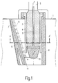
- FIG. 1 shows a high-voltage unit in the form of a high-voltage generator for an X-ray generator.
- the drawing shows only part of the high-voltage generator, namely a metal-grounded wall 1 of a housing, which includes all components of the high-voltage generator, including the liquid or gaseous insulating media.
- the high voltage generated is led to the outside via (at least) one cable 2 which is connected to the high voltage generator via a high voltage plug connection.
- the high-voltage plug connection comprises a cylindrical high-voltage plug 3 connected to the cable 2 and a hollow cylindrical high-voltage socket 4, which is firmly connected to the wall 1, the inner dimensions of which are adapted to the outer dimensions of the high-voltage plug 3.
- a high-voltage line 5 (or several lines at approximately the same high-voltage potential), which is connected through the bottom of the high-voltage socket to the other components, not shown, inside the high-voltage generator.
- the high-voltage line 5 is also referred to below as a high-voltage electrode.
- An X-ray emitter (not shown in more detail) is connected to the high-voltage generator via the cable 2 (and possibly via a further cable that carries a high voltage with opposite polarity).
- the high voltage generator is part of an x-ray generator together with the low voltage unit that feeds it.
- the high-voltage plug connection is - at least partially - enclosed by an insulating part 6.
- the insulating part 6 can be made of a thermosetting or thermoplastic, e.g. Polycarbonate.
- a voltage of a few volts prevails between the housing wall 1 and the measuring electrode 7 during operation.
- an electric field is formed between the high-voltage conductor 5 and the measuring electrode 7.
- a measuring divider resistor arrangement is located in this field-filled space. In an embodiment intended for 110 kV, this consists of 2 ⁇ 10 discrete resistors 8 of z. B. 26.7 Mohm each.
- One connection of this resistance chain is connected to the high-voltage electrode 5 and the other connection to the measuring electrode 7.
- the resistors 8 are arranged in a zigzag shape on a printed circuit board 9, which is opposite the electrodes 5 and 7 is inclined so that the end connected to the measuring electrode 7 is closer to the measuring electrode and the end connected to the high-voltage electrode is closer to the high-voltage electrode than the other end.
- This purpose is also served by a bell-shaped shield electrode 10, which carries the high-voltage potential and is connected to the conductor 5 and which reduces the dielectric field strength to a defined value at the end of the high-voltage plug connection and in the region of the end of the measuring divider resistor arrangement connected to it.
- the printed circuit board 9 is inserted into a groove 11 on the insulating part 6, which is formed between two longitudinally extending projections 12 on the insulating part 6.
- Fig. 3 shows the equivalent circuit diagram of the high-voltage measuring divider.
- the measuring electrode 7 is conductively connected to a measuring point 13, which is connected to earth via a base resistor consisting of an ohmic resistor 14 and a capacitor 15 parallel to it.
- the resistor 14 is a factor of 1000 smaller than each of the twenty resistors 8, so that (for direct current) there is a voltage divider factor of 1:20,000. If a voltage of, for example, a maximum of 110 kV is present at the electrode 5, then a voltage of 5.5 V is accordingly present at the measuring point 13.
- the base resistor 14, 15 can be arranged outside the high-voltage generator, the voltage tapped at it being fed to an amplifier (not shown in more detail).
- the capacitor 15 is dimensioned such that for high frequencies, at which the capacitive current is large compared to the current through the ohmic resistors 8, the same divisor factor results as for DC voltage.
- the capacitive current is essentially determined by the capacitance 16 that results between the high-voltage electrode 5 and the measuring electrode 7.
- the capacitance 16 should be as large as possible.
- the capacitance 16 can - if necessary - be increased in that the measuring electrode 7 extends over a larger part of the outer surface of the insulating part 6; if necessary, the measuring electrode can cover the entire outer surface.
- the measuring electrode 7 shields the measuring divider resistor arrangement 8 against earth. There is therefore not - as in the measuring divider according to EP-OS 118 147 parasitic capacitances between the resistor 8 and earth but only between this arrangement and the measuring electrode 7. Therefore the currents do not flow through these parasitic capacitances through the housing 1, but via the measuring electrode 7 and thus also via the base resistance 14, 15. So you go into the measurement.
- Another advantage of the invention is that a high-voltage component which is required anyway in the high-voltage generator also serves as a high-voltage electrode for the measuring divider, which reduces the costs and the space requirement.
- the high voltage divider is inside and not outside. The distances from the components inside the high-voltage generator that do not carry the same high voltage can therefore be reduced.
- the measuring electrode reduces the electromagnetic radiation emitted from the high-voltage electrode into other lines and components.
- the high-voltage connector 3, 4 has the advantage, however, that the insulation of the high-voltage electrode is already present, ie no additional insulation has to be provided between the measuring divider resistor arrangement 8, in particular its end connected to the measuring electrode 7 and the high-voltage electrode.
- the measuring resistor arrangement can also comprise a thick-film circuit or thin-film circuit applied to the plate 9.
- the high voltage divider can at its base, i.e. between the measuring point and earth, be connected differently than shown in Fig. 3.
- a series RC element can also be connected in parallel to the RC element 14, 15. With appropriate dimensioning of this series RC element, the frequency independence of the voltage divider factor can possibly be further improved.
Landscapes
- Physics & Mathematics (AREA)
- General Physics & Mathematics (AREA)
- Measuring Instrument Details And Bridges, And Automatic Balancing Devices (AREA)
- Measurement Of Current Or Voltage (AREA)
- Measurement Of Resistance Or Impedance (AREA)
Applications Claiming Priority (2)
| Application Number | Priority Date | Filing Date | Title |
|---|---|---|---|
| DE4211944 | 1992-04-09 | ||
| DE4211944A DE4211944A1 (de) | 1992-04-09 | 1992-04-09 | Hochspannungseinheit mit einer Meßteiler-Widerstandsanordnung |
Publications (3)
| Publication Number | Publication Date |
|---|---|
| EP0565204A2 true EP0565204A2 (fr) | 1993-10-13 |
| EP0565204A3 EP0565204A3 (fr) | 1994-08-03 |
| EP0565204B1 EP0565204B1 (fr) | 1999-07-07 |
Family
ID=6456470
Family Applications (1)
| Application Number | Title | Priority Date | Filing Date |
|---|---|---|---|
| EP93201023A Expired - Lifetime EP0565204B1 (fr) | 1992-04-09 | 1993-04-07 | Unité haute tension avec un diviseur de mesure à résistances |
Country Status (5)
| Country | Link |
|---|---|
| US (1) | US5408236A (fr) |
| EP (1) | EP0565204B1 (fr) |
| JP (1) | JP3438907B2 (fr) |
| CA (1) | CA2093774C (fr) |
| DE (2) | DE4211944A1 (fr) |
Cited By (3)
| Publication number | Priority date | Publication date | Assignee | Title |
|---|---|---|---|---|
| DE4412784A1 (de) * | 1994-04-18 | 1995-10-26 | Abb Patent Gmbh | Strom- und Spannungssensor für ein Hochspannungsschaltfeld und Hochspannungsschaltfeld mit einem solchen Strom- und Spannungssensor |
| EP0766373A1 (fr) * | 1995-09-30 | 1997-04-02 | Philips Patentverwaltung GmbH | Générateur de haute tension |
| DE19841164A1 (de) * | 1998-09-09 | 2000-03-16 | Abb Research Ltd | Spannungsteileranordnung |
Families Citing this family (14)
| Publication number | Priority date | Publication date | Assignee | Title |
|---|---|---|---|---|
| US6661017B1 (en) * | 2002-05-29 | 2003-12-09 | Ibis Technology Corporation | Ion implantation system having an energy probe |
| FR2858887B1 (fr) * | 2003-08-14 | 2005-09-23 | Ge Med Sys Global Tech Co Llc | Dispositif de production d'une haute tension comportant une resistance interne de mesure |
| US7498696B2 (en) * | 2004-11-20 | 2009-03-03 | General Electric Company | Voltage grading and shielding method for a high voltage component in a PCB and an X-ray apparatus |
| CN100399034C (zh) * | 2005-08-31 | 2008-07-02 | 东南大学 | 高压脉冲电阻分压器 |
| CN101074972B (zh) * | 2006-05-15 | 2010-05-12 | 北京瑞恒超高压电器研究所 | 一种电容屏蔽式电阻传感器 |
| US8063649B2 (en) * | 2009-04-03 | 2011-11-22 | Ut-Battelle, Llc | Broadband high impedance pickoff circuit |
| DE102012211989A1 (de) * | 2012-07-10 | 2014-01-16 | Siemens Aktiengesellschaft | E-Feld angepasste Anordnung von Bauteilen eines Spannungsteilers |
| EP2696206B1 (fr) * | 2012-08-06 | 2023-11-01 | ABB Schweiz AG | Agencement de moyenne ou haute tension présentant une borne de connexion de câble |
| CN103743926B (zh) * | 2013-12-24 | 2016-04-06 | 浙江大学 | 一种独立式微分-积分高压探头 |
| KR200482034Y1 (ko) * | 2016-03-18 | 2016-12-07 | 주식회사 니프코코리아 | 암 레스트의 유동방지구조 |
| US10129973B2 (en) | 2016-06-17 | 2018-11-13 | General Electric Company | Voltage divider circuit assembly and method |
| CN106199117B (zh) * | 2016-07-15 | 2018-11-23 | 中国南方电网有限责任公司超高压输电公司检修试验中心 | 一种直流分压器辅助伞裙设计方法 |
| CN112074068B (zh) * | 2020-09-28 | 2025-06-03 | 武汉联影医疗科技有限公司 | 高压发生器及x射线设备 |
| US11638345B2 (en) * | 2021-04-05 | 2023-04-25 | Fluke Corporation | Feed forward compensation of parasitic capacitance in a device frontend |
Family Cites Families (12)
| Publication number | Priority date | Publication date | Assignee | Title |
|---|---|---|---|---|
| US3449668A (en) * | 1965-03-15 | 1969-06-10 | Sweeney Mfg Co B K | Portable static meter for determining the magnitude and polarity of accumulated electrostatic charges |
| US4189673A (en) * | 1978-05-01 | 1980-02-19 | Burroughs Corporation | Pen-shaped precision multi-level current mode logic test probe |
| DE2833036C2 (de) * | 1978-07-25 | 1980-09-11 | Siemens Ag, 1000 Berlin Und 8000 Muenchen | Spannungsmeßeinrichtung für gas- oder flüssigkeitsisolierte Hochspannungsschaltanlagen |
| US4418314A (en) * | 1980-10-20 | 1983-11-29 | The United States Of America As Represented By The Secretary Of The Army | High impedance fast voltage probe |
| DE3304316A1 (de) * | 1983-02-09 | 1984-08-09 | Philips Patentverwaltung Gmbh, 2000 Hamburg | Mess- und daempfungswiderstandsanordnung fuer ein hochspannungsgeraet |
| DE3714945A1 (de) * | 1986-05-09 | 1987-11-12 | Koch & Sterzel Kg | Frequenzunabhaengiger kapazitiv-ohmscher spannungsteiler zum messen von hochspannungen in mittel- und hochfrequenten roentgengeneratoren |
| US4950978A (en) * | 1988-12-08 | 1990-08-21 | Airborne Research Associates, Inc. | Atmospheric potential measurement device |
| DE3902263A1 (de) * | 1989-01-26 | 1990-08-02 | Philips Patentverwaltung | Anordnung zur hochspannungsmessung |
| US5134364A (en) * | 1990-06-19 | 1992-07-28 | Prime Computer, Inc. | Elastomeric test probe |
| US5105181A (en) * | 1990-08-17 | 1992-04-14 | Hydro-Quebec | Method and electrical measuring apparatus for analyzing the impedance of the source of an actual alternating voltage |
| US5107201A (en) * | 1990-12-11 | 1992-04-21 | Ogle John S | High voltage oscilloscope probe with wide frequency response |
| US5256979A (en) * | 1992-02-21 | 1993-10-26 | Abb Power T&D Company Inc. | Method and apparatus for measuring an unknown voltage, and power meter employing the same |
-
1992
- 1992-04-09 DE DE4211944A patent/DE4211944A1/de not_active Withdrawn
-
1993
- 1993-04-07 EP EP93201023A patent/EP0565204B1/fr not_active Expired - Lifetime
- 1993-04-07 DE DE59309681T patent/DE59309681D1/de not_active Expired - Fee Related
- 1993-04-08 CA CA002093774A patent/CA2093774C/fr not_active Expired - Fee Related
- 1993-04-09 US US08/045,843 patent/US5408236A/en not_active Expired - Lifetime
- 1993-04-09 JP JP08349793A patent/JP3438907B2/ja not_active Expired - Fee Related
Cited By (3)
| Publication number | Priority date | Publication date | Assignee | Title |
|---|---|---|---|---|
| DE4412784A1 (de) * | 1994-04-18 | 1995-10-26 | Abb Patent Gmbh | Strom- und Spannungssensor für ein Hochspannungsschaltfeld und Hochspannungsschaltfeld mit einem solchen Strom- und Spannungssensor |
| EP0766373A1 (fr) * | 1995-09-30 | 1997-04-02 | Philips Patentverwaltung GmbH | Générateur de haute tension |
| DE19841164A1 (de) * | 1998-09-09 | 2000-03-16 | Abb Research Ltd | Spannungsteileranordnung |
Also Published As
| Publication number | Publication date |
|---|---|
| US5408236A (en) | 1995-04-18 |
| DE4211944A1 (de) | 1993-10-14 |
| DE59309681D1 (de) | 1999-08-12 |
| JPH0650996A (ja) | 1994-02-25 |
| EP0565204B1 (fr) | 1999-07-07 |
| EP0565204A3 (fr) | 1994-08-03 |
| JP3438907B2 (ja) | 2003-08-18 |
| CA2093774C (fr) | 2001-03-06 |
| CA2093774A1 (fr) | 1993-10-10 |
Similar Documents
| Publication | Publication Date | Title |
|---|---|---|
| EP0565204B1 (fr) | Unité haute tension avec un diviseur de mesure à résistances | |
| DE3809503C2 (de) | Kondensatorschaltung für einen Impulsgenerator | |
| DE2608430C3 (de) | Halterung für programmierbare Sonden zum Anschluß an ein in einer elektrischen Prüfung befindliches Bauteil | |
| DE2824144C2 (de) | Einrichtung zur kapazitiven Niveauhöhenmessung von Flüssigkeiten oder Feststoffen | |
| EP0118147B1 (fr) | Dispositif de résistance de mesure et d'amortissement pour un appareil à haute tension | |
| EP0134187A2 (fr) | Dispositif de mesure pour détecter des décharges partielles dans des dispositifs commutateurs à haute tension dans un boîtier métallique isolé par gaz sous pression | |
| DE102006061923A1 (de) | Rogowski-Sensor und Verfahren zum Messen eines Stromes | |
| DE3714945C2 (fr) | ||
| DE19841164A1 (de) | Spannungsteileranordnung | |
| EP0639940A1 (fr) | Circuit de commande pour un véhicule | |
| EP0464021B1 (fr) | Dispositif de mesure a electrode auxiliaire pour installations a haute tension blindees isolees au gaz | |
| DE19855528A1 (de) | Kapazitiver Spannungsteiler | |
| DE3731394C2 (de) | Hochfrequenz-Entstörfilter für eine an eine Leitung anzuschließende Schaltung, insbesondere für Zweidraht-Sensoren | |
| DE3216285C2 (de) | Impulsgenerator mit einer Gleichspannungsquelle | |
| DE10113912A1 (de) | Elektronische Vorrichtung | |
| DE715477C (de) | Aus koaxialen Leitern gebildeter abgestimmter Kreis | |
| DE19640359C1 (de) | Antennenanordnung für ein diagnostisches Magnetresonanzgerät | |
| WO2001022537A1 (fr) | Dispositif de contacts a ressort dans une trame predeterminee | |
| EP0810815B1 (fr) | Appareil de radiographie | |
| DE2618163C2 (de) | Spulenanordnung für Näherungsschalter | |
| DE3242621A1 (de) | Kapazitiver annaeherungsmelder | |
| DE4327850C2 (de) | Planarfilter insbesondere für mehrpolige Steckverbinder mit Stecker und Gegenstecker | |
| DE2948365A1 (de) | Ruecklauftransformator | |
| DE102013005340A1 (de) | Elektrische Verbindung mit kapazitiver Kopplung | |
| DE10056988A1 (de) | Spannungsteileranordnung |
Legal Events
| Date | Code | Title | Description |
|---|---|---|---|
| PUAI | Public reference made under article 153(3) epc to a published international application that has entered the european phase |
Free format text: ORIGINAL CODE: 0009012 |
|
| AK | Designated contracting states |
Kind code of ref document: A2 Designated state(s): DE FR GB |
|
| PUAL | Search report despatched |
Free format text: ORIGINAL CODE: 0009013 |
|
| AK | Designated contracting states |
Kind code of ref document: A3 Designated state(s): DE FR GB |
|
| RAP1 | Party data changed (applicant data changed or rights of an application transferred) |
Owner name: N.V. PHILIPS' GLOEILAMPENFABRIEKEN Owner name: PHILIPS PATENTVERWALTUNG GMBH |
|
| 17P | Request for examination filed |
Effective date: 19950203 |
|
| 17Q | First examination report despatched |
Effective date: 19970828 |
|
| GRAG | Despatch of communication of intention to grant |
Free format text: ORIGINAL CODE: EPIDOS AGRA |
|
| RAP3 | Party data changed (applicant data changed or rights of an application transferred) |
Owner name: KONINKLIJKE PHILIPS ELECTRONICS N.V. Owner name: PHILIPS PATENTVERWALTUNG GMBH |
|
| GRAG | Despatch of communication of intention to grant |
Free format text: ORIGINAL CODE: EPIDOS AGRA |
|
| GRAH | Despatch of communication of intention to grant a patent |
Free format text: ORIGINAL CODE: EPIDOS IGRA |
|
| GRAH | Despatch of communication of intention to grant a patent |
Free format text: ORIGINAL CODE: EPIDOS IGRA |
|
| GRAA | (expected) grant |
Free format text: ORIGINAL CODE: 0009210 |
|
| AK | Designated contracting states |
Kind code of ref document: B1 Designated state(s): DE FR GB |
|
| PG25 | Lapsed in a contracting state [announced via postgrant information from national office to epo] |
Ref country code: FR Free format text: LAPSE BECAUSE OF FAILURE TO SUBMIT A TRANSLATION OF THE DESCRIPTION OR TO PAY THE FEE WITHIN THE PRESCRIBED TIME-LIMIT Effective date: 19990707 |
|
| REF | Corresponds to: |
Ref document number: 59309681 Country of ref document: DE Date of ref document: 19990812 |
|
| GBT | Gb: translation of ep patent filed (gb section 77(6)(a)/1977) |
Effective date: 19990909 |
|
| EN | Fr: translation not filed | ||
| RAP4 | Party data changed (patent owner data changed or rights of a patent transferred) |
Owner name: KONINKLIJKE PHILIPS ELECTRONICS N.V. Owner name: PHILIPS CORPORATE INTELLECTUAL PROPERTY GMBH |
|
| PLBE | No opposition filed within time limit |
Free format text: ORIGINAL CODE: 0009261 |
|
| STAA | Information on the status of an ep patent application or granted ep patent |
Free format text: STATUS: NO OPPOSITION FILED WITHIN TIME LIMIT |
|
| 26N | No opposition filed | ||
| REG | Reference to a national code |
Ref country code: GB Ref legal event code: IF02 |
|
| REG | Reference to a national code |
Ref country code: GB Ref legal event code: 746 Effective date: 20021025 |
|
| PGFP | Annual fee paid to national office [announced via postgrant information from national office to epo] |
Ref country code: GB Payment date: 20030430 Year of fee payment: 11 |
|
| PG25 | Lapsed in a contracting state [announced via postgrant information from national office to epo] |
Ref country code: GB Free format text: LAPSE BECAUSE OF NON-PAYMENT OF DUE FEES Effective date: 20040407 |
|
| GBPC | Gb: european patent ceased through non-payment of renewal fee | ||
| PGFP | Annual fee paid to national office [announced via postgrant information from national office to epo] |
Ref country code: DE Payment date: 20080617 Year of fee payment: 16 |
|
| PG25 | Lapsed in a contracting state [announced via postgrant information from national office to epo] |
Ref country code: DE Free format text: LAPSE BECAUSE OF NON-PAYMENT OF DUE FEES Effective date: 20091103 |