EP0565329A2 - Abgeschirmter elektrischer Verbinder - Google Patents
Abgeschirmter elektrischer Verbinder Download PDFInfo
- Publication number
- EP0565329A2 EP0565329A2 EP93302659A EP93302659A EP0565329A2 EP 0565329 A2 EP0565329 A2 EP 0565329A2 EP 93302659 A EP93302659 A EP 93302659A EP 93302659 A EP93302659 A EP 93302659A EP 0565329 A2 EP0565329 A2 EP 0565329A2
- Authority
- EP
- European Patent Office
- Prior art keywords
- electrical connector
- contacts
- connector
- contact
- isolation
- Prior art date
- Legal status (The legal status is an assumption and is not a legal conclusion. Google has not performed a legal analysis and makes no representation as to the accuracy of the status listed.)
- Withdrawn
Links
Images


Classifications
-
- H—ELECTRICITY
- H01—ELECTRIC ELEMENTS
- H01R—ELECTRICALLY-CONDUCTIVE CONNECTIONS; STRUCTURAL ASSOCIATIONS OF A PLURALITY OF MUTUALLY-INSULATED ELECTRICAL CONNECTING ELEMENTS; COUPLING DEVICES; CURRENT COLLECTORS
- H01R13/00—Details of coupling devices of the kinds covered by groups H01R12/70 or H01R24/00 - H01R33/00
- H01R13/648—Protective earth or shield arrangements on coupling devices, e.g. anti-static shielding
- H01R13/658—High frequency shielding arrangements, e.g. against EMI [Electro-Magnetic Interference] or EMP [Electro-Magnetic Pulse]
- H01R13/6581—Shield structure
- H01R13/6582—Shield structure with resilient means for engaging mating connector
-
- H—ELECTRICITY
- H01—ELECTRIC ELEMENTS
- H01R—ELECTRICALLY-CONDUCTIVE CONNECTIONS; STRUCTURAL ASSOCIATIONS OF A PLURALITY OF MUTUALLY-INSULATED ELECTRICAL CONNECTING ELEMENTS; COUPLING DEVICES; CURRENT COLLECTORS
- H01R13/00—Details of coupling devices of the kinds covered by groups H01R12/70 or H01R24/00 - H01R33/00
- H01R13/648—Protective earth or shield arrangements on coupling devices, e.g. anti-static shielding
- H01R13/658—High frequency shielding arrangements, e.g. against EMI [Electro-Magnetic Interference] or EMP [Electro-Magnetic Pulse]
- H01R13/6581—Shield structure
- H01R13/6585—Shielding material individually surrounding or interposed between mutually spaced contacts
- H01R13/6586—Shielding material individually surrounding or interposed between mutually spaced contacts for separating multiple connector modules
Definitions
- the present invention relates to an electrical connector, more specifically to a shielded electrical connector having an electrically conductive shell for shielding purposes.
- Ashielded electrical connector is essential to the prevention the transmission of electrical noise from or to electronic machines to be used close to one another, especially in signal transmission or interface of digital equipment. Since regulations involving electromagnetic interference (EMI) are increasingly more strict, needs for such shielded electrical connectors are growing rapidly.
- EMI electromagnetic interference
- a shielded electrical connector is normally used with a flat or circular shielded cable and the shield or ground wires of such cable are electrically connected to a shielded electrically conductive shell essentially covering or enclosing the outside of such shielded electrical connector.
- the electrically conductive shell is usually connected to an electrically conductive panel or ground conductor layer on a circuit board of the electronic equipment using such a connector.
- a typical conductive shell of a conventional shielded electrical connector is disclosed in, for example, Japanese UM Pub. No. 39901/'91 and is configured by advantageously stamping and forming an electrically conductive metal plate in such a manner as to cover the mating portion of an insulating housing, and also to be connected to a ground conductor of a circuit board.
- Japanese Patent Pub. No. 17736/71 discloses a shielded electrical connector in which an electrically conductive layer is advantageously formed on the outer surface of an insulating housing to isolate and retain a large number of contacts.
- the known shielded electrical connectors have a disadvantage because they use a metal plate which does not cover the whole outer surface of the connector, thereby making it difficult to obtain perfect shielding, and it is further very complicated and expensive to assemble the shielding member and the insulating housing. Additionally, the connector adopting the latter shielding approach has a disadvantage in applications involving a high frequency shielded electrical connectors. Also, conventional shielded electrical connectors experience difficulty in directly connecting ground terminals to the electrically conductive shell.
- the shielded electrical connector uses a metal die-cast material as the electrically conductive shell.
- the cavity inside of the die-cast shell is divided by an isolation wall made of an electrically conductive metal plate.
- Discrete connector modules are received and retained in divided cavities for shielding between the rows of contacts of the connector modules as well as for establishing a micro- stripline structure suited for high frequency signal transmission.
- the shielded electrical connector has a cavity of an electrically conductive shell divided by an isolation wall of an electrically conductive metal plate along which signal and ground contacts are disposed.
- the ground contacts are directly contacted to the isolation wall through openings in the insulating housing at the side of the isolation wall, thereby allowing optimum grounding of the ground contacts.
- both signal and ground contacts are identical to each other and only the orientation of such contacts is changed.
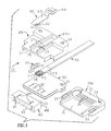
- FIG. 1 Illustrated in FIG. 1 is an exploded perspective view of a preferred embodiment of the shielded electrical connector 10 according to the present invention.
- the shielded electrical connector 10 comprises: a two-piece die-cast, electrically conductive shell 20; an isolation metal plate 30; an insulating housing 40; a pair of right and left key members 50; a latch member 60; and a plurality of fiat cables 70 (only one cable 70 is shown in FIG. 1.)
- the electrically conductive shell 20 comprises an upper shell 20a and a lower shell 20b. Both shells 20a, 20b are essentially similar in shape and dimension. However, they differ in that the bottom surface of the lower shell 20b is generally flat while additional structures are provided on the upper surface of the uppershell for mounting a latch member60.
- the electrically conductive shell 20 has a recess 21 to define a cavity at the front center portion for receiving the insulating housing 40 and the metal isolation wall 30. At both sides of the recess 21, there are keyways 22, 23 for receiving the pair of key members 50. Screw holes 24 are formed in both shells 20a, 20b near the rear end of the electrically conductive shell 20 for screw mounting both shells 20a, 20b.
- the electrically conductive shell 20 has a raised floor surface 25 at the rear portion of the recess 21 on the surface of which a plurality of ribs 26 are formed (3 rows in the shown preferred embodiment). As described in detail hereinafter, the ribs 26 act as a strain relief for the cable 70 of each connector module.
- a pair of generally parallel rails 27 are formed in the upper surface of the upper shell 20a from the front end toward the rear end at the center portion thereof for inserting and mounting one end of the latch member 60 in mounting holes 29 in a recess 28 between the rails 27.
- the key member 50 may be a rod-like member made from, for example, octagonal stock and is preferably made from a light metal. Acut-away portion 52 is formed atthe front end of a center portion 51 so that only a selected matable connector (not shown) having the complementary key member will mate with the connector. The function of the key member 50 will be described hereinafter.
- the metal isolation walls 30 are a pair of essentially identical metal plates for placing in the shells 20a, 20b. Circular holes 31 are bored near the back end of each isolation wall 30 at locations corresponding to the screw holes 24 in the shell 20 for integrating the both shells 20a, 20b by bolts. A plurality of ribs 32 are formed near the front end of each isolation wall 30.
- the latch member 50 may be identical to the latch arm made by stamping and forming a resilient metal plate as is disclosed in Japanese UM laid-open no. 116674/91. That is, a pair of mounting ears 62 at both sides of the free end of a lower leg 61 of a generally V-shaped latch arm are inserted and secured in the mounting holes 29 in the uppershell 20a.
- An upperleg 63 is longer than the lower leg 61 and extends backwardly from the mating (or front) end at an angle.
- An operation portion 64 is formed at the free end of the upper leg 63.
- a cable 70 is a flat cable known as the STAR cable and comprises, for example, a pair of signal conductors at each side of a center ground conductor and covered with an insulator.
- a plurality of contacts e.g., receptacle or female contacts
- a hot melt technique to constitute a connector module 75 as described hereinafter.
- Disposed at the front portion of the electrically conductive shell 20 is an insulating housing or a cover housing 40 to be secured over the aforementioned base housing 76 of the module 75.
- the cover housing 40 contains two rows of contact insertion openings 41 and a recess (not shown) for receiving the base housing 76 of module 75 from the rear face toward the front face.
- a plurality of ribs 44 may be formed on the upper surface 42 and the lower surface 43 of the cover housing 40 for interference fitting with engaging channels (not shown) in the innerwalls of the recess 21 of the electrically conductive shell 20 for retention purposes.
- the latch member 60 is secured onto the upper shell 20a and the key members 50 are inserted into the keyways 22, 23 in the lower shell 20b in a selected orientation.
- the cover housing 40 is then positioned at the front portion of the recess 21 in the electrically conductive shell 20.
- a desired number of cables 70 are arranged on the lower shell 20b so that the connector modules 75 are accommodated in the recess of the cover housing 40.
- the two metal isolation walls 30 are disposed in back-to-back manner.
- cables 70 are terminated to a plurality of connector modules 75 and are arranged on the upper isolation wall 30.
- both shells 20a, 20b are integrated using bolts to complete the shielded electrical connector 10.
- FIG. 2 Illustrated in FIG. 2 is a cross sectional view of a pair of connector modules 75 terminated to the ends of the cables 70 shown in FIG. 1 and disposed on both sides of the isolation walls 30. Since the connector modules 75a, 75b disposed on the upper and lower sides of the stacked isolation walls 30a, 30b are symmetrical, only the upper connector module 75a will be described herein.
- the connector modules 75a comprise: the base housing 76 having a plurality of contacts terminated to one end of the cable 70 containing a total of five conductors; or two signal conductors at each side of the center ground conductor, and secured by a plastic material 73 formed by a so-called hot melt technique.
- Each connector module 75 is positioned in such a manner that the center or the ground conductor 78 is aligned with one of the ribs 32 on the isolation wall 30.
- the base housing 76 is provided with total five channels 79, one open downwardly at the position corresponding to the ground contact 78, and four open upwardly at both sides and the positions corresponding to the four signal contacts 77.
- each signal contact 77 is generally U-shaped in cross-section and has a pair of resilient contact portions 77a, 77b formed by inwardly deforming both sidewalls and also a cantilever type resilient strip 77c is formed by cutting, raising and outwardly bending the bottom surface of the U-shaped portion.
- the ground contact 78 has resilient contact portions 78a, 78b at both sides and a resilient strip 78c on the bottom surface.
- the resilient strip 78c of the ground contact 78 is constructed to resiliently engage the rib 32 on the isolation wall 30. That is, the channel 79 for the ground contact 78, and the rib 32 on the isolation wall 30, constitute alignment and guide portions and the shortest and most direct electrical engagement therebetween.
- FIG. 3 is a cross sectional view of the cover housing and the electrically conductive shield 20 assembled as the connector modules 75a, 75b in FIG. 2, wherein the upper and lower halves 20a, 20b show the cross sectional views at the ground contact 78 and the signal contact 77 positions, respectively.
- Each signal conductor 71 of the cables 70a, 70b is welded to the respective signal contact 77, while each ground conductor 72 is connected to the ground contact 78.
- the end portion of the cable 70 including the weld junction portions is integrally molded with plastic material 73 by a hot-melt technique. As is apparent in FIG.
- the resilient strip 78c of the ground contact 78 deflects and biasingly engages the rib 32 on the isolation wall 30 fora ground connection, thereby helping to support the ground contact 78 and aligning the aperture 41 with the ground contact 78 for insertion of a termination post.
- the resilient strip 77c of each signal contact 77 engages insulating rib 43 in a recess 46 at the rear portion of the cover housing 40, thereby deflecting and pressing the signal contact 77 toward the isolation wall 30, thereby helping to support the signal contact 77 and aligning the aperture with the contact 77 for insert of a termination post.
- Astep portion 44 followed by the tapered portion near the rear end of the recess 42 in the cover housing 40 acts to retain the base housing 76 received in the recess 46.
- a wave portion 26 is formed on the inner wall of the electrically conductive shell 20 at a remote location from the cable 70, and constitutes a strain relief for the cable 70 by grabbing the jacket thereof.
- a wave portion 33 is also formed in the isolation wall 30 at the corresponding location to the wave portion 26 in the shell 20. Both wave portions 26 and 33 provide sufficient strain relief for the cable 70 to prevent electrical discontinuity due to overstress to the welded portions.
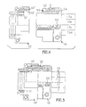
- FIGS. 4-5 illustrate an example of a matable connector 10' to be used with the shielded electrical connector 10 of the present invention.
- FIG. 4 shows both connectors 10, 10' in the un-mated or separated condition
- FIG. 5 is a plan viewof the connectors 10, 10' in the mated condition.
- the cut-away portions of the key members 50, 50' are made complementary to each other so that only particular connectors can mate to each other (see FIG. 5), thereby avoiding any danger of accidentally mating a connector having an unmatching key program.
- the assembled shielded electrical connector 10 can be disassembled by loosening the bolts to disintegrate the electrically conductive shell 20 for modifying the key of the key member 50 and replacement or rearrangement of the cables 70 in the connector module 75.
- FIGS. 6-7 illustrate an example of the contact 77, 78 to be used in the present invention.
- FIG. 6 is a plan view while FIG. 7 is a side view.
- the contact can be made by stamping and forming a metal plate.
- both contacts 77, 78 are identical as mentioned hereinbefore, a brief description is made hereunder about the signal contact 77 for convenience.
- the contact 77 comprises the forward portion and the rear portion of a generally U-shaped cross-section.
- the sidewalls between ends are bent toward each other to provide resilient contact portions 77a, 77b.
- the bottom surface is cut and raised from the front to the rear portion and bent outwardly in " ⁇ " shape to form the cantilever type resilient strip 77c.
- the matable connector 10' in FIG. 4 has, for example, rectangular post contacts for establishing electrical contact between the contact portions 77a, 77b. It is, of course, possible that the contact shape can be circular or any other shape.
Landscapes
- Details Of Connecting Devices For Male And Female Coupling (AREA)
Applications Claiming Priority (2)
| Application Number | Priority Date | Filing Date | Title |
|---|---|---|---|
| JP4113144A JPH05290931A (ja) | 1992-04-07 | 1992-04-07 | シールド型電気コネクタ |
| JP113144/92 | 1992-04-07 |
Publications (2)
| Publication Number | Publication Date |
|---|---|
| EP0565329A2 true EP0565329A2 (de) | 1993-10-13 |
| EP0565329A3 EP0565329A3 (en) | 1995-04-26 |
Family
ID=14604689
Family Applications (1)
| Application Number | Title | Priority Date | Filing Date |
|---|---|---|---|
| EP93302659A Withdrawn EP0565329A3 (en) | 1992-04-07 | 1993-04-05 | Shielded electrical connector |
Country Status (3)
| Country | Link |
|---|---|
| US (1) | US5269703A (de) |
| EP (1) | EP0565329A3 (de) |
| JP (1) | JPH05290931A (de) |
Families Citing this family (5)
| Publication number | Priority date | Publication date | Assignee | Title |
|---|---|---|---|---|
| US5882227A (en) * | 1997-09-17 | 1999-03-16 | Intercon Systems, Inc. | Controlled impedance connector block |
| US6000955A (en) * | 1997-12-10 | 1999-12-14 | Gabriel Technologies, Inc. | Multiple terminal edge connector |
| US7004793B2 (en) * | 2004-04-28 | 2006-02-28 | 3M Innovative Properties Company | Low inductance shielded connector |
| US8888530B2 (en) * | 2013-02-26 | 2014-11-18 | Tyco Electronics Corporation | Grounding structures for contact modules of connector assemblies |
| CN116171511B (zh) * | 2020-08-26 | 2026-04-03 | 住友电装株式会社 | 成型连接器 |
Family Cites Families (11)
| Publication number | Priority date | Publication date | Assignee | Title |
|---|---|---|---|---|
| US3864011A (en) * | 1973-08-27 | 1975-02-04 | Amp Inc | Coaxial ribbon cable connector |
| US4094564A (en) * | 1977-03-17 | 1978-06-13 | A P Products Incorporated | Multiple conductor electrical connector with ground bus |
| US4157612A (en) * | 1977-12-27 | 1979-06-12 | Bell Telephone Laboratories, Incorporated | Method for improving the transmission properties of a connectorized flat cable interconnection assembly |
| EP0211496B1 (de) * | 1985-07-12 | 1993-01-13 | The Whitaker Corporation | Doppelreihiger elektrischer Verbinder |
| US4655515A (en) * | 1985-07-12 | 1987-04-07 | Amp Incorporated | Double row electrical connector |
| US4767345A (en) * | 1987-03-27 | 1988-08-30 | Amp Incorporated | High-density, modular, electrical connector |
| US5032089A (en) * | 1990-06-06 | 1991-07-16 | W. L. Gore & Associates, Inc. | Shielded connectors for shielded cables |
| US5030115A (en) * | 1990-07-23 | 1991-07-09 | Molex Incorporated | Tired socket assembly with integral ground shield |
| US5074806A (en) * | 1990-07-26 | 1991-12-24 | Amp Incorporated | Method and apparatus for coupling a connector to a cable |
| US5190464A (en) * | 1991-03-29 | 1993-03-02 | Chian Chyun Enterprise Co. Ltd. | Shielded electrical connector with contact shunting arrangement |
| GB2255863B (en) * | 1991-05-17 | 1995-05-03 | Minnesota Mining & Mfg | Connector for coaxial cables |
-
1992
- 1992-04-07 JP JP4113144A patent/JPH05290931A/ja active Pending
-
1993
- 1993-03-18 US US08/037,652 patent/US5269703A/en not_active Expired - Fee Related
- 1993-04-05 EP EP93302659A patent/EP0565329A3/en not_active Withdrawn
Also Published As
| Publication number | Publication date |
|---|---|
| EP0565329A3 (en) | 1995-04-26 |
| US5269703A (en) | 1993-12-14 |
| JPH05290931A (ja) | 1993-11-05 |
Similar Documents
| Publication | Publication Date | Title |
|---|---|---|
| CN111682366B (zh) | 背板连接器组件 | |
| EP0570181B1 (de) | Elektrischer Verbinder für Hochfrequenz | |
| US5588851A (en) | Connector for a cable for high frequency signals | |
| EP0523491B1 (de) | Modularer elektrischer Verbinder | |
| US5842872A (en) | Modular right angle board mountable coaxial connector | |
| US6478624B2 (en) | High speed connector | |
| US5620340A (en) | Connector with improved shielding | |
| US4838811A (en) | Modular connector with EMI countermeasure | |
| US5632634A (en) | High frequency cable connector | |
| US4653825A (en) | Shielded electrical connector assembly | |
| US5174770A (en) | Multicontact connector for signal transmission | |
| KR100320114B1 (ko) | 차폐형케이블용커넥터 | |
| US4682840A (en) | Electrical connection and method of making same | |
| US4386814A (en) | Kit for converting a panel opening to a shielded pin receptacle | |
| JP2539197Y2 (ja) | シールド式電気コネクターアセンブリ | |
| JP2911860B2 (ja) | 低プロフィールコネクタシステム | |
| US6210230B1 (en) | Cable connector | |
| US20020146926A1 (en) | Connector interface and retention system for high-density connector | |
| US5842887A (en) | Connector with improved shielding | |
| US20210044040A1 (en) | Cable assembly modules detachably mounted upon corresponding circuit pads | |
| EP0996993B1 (de) | Verriegelte und abgeschirmte elektrische verbinder | |
| EP0677215B1 (de) | Ein verbinder mit verbesserter abschirmung | |
| EP0108477A1 (de) | Kodierungssystem für Steckerfamilien | |
| US5269703A (en) | Shielded electrical connector | |
| US20250079735A1 (en) | Electrical connector assembly with improved mating interfaces |
Legal Events
| Date | Code | Title | Description |
|---|---|---|---|
| PUAI | Public reference made under article 153(3) epc to a published international application that has entered the european phase |
Free format text: ORIGINAL CODE: 0009012 |
|
| AK | Designated contracting states |
Kind code of ref document: A2 Designated state(s): DE FR GB NL |
|
| PUAL | Search report despatched |
Free format text: ORIGINAL CODE: 0009013 |
|
| AK | Designated contracting states |
Kind code of ref document: A3 Designated state(s): DE FR GB NL |
|
| STAA | Information on the status of an ep patent application or granted ep patent |
Free format text: STATUS: THE APPLICATION IS DEEMED TO BE WITHDRAWN |
|
| 18D | Application deemed to be withdrawn |
Effective date: 19951027 |