EP0565355B1 - Système optique à relais d'image - Google Patents
Système optique à relais d'image Download PDFInfo
- Publication number
- EP0565355B1 EP0565355B1 EP93302722A EP93302722A EP0565355B1 EP 0565355 B1 EP0565355 B1 EP 0565355B1 EP 93302722 A EP93302722 A EP 93302722A EP 93302722 A EP93302722 A EP 93302722A EP 0565355 B1 EP0565355 B1 EP 0565355B1
- Authority
- EP
- European Patent Office
- Prior art keywords
- refractive
- mirror
- optical element
- primary
- lenses
- Prior art date
- Legal status (The legal status is an assumption and is not a legal conclusion. Google has not performed a legal analysis and makes no representation as to the accuracy of the status listed.)
- Expired - Lifetime
Links
- 230000003287 optical effect Effects 0.000 title claims description 115
- 238000003384 imaging method Methods 0.000 title claims description 15
- 230000004075 alteration Effects 0.000 claims description 22
- 230000005855 radiation Effects 0.000 claims description 8
- 210000001747 pupil Anatomy 0.000 claims description 7
- 239000005331 crown glasses (windows) Substances 0.000 description 5
- 239000005308 flint glass Substances 0.000 description 5
- 239000000463 material Substances 0.000 description 5
- 230000003595 spectral effect Effects 0.000 description 5
- 239000011521 glass Substances 0.000 description 3
- 230000002349 favourable effect Effects 0.000 description 2
- 102100032305 Bcl-2 homologous antagonist/killer Human genes 0.000 description 1
- 101000798320 Homo sapiens Bcl-2 homologous antagonist/killer Proteins 0.000 description 1
- XUIMIQQOPSSXEZ-UHFFFAOYSA-N Silicon Chemical compound [Si] XUIMIQQOPSSXEZ-UHFFFAOYSA-N 0.000 description 1
- 239000003086 colorant Substances 0.000 description 1
- 230000007812 deficiency Effects 0.000 description 1
- 238000004519 manufacturing process Methods 0.000 description 1
- 238000000034 method Methods 0.000 description 1
- 230000004048 modification Effects 0.000 description 1
- 238000012986 modification Methods 0.000 description 1
- 229910052710 silicon Inorganic materials 0.000 description 1
- 239000010703 silicon Substances 0.000 description 1
Images



Classifications
-
- G—PHYSICS
- G02—OPTICS
- G02B—OPTICAL ELEMENTS, SYSTEMS OR APPARATUS
- G02B17/00—Systems with reflecting surfaces, with or without refracting elements
- G02B17/08—Catadioptric systems
- G02B17/0852—Catadioptric systems having a field corrector only
-
- G—PHYSICS
- G02—OPTICS
- G02B—OPTICAL ELEMENTS, SYSTEMS OR APPARATUS
- G02B17/00—Systems with reflecting surfaces, with or without refracting elements
- G02B17/08—Catadioptric systems
- G02B17/0804—Catadioptric systems using two curved mirrors
- G02B17/0812—Catadioptric systems using two curved mirrors off-axis or unobscured systems in which all of the mirrors share a common axis of rotational symmetry
-
- G—PHYSICS
- G02—OPTICS
- G02B—OPTICAL ELEMENTS, SYSTEMS OR APPARATUS
- G02B17/00—Systems with reflecting surfaces, with or without refracting elements
- G02B17/08—Catadioptric systems
- G02B17/082—Catadioptric systems using three curved mirrors
- G02B17/0832—Catadioptric systems using three curved mirrors off-axis or unobscured systems in which not all of the mirrors share a common axis of rotational symmetry, e.g. at least one of the mirrors is warped, tilted or decentered with respect to the other elements
-
- G—PHYSICS
- G02—OPTICS
- G02B—OPTICAL ELEMENTS, SYSTEMS OR APPARATUS
- G02B27/00—Optical systems or apparatus not provided for by any of the groups G02B1/00 - G02B26/00, G02B30/00
- G02B27/0025—Optical systems or apparatus not provided for by any of the groups G02B1/00 - G02B26/00, G02B30/00 for optical correction, e.g. distorsion, aberration
- G02B27/0037—Optical systems or apparatus not provided for by any of the groups G02B1/00 - G02B26/00, G02B30/00 for optical correction, e.g. distorsion, aberration with diffracting elements
-
- G—PHYSICS
- G02—OPTICS
- G02B—OPTICAL ELEMENTS, SYSTEMS OR APPARATUS
- G02B27/00—Optical systems or apparatus not provided for by any of the groups G02B1/00 - G02B26/00, G02B30/00
- G02B27/42—Diffraction optics, i.e. systems including a diffractive element being designed for providing a diffractive effect
- G02B27/4205—Diffraction optics, i.e. systems including a diffractive element being designed for providing a diffractive effect having a diffractive optical element [DOE] contributing to image formation, e.g. whereby modulation transfer function MTF or optical aberrations are relevant
- G02B27/4211—Diffraction optics, i.e. systems including a diffractive element being designed for providing a diffractive effect having a diffractive optical element [DOE] contributing to image formation, e.g. whereby modulation transfer function MTF or optical aberrations are relevant correcting chromatic aberrations
-
- G—PHYSICS
- G02—OPTICS
- G02B—OPTICAL ELEMENTS, SYSTEMS OR APPARATUS
- G02B27/00—Optical systems or apparatus not provided for by any of the groups G02B1/00 - G02B26/00, G02B30/00
- G02B27/42—Diffraction optics, i.e. systems including a diffractive element being designed for providing a diffractive effect
- G02B27/4205—Diffraction optics, i.e. systems including a diffractive element being designed for providing a diffractive effect having a diffractive optical element [DOE] contributing to image formation, e.g. whereby modulation transfer function MTF or optical aberrations are relevant
- G02B27/4216—Diffraction optics, i.e. systems including a diffractive element being designed for providing a diffractive effect having a diffractive optical element [DOE] contributing to image formation, e.g. whereby modulation transfer function MTF or optical aberrations are relevant correcting geometrical aberrations
Definitions
- This invention relates to re-imaging optical systems and, more particularly, to a catatrioptric re-imaging optical system utilizing reflective, refractive, and diffractive optical elements.
- Re-imaging optical systems generally include two optical modules, an objective group and a relay group.
- the objective group precedes the intermediate image plane and the relay group follows the intermediate image.
- Re-imaging optical systems are key optical components in many optical sensors.
- Re-imaging optical systems also have unique properties. Some of their properties are better rejection of off axis radiation, one hundred percent cold shielding with the cold stop right next to the detector array, and an accessible entrance pupil.
- Three mirror anastigmatic systems e.g. see WO-A-88/05552 generally include two concave mirrors and one convex mirror. Therefore, two of the mirrors are positive and one is negative power.
- the advantage of a three mirror anastigmat is that it is of a simple optical design which has substantially no chromatic aberration and is generally, relatively speaking, less expensive to fabricate when compared to refractive optical systems. Unfortunately, it is difficult to avoid vignetting or central obscuration without jeopardizing the field of view coverage. The vignetting problem is particularly severe for the tertiary mirror.
- the present invention provides an optical system which overcomes the above problems.
- a system as specified in claim 1 hereinafter, which maintains favorable characteristics of reflective and refractive optical systems, while eliminating their disadvantages.
- the present invention provides an optical system including reflective, refractive and diffractive optical elements. This system not only preserves the advantages of reflective optical systems, such as wide field of view, broad spectral band width and low cost, but also has the advantage of catadioptric optical systems, such as compactness and long working distances to simplify focal plane assembly interface.
- the present invention combines reflective, refractive and diffractive optical elements into a re-imaging optical system which maintains the favorable characteristics of each individual system while avoiding their disadvantages.
- the present system may be easily manufactured and is capable of wide field of view, wide spectral band width and is very compact and inexpensive.
- optical sensors constructed according to the teachings of the present invention are compact, have better image quality, and are easier to package and less expensive.
- the re-imaging optical system includes first and second optical modules.
- the first module is an objective with a primary mirror.
- the primary mirror forms a radiant beam which includes an image of the object being viewed.
- the objective forms an intermediate image of the object being viewed.
- the second module is a relay which includes a secondary mirror and a refractive and diffractive optical element. The radiant beam received from the secondary mirror is passed through the refractive and diffractive optical elements to re-image the intermediate image onto an imaging plane.
- FIG. 1 is a diagrammatic side elevation view of an optical system in accordance with the teaching of the present invention.
- FIG. 2 is a diagrammatic top elevation view of the optical system of FIG. 1.
- FIG. 3 is a schematic view of H-tanU curves of the optical systems of FIGS. 1 and 2.
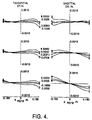
- FIG. 4 is a schematic view of H-tanU curves of an optical system like that of FIGS. 1 and 2 without the diffractive optical element for chromatic aberration correction.
- FIG. 5 is a diagrammatic side elevation view of a second embodiment of the present invention.
- the optical system includes an objective group 12 and a relay group 14 focusing the radiation beam of an object being viewed onto an image plane 16. Generally the radiation enters an entrance pupil 18 and exits an exit pupil 20, which is positioned between the relay group 14 and image plane 16.
- the objective group 12 generally includes a primary mirror 22, a secondary mirror 24 and a fold mirror 26.
- the primary mirror 22 includes a central axis which defines the system optical axis 28.
- the primary mirror 22 is a positive power mirror and may be a conic or higher order aspheric mirror.
- the primary mirror 22 forms an intermediate image of the object being viewed.
- the secondary mirror 24 is a positive power mirror and is positioned on axis with respect to the optical axis 28.
- the secondary mirror is a conic or higher order aspheric mirror.
- the fold mirror 26 is a planar mirror.
- the fold mirror is positioned in the optical path of the beam 30 to fold the beam to make the system more compact.
- the relay group 14 includes a refractive optical element 32 and a diffractive optical element 34.
- the refractive and diffractive optical elements are a hybrid optical element, thus, a single element includes both a refractive and diffractive optical element.
- the refractive and diffractive optical elements are tilted 8.667 degrees and decentered 1.2077 inches with respect to the optical axis 28.
- the hybrid optical element can be positioned on axis with respect to the optical axis.
- the radiant beam 30 is received and reflected from the secondary mirror 24 and projected to the refractive and diffractive elements 32 and 34. As the beam passes through the refractive 32 and diffractive 34 elements, the intermediate image is re-imaged and passed to the image plane 16.
- the field curvature introduced by the primary 22 and secondary 24 mirrors is balanced by the refractive optical element.
- the refractive and diffractive optical elements both have a positive optical power. Thus, the positive optical power of all the optical elements provides for field curvature correction, reducing the overall size of the unit and also reducing the complexity of the system.
- FIG. 3 is the H-tanU curves of the optical system shown in FIG. 1.
- H-tanU curves have been used by skilled optical designers to describe the geometric aberration of an optical system. Those curves in the left and right hand sides correspond to the tangential and sagittal geometric aberrations, respectively.
- the top, middle and bottom curves are the geometric aberrations at full field, 70% field and on-axis, respectively.
- the curves 1, 2 and 3 in each H-tanU plot are the geometric aberrations for the wavelengths of 3.8 ⁇ m, 3.6 ⁇ m and 4.2 ⁇ m, respectively. The wider the spread among the three colors, the worse the chromatic aberration.
- the H-tanU curves in FIG. 3 show practically no chromatic aberration.
- FIG. 4 is the H-tanU curves of a similar optical system except a diffractive optical element is not used on element 32 to correct the chromatic aberration.
- FIG. 4 shows a significant amount of chromatic aberration.
- FIG. 5 another embodiment of the present invention is shown.
- the primary and secondary mirrors 22 and 24 are like those previously described. However, the fold mirror has been eliminated. Thus, the beam 30 is reflected directly from the primary mirror 22 to the secondary mirror 24. Also, an intermediate image is formed between the primary and secondary mirrors.
- the refractive optical element group 50 and refractive-diffractive hybrid optical element 52 are different. Generally, this arrangement of refractive and hybrid optical elements is utilized for visible spectral band wavelengths.
- the refractive optical element 50 includes a group of four refractive lenses.
- the lens group generally includes at least two different types of nominal glass materials, crown glass and flint glass.
- the lenses with positive optical power are crown glass, and the lenses with negative optical power are generally flint glass.
- the primary axial chromatic aberration introduced by the positive optical power lenses is balanced out by the combination of the negative flint glass and the diffractive optical element.
- the secondary axial chromatic aberration is corrected by balancing the optical power between the flint glass optical elements and the diffractive optical element. Since the primary axial and secondary axial chromatic aberrations are very well corrected, the stop shift introduced primarily lateral and secondary lateral chromatic aberrations are very small.
- the refractive optical element illustrated includes lens 54, lens 56, lens 58 and lens 60.
- Lens 54 defines an optical axis which runs through the vertex of the lens.
- lens 54 is a concave-convex lens formed from a crown glass material.
- Lens 54 has a predetermined radius of curvature on the concave or front surface of the lens and a predetermined radius of curvature on the convex or back surface of the lens.
- lens 54 has a predetermined thickness at the vertex and predetermined aperture size on the concave front surface and the convex back surface.
- Lens 56 is centered with respect to the optical axis.
- this lens is a convex-concave lens formed from flint glass material.
- the lens 56 has a predetermined rate of curvature on the convex or front surface of the lens and a predetermined radius of curvature on the concave or back surface of the lens.
- the lens 56 has a predetermined thickness at its vertex and predetermined aperture sizes on the convex front and concave back surfaces.
- the lens 58 is centered with respect to the optical axis.
- the lens 58 is a biconvex lens formed from crown glass material.
- the lens 58 has a predetermined radius of curvature on the convex or front surface of the lens and a predetermined radius of curvature on the convex or back surface of the lens.
- the lens 58 has a predetermined thickness at its vertex and predetermined aperture sizes on the convex front and convex back surfaces.
- the lens 56 and lens 58 are adhered together by conventional means to form a doublet.
- the lens 60 is centered with respect to the optical axis.
- the lens 60 is a concave-convex lens formed from crown glass material.
- the lens 60 has a predetermined radius of curvature on the concave or front surface of the lens and a predetermined rate of curvature on the convex or back surface of the lens.
- the lens 60 has a predetermined thickness at the vertex and a predetermined aperture size on the concave front surface and the convex back surface.
- the hybrid optical element 52 is centered with respect to the optical axis.
- the hybrid optical element 52 consists of a refractive optical element 62 and a diffractive optical element 72.
- the refractive optical element 62 is a convex-planar lens.
- the refractive optical element 62 has a predetermined radius of curvature on the convex or front surface.
- the refractive optical element 62 has a predetermined thickness at its vertex and predetermined aperture sizes on the convex front and planar back surfaces.
- the diffractive optical element 72 is a zone plate pattern with the centers of the rings generally coinciding with the optical axis of the refractive optical element.
- the diffractive optical element, the zone plate pattern is imprinted on the second surface of the refractive optical element 62.
- the second surface of the refractive optical element 62 can be either concave, convex or flat, a flat surface is generally preferred to simplify the fabrication processes of the diffractive optical element.
- the exit pupil 20 is positioned between the secondary mirror 24 and the relay group 14.
- a specific prescription for a re-imaging optical system of FIG. 5 is given in the following table. TABLE 2. Element Radius (inches) CC Decenter (inches) Tilt (degrees) Thickness (inches) Primary Mirror -12.200 -1.000 0.75 7.500 Secondary Mirror 2.800 -1.000 0.75 4.900 Element Glass Type Radius of Curvature Front/Back Distance/Thickness Aperture Diameter Front/Back Lens 54 BAK1 -0.667326/-0.799550 0.250/0.036 0.8/0.96 Lens 56 SF56 4.17351/1.32472 0.120/0.00 1.0/1.0 Lens 58 LAK9 1.32471/-2.76912 0.380/0.066 1.0/1.0 Lens 60 LAKN7 -1.90347/-2.68732 0.320/0.0196 1.0/1.0 Lens 62 LAKN7 1.69427/ ⁇ 0.394/0.00 1.0/1.0 Diffractive Element ⁇ ( ⁇ )
Landscapes
- Physics & Mathematics (AREA)
- General Physics & Mathematics (AREA)
- Optics & Photonics (AREA)
- Geometry (AREA)
- Lenses (AREA)
Claims (11)
- Système optique de reconstitution d'image comprenant :un groupe (12) objectif comprenant un miroir primaire (22) et un miroir secondaire (24), ledit miroir primaire recevant et projetant un faisceau de rayonnement d'un objet observé, ledit miroir secondaire étant positionné de façon à recevoir et réfléchir ledit faisceau de rayonnement provenant dudit miroir primaire, ledit miroir primaire formant une image intermédiaire dudit objet observé, caractérisé parun groupe (14) relais comportant un élément (32) optique de réfraction et un élément (34) optique de diffraction positionné de façon à recevoir ledit faisceau de rayonnement dudit miroir secondaire pour reconstituer ladite image intermédiaire sur un plan (16) image.
- Système selon la revendication 1, dans lequel un miroir (26) de repliement est positionné entre lesdits miroirs primaire et secondaire pour relayer ledit faisceau de rayonnement vers ledit miroir secondaire.
- Système selon l'une quelconque des revendications précédentes, dans lequel lesdits miroirs sont des miroirs à puissance positive.
- Système selon l'une quelconque des revendications précédentes, dans lequel lesdits éléments optiques de réfraction et de diffraction ont une puissance optique positive.
- Système selon l'une quelconque des revendications précédentes, dans lequel lesdits éléments optiques de réfraction et de diffraction sont un élément optique hybride unique.
- Système selon l'une quelconque des revendications précédentes, dans lequel ledit élément optique de réfraction comporte un ensemble de lentilles (54, 56, 58, 60).
- Système selon la revendication 6, dans lequel ledit ensemble de lentilles comprend des lentilles à puissances positives et négatives, la puissance globale dudit ensemble de lentilles étant positive.
- Système selon l'une quelconque des revendications précédentes, dans lequel une pupille (20) de sortie est positionnée entre ledit plan de formation d'image et ledit élément optique de diffraction.
- Système selon la revendication 7, dans lequel une pupille de sortie est positionnée entre ledit miroir secondaire et ledit ensemble de lentilles de réfraction.
- Système selon l'une quelconque des revendications précédentes, dans lequel la combinaison d'un groupe de lentilles de crown-flint et d'un élément optique hybride de réfraction-diffraction corrige les aberrations chromatiques axiales primaire et secondaire.
- Système selon l'une quelconque des revendications précédentes, dans lequel la combinaison d'un groupe de lentilles de crown-flint et d'un élément optique hybride de réfraction-diffraction corrige les aberrations chromatiques latérales primaire et secondaire.
Applications Claiming Priority (2)
| Application Number | Priority Date | Filing Date | Title |
|---|---|---|---|
| US864858 | 1992-04-07 | ||
| US07/864,858 US5287218A (en) | 1992-04-07 | 1992-04-07 | Re-imaging optical system including refractive and diffractive optical elements |
Publications (3)
| Publication Number | Publication Date |
|---|---|
| EP0565355A2 EP0565355A2 (fr) | 1993-10-13 |
| EP0565355A3 EP0565355A3 (en) | 1993-12-08 |
| EP0565355B1 true EP0565355B1 (fr) | 1997-10-01 |
Family
ID=25344233
Family Applications (1)
| Application Number | Title | Priority Date | Filing Date |
|---|---|---|---|
| EP93302722A Expired - Lifetime EP0565355B1 (fr) | 1992-04-07 | 1993-04-07 | Système optique à relais d'image |
Country Status (6)
| Country | Link |
|---|---|
| US (1) | US5287218A (fr) |
| EP (1) | EP0565355B1 (fr) |
| JP (1) | JPH0627382A (fr) |
| DE (1) | DE69314215T2 (fr) |
| ES (1) | ES2107621T3 (fr) |
| IL (1) | IL105334A (fr) |
Families Citing this family (39)
| Publication number | Priority date | Publication date | Assignee | Title |
|---|---|---|---|---|
| JP3212203B2 (ja) * | 1993-02-09 | 2001-09-25 | オリンパス光学工業株式会社 | 視覚表示装置 |
| US5363235A (en) * | 1993-02-10 | 1994-11-08 | Hughes Aircraft Company | Dual field of view multi wavelength sensor |
| JP2786796B2 (ja) * | 1993-06-23 | 1998-08-13 | シャープ株式会社 | プロジェクター |
| US5410434A (en) * | 1993-09-09 | 1995-04-25 | Ultratech Stepper, Inc. | Reflective projection system comprising four spherical mirrors |
| JP3063485B2 (ja) * | 1993-09-10 | 2000-07-12 | キヤノン株式会社 | 反射光学系 |
| JPH07128590A (ja) * | 1993-10-29 | 1995-05-19 | Olympus Optical Co Ltd | 縮小投影レンズ |
| US5543966A (en) * | 1993-12-29 | 1996-08-06 | Eastman Kodak Company | Hybrid refractive/diffractive achromatic camera lens |
| US5581405A (en) * | 1993-12-29 | 1996-12-03 | Eastman Kodak Company | Hybrid refractive/diffractive achromatic camera lens and camera using such |
| IL113789A (en) * | 1994-05-23 | 1999-01-26 | Hughes Aircraft Co | A non-focusing device with three hinged mirrors and a corrective mirror |
| US5623473A (en) * | 1994-06-30 | 1997-04-22 | Nikon Corporation | Method and apparatus for manufacturing a diffraction grating zone plate |
| US5774569A (en) * | 1994-07-25 | 1998-06-30 | Waldenmaier; H. Eugene W. | Surveillance system |
| US5446588A (en) * | 1994-07-29 | 1995-08-29 | The University Of Rochester | Wide-angle eyepiece optical system employing refractive and diffractive optical elements |
| US5691847A (en) * | 1994-08-08 | 1997-11-25 | Hughes Aircraft Company | Athermalized and achromatized optical systems employing diffractive optical element |
| IL113350A (en) * | 1995-04-12 | 1998-06-15 | State Rafaelel Ministry Of Def | Catadioptric optics working staring detector system |
| JPH08286113A (ja) * | 1995-04-17 | 1996-11-01 | Olympus Optical Co Ltd | 対物レンズ |
| NL1001952C2 (nl) * | 1995-12-21 | 1997-06-24 | Tno | Telescoop met groot gezichtsveld. |
| US6157498A (en) | 1996-06-19 | 2000-12-05 | Nikon Corporation | Dual-imaging optical system |
| GB9711366D0 (en) * | 1997-06-02 | 1997-07-30 | Pilkington Perkin Elmer Ltd | Optical imaging system |
| US5880879A (en) * | 1997-08-26 | 1999-03-09 | Nikon Corporation | Objective lens system utilizing diffractive optical element |
| JP4717974B2 (ja) * | 1999-07-13 | 2011-07-06 | 株式会社ニコン | 反射屈折光学系及び該光学系を備える投影露光装置 |
| US6342967B1 (en) * | 2000-02-25 | 2002-01-29 | Janusz S. Wilczynski | Photolithography lens |
| JP2001343589A (ja) * | 2000-03-31 | 2001-12-14 | Canon Inc | 投影光学系、および該投影光学系による投影露光装置、デバイス製造方法 |
| JP2002156580A (ja) * | 2000-09-05 | 2002-05-31 | Canon Inc | 結像素子及び画像読取装置 |
| FR2818757B1 (fr) * | 2000-12-22 | 2003-03-21 | Cit Alcatel | Architecture optique de telescope d'observation et en particulier pour observation de la terre a partir d'un satellite |
| RU2215314C2 (ru) * | 2001-10-29 | 2003-10-27 | Институт солнечно-земной физики СО РАН | Широкоугольный зеркальный объектив телескопа |
| US6950241B1 (en) | 2002-09-18 | 2005-09-27 | Dmetrix, Inc. | Miniature microscope objective for an array microscope |
| US20050013021A1 (en) * | 2003-06-10 | 2005-01-20 | Olympus Corporation | Decentered optical system, light transmitting device, light receiving device, and optical system |
| US7390101B2 (en) * | 2005-01-31 | 2008-06-24 | The Boeing Company | Off-axis two-mirror re-imaging infrared telescope |
| US20060198018A1 (en) * | 2005-02-04 | 2006-09-07 | Carl Zeiss Smt Ag | Imaging system |
| JP2011033737A (ja) * | 2009-07-30 | 2011-02-17 | Fujifilm Corp | 投写光学系およびこれを用いた投写型表示装置 |
| US8947778B2 (en) * | 2010-06-01 | 2015-02-03 | Richard F. Horton | Two mirror unobscured telescopes with tilted focal surfaces |
| US9007497B2 (en) * | 2010-08-11 | 2015-04-14 | Media Lario S.R.L. | Three-mirror anastigmat with at least one non-rotationally symmetric mirror |
| US9766422B1 (en) | 2013-12-20 | 2017-09-19 | Ball Aerospace & Technologies Corp. | Optical membrane heating and temperature control method and apparatus |
| US9535258B1 (en) * | 2013-12-30 | 2017-01-03 | Ball Aerospace & Technologies Corp. | Method and apparatus for correcting chromatic aberrations in a telescope |
| US9709793B1 (en) | 2013-12-31 | 2017-07-18 | Ball Aerospace & Technologies Corp. | Deployable structure |
| CN108345095B (zh) * | 2018-03-30 | 2024-07-30 | 中国科学院西安光学精密机械研究所 | 一种宽幅低杂光全天时星跟踪器光学结构 |
| JP7223248B2 (ja) * | 2018-11-01 | 2023-02-16 | セイコーエプソン株式会社 | 表示装置 |
| CN111999848B (zh) * | 2020-08-04 | 2022-07-29 | 北京空间机电研究所 | 一种离轴三反多光谱空间遥感相机双成像通道光学镜头 |
| JP7037846B1 (ja) * | 2021-04-26 | 2022-03-17 | 合同会社北海道環境・エネルギー研究所 | 主鏡と位置をオフセットさせた副鏡とを有するオフセット光学システム |
Family Cites Families (21)
| Publication number | Priority date | Publication date | Assignee | Title |
|---|---|---|---|---|
| GB476147A (en) * | 1936-04-01 | 1937-12-02 | Heinrich Wild | Improvements in telescopes |
| DE1293468B (de) * | 1966-09-08 | 1969-04-24 | Leitz Ernst Gmbh | Katadioptrisches System fuer photographische Zwecke |
| CH542454A (de) * | 1971-08-18 | 1973-09-30 | Kern & Co Ag | Lichtstarkes katadioptrisches Objektiv |
| US3897133A (en) * | 1973-03-05 | 1975-07-29 | David A Warner | Telescopic optical system |
| US4265510A (en) * | 1979-05-16 | 1981-05-05 | Hughes Aircraft Company | Three mirror anastigmatic optical system |
| US4431917A (en) * | 1981-11-27 | 1984-02-14 | Texas Instruments Incorporated | Compact, high cold shield efficiency optical system |
| US4523816A (en) * | 1983-08-12 | 1985-06-18 | Vivitar Corporation | Catadioptric lens |
| JPS61156737A (ja) * | 1984-12-27 | 1986-07-16 | Canon Inc | 回路の製造方法及び露光装置 |
| US4737021A (en) * | 1986-03-21 | 1988-04-12 | Dietrich Korsch | Wide-field three-mirror collimator |
| US4757354A (en) * | 1986-05-02 | 1988-07-12 | Matsushita Electrical Industrial Co., Ltd. | Projection optical system |
| US4804258A (en) * | 1986-05-05 | 1989-02-14 | Hughes Aircraft Company | Four mirror afocal wide field of view optical system |
| US4834517A (en) * | 1987-01-13 | 1989-05-30 | Hughes Aircraft Company | Method and apparatus for receiving optical signals |
| US4895790A (en) * | 1987-09-21 | 1990-01-23 | Massachusetts Institute Of Technology | High-efficiency, multilevel, diffractive optical elements |
| US4964706A (en) * | 1988-10-17 | 1990-10-23 | Hughes Aircraft Company | Multi-focal length, multi-field of view three mirror anastrigmat |
| US4993818A (en) * | 1988-10-17 | 1991-02-19 | Hughes Aircraft Company | Continuous zoom all-reflective optical system |
| US5044706A (en) * | 1990-02-06 | 1991-09-03 | Hughes Aircraft Company | Optical element employing aspherical and binary grating optical surfaces |
| WO1991012551A1 (fr) * | 1990-02-14 | 1991-08-22 | Massachusetts Institute Of Technology | Combinaison lentille/plaque de zone pour correction de la dispersion chromatique |
| JP2701512B2 (ja) * | 1990-03-15 | 1998-01-21 | キヤノン株式会社 | 反射系を有した撮像装置 |
| JPH0416910A (ja) * | 1990-05-11 | 1992-01-21 | Omron Corp | 光学レンズ |
| US5009494A (en) * | 1990-05-21 | 1991-04-23 | Hughes Aircraft Company | Wide field all-reflective multiple field of view telescope |
| US5153772A (en) * | 1991-04-09 | 1992-10-06 | Toledyne Industries, Inc. | Binary optic-corrected multistage imaging system |
-
1992
- 1992-04-07 US US07/864,858 patent/US5287218A/en not_active Expired - Fee Related
-
1993
- 1993-04-07 JP JP5080965A patent/JPH0627382A/ja active Pending
- 1993-04-07 DE DE69314215T patent/DE69314215T2/de not_active Expired - Fee Related
- 1993-04-07 EP EP93302722A patent/EP0565355B1/fr not_active Expired - Lifetime
- 1993-04-07 IL IL10533493A patent/IL105334A/en not_active IP Right Cessation
- 1993-04-07 ES ES93302722T patent/ES2107621T3/es not_active Expired - Lifetime
Also Published As
| Publication number | Publication date |
|---|---|
| IL105334A0 (en) | 1993-09-22 |
| DE69314215D1 (de) | 1997-11-06 |
| US5287218A (en) | 1994-02-15 |
| DE69314215T2 (de) | 1998-01-29 |
| ES2107621T3 (es) | 1997-12-01 |
| JPH0627382A (ja) | 1994-02-04 |
| EP0565355A3 (en) | 1993-12-08 |
| EP0565355A2 (fr) | 1993-10-13 |
| IL105334A (en) | 1996-05-14 |
Similar Documents
| Publication | Publication Date | Title |
|---|---|---|
| US5287218A (en) | Re-imaging optical system including refractive and diffractive optical elements | |
| EP0689075B1 (fr) | Système d'imagerie avec image intermédiaire d'un système anastigmatique à trois mirroirs et un miroir correcteur | |
| US6016220A (en) | Off-axis three-mirror anastigmat having corrector mirror | |
| EP0532267B1 (fr) | Système optique à relais d'image utilisant des éléments optiques de réfraction et diffraction | |
| US5731899A (en) | Lenslet array system incorporating an integral field lens/reimager lenslet array | |
| US5822125A (en) | Lenslet array system | |
| EP0566001B1 (fr) | Système optique d'affichage d'image virtuelle à large bande spectrale | |
| EP0299011B1 (fr) | Procede et appareil de reception de signaux optiques | |
| EP0095622B1 (fr) | Système optique | |
| US5031976A (en) | Catadioptric imaging system | |
| US5471346A (en) | Casegrain telescope with spherical mirror surfaces | |
| US8427744B2 (en) | All-reflective relayed focal telescope derived from the first two mirrors of an afocal three-mirror anastigmat | |
| US5140459A (en) | Apparatus and method for optical relay and reimaging | |
| US20040246595A1 (en) | Optical imaging system with aberration correcting means | |
| WO1992010774A1 (fr) | Elements optiques a gradient d'indice et systemes optiques catadioptriques | |
| US5812322A (en) | Lenslet array system incorporating a field lenslet array | |
| EP0045138A1 (fr) | Système optique infrarouge | |
| GB2030315A (en) | Catadioptric Infra-red Lenses | |
| GB2491976A (en) | Adaptation optical lens unit for upstream chromatic aberration correction | |
| GB2136149A (en) | High Magnification Afocal Infrared Telescopes | |
| US6118578A (en) | Simplified dual field of view afocal | |
| Seppala | Improved optical design for the large synoptic survey telescope (lsst) | |
| CN217504983U (zh) | 一种成像光谱仪分光系统 | |
| WO1995034013A1 (fr) | Systeme optique grande vitesse | |
| US3305293A (en) | Catadioptric optical system |
Legal Events
| Date | Code | Title | Description |
|---|---|---|---|
| PUAI | Public reference made under article 153(3) epc to a published international application that has entered the european phase |
Free format text: ORIGINAL CODE: 0009012 |
|
| AK | Designated contracting states |
Kind code of ref document: A2 Designated state(s): CH DE ES FR GB LI SE |
|
| PUAL | Search report despatched |
Free format text: ORIGINAL CODE: 0009013 |
|
| AK | Designated contracting states |
Kind code of ref document: A3 Designated state(s): CH DE ES FR GB LI SE |
|
| 17P | Request for examination filed |
Effective date: 19940512 |
|
| 17Q | First examination report despatched |
Effective date: 19960814 |
|
| GRAG | Despatch of communication of intention to grant |
Free format text: ORIGINAL CODE: EPIDOS AGRA |
|
| GRAH | Despatch of communication of intention to grant a patent |
Free format text: ORIGINAL CODE: EPIDOS IGRA |
|
| GRAH | Despatch of communication of intention to grant a patent |
Free format text: ORIGINAL CODE: EPIDOS IGRA |
|
| GRAA | (expected) grant |
Free format text: ORIGINAL CODE: 0009210 |
|
| AK | Designated contracting states |
Kind code of ref document: B1 Designated state(s): CH DE ES FR GB LI SE |
|
| PG25 | Lapsed in a contracting state [announced via postgrant information from national office to epo] |
Ref country code: FR Free format text: THE PATENT HAS BEEN ANNULLED BY A DECISION OF A NATIONAL AUTHORITY Effective date: 19971001 |
|
| REG | Reference to a national code |
Ref country code: CH Ref legal event code: NV Representative=s name: ISLER & PEDRAZZINI AG Ref country code: CH Ref legal event code: EP |
|
| REF | Corresponds to: |
Ref document number: 69314215 Country of ref document: DE Date of ref document: 19971106 |
|
| REG | Reference to a national code |
Ref country code: ES Ref legal event code: FG2A Ref document number: 2107621 Country of ref document: ES Kind code of ref document: T3 |
|
| ET | Fr: translation filed | ||
| PG25 | Lapsed in a contracting state [announced via postgrant information from national office to epo] |
Ref country code: GB Free format text: LAPSE BECAUSE OF NON-PAYMENT OF DUE FEES Effective date: 19980407 |
|
| PG25 | Lapsed in a contracting state [announced via postgrant information from national office to epo] |
Ref country code: SE Free format text: LAPSE BECAUSE OF NON-PAYMENT OF DUE FEES Effective date: 19980408 Ref country code: ES Free format text: LAPSE BECAUSE OF NON-PAYMENT OF DUE FEES Effective date: 19980408 |
|
| PG25 | Lapsed in a contracting state [announced via postgrant information from national office to epo] |
Ref country code: LI Free format text: LAPSE BECAUSE OF NON-PAYMENT OF DUE FEES Effective date: 19980430 Ref country code: CH Free format text: LAPSE BECAUSE OF NON-PAYMENT OF DUE FEES Effective date: 19980430 |
|
| PLBE | No opposition filed within time limit |
Free format text: ORIGINAL CODE: 0009261 |
|
| STAA | Information on the status of an ep patent application or granted ep patent |
Free format text: STATUS: NO OPPOSITION FILED WITHIN TIME LIMIT |
|
| 26N | No opposition filed | ||
| GBPC | Gb: european patent ceased through non-payment of renewal fee |
Effective date: 19980407 |
|
| REG | Reference to a national code |
Ref country code: CH Ref legal event code: PL |
|
| EUG | Se: european patent has lapsed |
Ref document number: 93302722.9 |
|
| PG25 | Lapsed in a contracting state [announced via postgrant information from national office to epo] |
Ref country code: DE Free format text: LAPSE BECAUSE OF NON-PAYMENT OF DUE FEES Effective date: 19990202 |
|
| REG | Reference to a national code |
Ref country code: FR Ref legal event code: ST |
|
| REG | Reference to a national code |
Ref country code: ES Ref legal event code: FD2A Effective date: 20030203 |