EP0565372A2 - Raccords de tuyaux - Google Patents
Raccords de tuyaux Download PDFInfo
- Publication number
- EP0565372A2 EP0565372A2 EP93302762A EP93302762A EP0565372A2 EP 0565372 A2 EP0565372 A2 EP 0565372A2 EP 93302762 A EP93302762 A EP 93302762A EP 93302762 A EP93302762 A EP 93302762A EP 0565372 A2 EP0565372 A2 EP 0565372A2
- Authority
- EP
- European Patent Office
- Prior art keywords
- ring
- gland
- spigot
- pipe
- gland ring
- Prior art date
- Legal status (The legal status is an assumption and is not a legal conclusion. Google has not performed a legal analysis and makes no representation as to the accuracy of the status listed.)
- Granted
Links
Images


Classifications
-
- F—MECHANICAL ENGINEERING; LIGHTING; HEATING; WEAPONS; BLASTING
- F16—ENGINEERING ELEMENTS AND UNITS; GENERAL MEASURES FOR PRODUCING AND MAINTAINING EFFECTIVE FUNCTIONING OF MACHINES OR INSTALLATIONS; THERMAL INSULATION IN GENERAL
- F16L—PIPES; JOINTS OR FITTINGS FOR PIPES; SUPPORTS FOR PIPES, CABLES OR PROTECTIVE TUBING; MEANS FOR THERMAL INSULATION IN GENERAL
- F16L21/00—Joints with sleeve or socket
- F16L21/08—Joints with sleeve or socket with additional locking means
-
- Y—GENERAL TAGGING OF NEW TECHNOLOGICAL DEVELOPMENTS; GENERAL TAGGING OF CROSS-SECTIONAL TECHNOLOGIES SPANNING OVER SEVERAL SECTIONS OF THE IPC; TECHNICAL SUBJECTS COVERED BY FORMER USPC CROSS-REFERENCE ART COLLECTIONS [XRACs] AND DIGESTS
- Y10—TECHNICAL SUBJECTS COVERED BY FORMER USPC
- Y10S—TECHNICAL SUBJECTS COVERED BY FORMER USPC CROSS-REFERENCE ART COLLECTIONS [XRACs] AND DIGESTS
- Y10S285/00—Pipe joints or couplings
- Y10S285/906—Equivalents
Definitions
- This invention relates to pipe couplings of the type in which a metal fitting is sealingly secured on an end of a plain length of "rigid" plastics pipe, e.g., polyethylene.
- An object of the present invention is to provide such a metal fitting which when secured on a pipe withstands test pressures and is "fully end load restrained", i.e., the pipe should break before it can pull out of the fitting.
- Another object is to provide such a metal fitting which is readily fitted on site without requiring special tooling or associated equipment.
- a further object is to provide such a metal fitting with means for indicating that the fitting has been properly positioned on a pipe.
- Yet another object is to provide such a metal fitting with means for indicating that the fitting has been satisfactorily fitted on a pipe.
- a metal fitting for an end of a plain length of pipe comprises a body with flange means adjacent a first end, a gland ring adjacent the other end of the body, a grip ring between the body and the gland ring, and screw fasteners for urging the gland ring towards the flange means; characterised in that:-
- the body has an integral outer tubular spigot projecting towards the gland ring and a co-axial integral inner tubular spigot having a cylindrical outer surface projecting beyond the free end of the outer tub- ularspigot, the inside of the outer spigot being provided with a frustoconical portion adjacent and converging from that free end;
- the gland ring has its inside provided with a similar frustoconical portion converging in the opposite direction;
- the grip ring is a split ring having external surfaces mating with the frustoconical portions in the body and the gland ring, and internal circumferentially disposed ribs initially spaced radially from the cylindrical outer surface of the inner spigot by no less than the thickness of a plain length of pipe on one end of which the metal fitting is intended to be fitted.
- the screw fasteners are tightened to urge the gland ring towards the flange means, whereby the wedging action of the external surfaces on the grip ring within the frustoconical portions inside the outer spigot and the gland ring causes the grip ring to be urged radially inwards and its internal ribs to dig into the pipe, thus securing the metal fitting on the pipe and effecting sealing between the inside of the pipe and the outside of the inner spigot.
- the outer spigot of the body preferably has a notch extending from its free end to beyond the adjacent edge of the grip ring, to enable the end proper of an inserted pipe to be brought into view to indicate proper positioning of the metal fitting on the pipe before tightening of the screw fasteners.
- the frustoconical portions inside the outer spigot of the body and the gland ring, and the mating external surfaces on the grip ring, may have a cone angle in the range of 10° to 20°, preferably 15° to facilitate on site tightening of the screw fasteners by a wrench or spanner without undue effort or leverage; which screw fasteners are conveniently bolts through holes in the flange means and the gland ring, with bolt heads in matching recesses in the flange means or in the gland ring and with nuts and washers abutting the gland ring or the flange means, as the case may be.
- the internal circumferentially disposed ribs of the grip ring are preferably generally semicircular in axial cross-section and spaced apart by cylindrical portions of the inside of the ring; the rib at the gland ring end of the grip ring is preferably spaced from the adjacent end proper of the grip ring by a cylindrical portion of the inside of the grip ring, so that, after tightening of the screw fasteners by the requisite amount, the gap between the outside of an inserted pipe and that end proper of the grip ring will be fully closed, thus indicating full penetration of the ribs into the pipe; conveniently, the rib at the other end of the grip ring is similarly spaced from the adjacent end proper, so that the grip ring can be inserted either way round in the fitting.
- the external surfaces on the grip ring, mating with the frustoconical portions inside the outer spigot and the gland ring, may be provided on axially disposed ribs, whereby the portions of reduced thickness of the grip ring between the axially disposed ribs ensure adequate flexibility in the grip ring, butforlarg- er pipe diameters, e.g., above 90 mm the external surfaces of the grip ring are preferably substantially complete surfaces of revolution, i.e., non-ribbed.
- the flange means may be a flange integral with the first end of the body and the holes in the flange may be circumferentially spaced intermediate holes for bolts for securing the flange to anotherflanged fitting; and the flange may extend radially from a spigot or socket for mating with a socket or spigot, as the case may be, on another similarly flanged fitting.
- the flange means may be the gland ring of a compression seal having an elastomeric sealing ring in a socket in the first end of the body, e.g., for sealing on to a plain pipe end of e.g., cast iron, steel, UPVC or asbestoscement, in which case the screw fasteners may extend from one gland ring to the other.
- the flange means may be another gland ring adjacent the first end of the body and similar to the gland ring at the other end of the body, together with similar outer and inner tubular spigots integral with the first end of the body, and a similar grip ring, i.e., for securing and sealing on another plain pipe end, e.g., of "rigid" plastics, in which case the screw fasteners may extend from one gland ring to the other.
- An alternative to screw fasteners extending from one gland ring to the other comprises an intermediate flange integral with the body (or a pair of intermediate integral flanges) to which the screw fasteners extend from the gland rings.
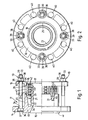
- a metal fitting 11 for an end of a plain length of plastics pipe 12 (see Figures 3 and 4) comprises a body 13 with flange means 14 adjacent a first end 15, a gland ring 16 adjacent the other end 17 of the body, a grip ring 18 between the body 13 and the gland ring 16, and screw fasteners 19 for urging the gland ring 16 towards the flange means 14; characterised in that:-
- the body 13 has an integral outer tubular spigot 20 projecting towards the gland ring 16 and a co-axial integral inner tubular spigot 21 having a cylindrical outer surface 22 projecting beyond the free end 23 of the outer tubular spigot 20, the inside 24 of the outer spigot being provided with a frustoconical portion 25 adjacent and converging from that free end;
- the gland ring 16 has its inside provided with a similar frustoconical portion 26 converging in the opposite direction;
- the grip ring 18 is a split ring having external surfaces 27, 28 mating with the frustoconical portions 25, 26 in the body 13 and the gland ring 16, and internal circumferentially disposed ribs 29 initially spaced radially from the cylindrical outer surface 22 of the inner spigot 21 by no less than the thickness T of the plain length of plastics pipe 12 on one end of which the metal fitting 11 is intended to be fitted.
- the outer spigot 20 has a notch 30 extending from its free end 23 to beyond the adjacent edge 31 of the grip ring 18, to enable the end 32 proper of the inserted pipe 12 to be brought into view (see Figure 3) to indicate proper positioning of the metal fitting on the plastics pipe before tightening of the screw fasteners 19.
- the frustoconical portions 25, 26 have a cone angle of 15° to facilitate on site tightening of the screw fasteners 19 by a wrench or spanner without undue effort or leverage.
- the screw fasteners 19 are bolts 33 through holes 34, 35 in the flange means 14 and the gland ring 16, with bolt heads 36 in matching recesses 37 in the flange means and with nuts 38 and washers 39 abutting the gland ring.
- the flange means 14 is a flange integral with the first end 15 of the body 13 and the holes 34 in the flange are circumferentially spaced intermediate holes 40 (see Figure 2) for bolts (not shown) for securing the flange 14 to another flanged fitting (not shown).
- the flange 14 extends radially from a spigot 41 for mating with a socket in another similarly flanged fitting.
- the internal circumferentially disposed ribs 29 of the grip ring 18 are generally semicircular in axial cross-section and spaced apart by cylindrical portions 42 of the inside of the ring; the end ribs are spaced from the adjacent ends proper of the grip ring so that it can be inserted either way round in the fitting 11 and after tightening of the screw fasteners 19 by the requisite amount, the gap between the outside of the inserted pipe 12 and the end of grip ring adjacent the gland ring 16 will be fully closed (see Figure 4), thus indicating full penetration of the ribs 29 into the pipe.
- the external surfaces 27, 28 on the grip ring 18 are provided on axially disposed ribs 43 (see also Figures 7 and 8), whereby the portions of reduced thickness of the grip ring between the axially disposed ribs ensure adequate flexibility in the grip ring, butforlarg- er pipe diameters, e.g. above 90 mm, the external surfaces of the grip ring may bew substantially complete surfaces of revolution, i.e., non-ribbed, such as shown as 27X and 28X in Figures 9 and 10.
- the flange means 14 is the gland ring of a compression seal having an elasomeric sealing ring 44 in a socket 45 in the first end 15 of the body 13, e.g., for sealing on to a plain end pipe (not shown) of e.g., cast iron, steel, UPVC or asbestos-cement, and the bolts 33 of the screw fasteners 19 extend from one gland ring 14 to the other gland ring 16.
- the flange means 14 is another gland ring adjacent the first end 15 of the body 13 and similar to the gland ring 16 at the other end 17 of the body, togetherwith similarouterand innertubularspi- gots 20, 21 integral with the first end of the body, and a similar grip ring 18, i.e., for securing and sealing on another plain pipe end (not shown), and the bolts 33 of the screw fasteners 19 again extend from one gland ring 14 to the other gland ring 16.
Landscapes
- Engineering & Computer Science (AREA)
- General Engineering & Computer Science (AREA)
- Mechanical Engineering (AREA)
- Joints With Sleeves (AREA)
- Mutual Connection Of Rods And Tubes (AREA)
- Joints With Pressure Members (AREA)
Applications Claiming Priority (4)
| Application Number | Priority Date | Filing Date | Title |
|---|---|---|---|
| GB929207924A GB9207924D0 (en) | 1992-04-10 | 1992-04-10 | Flanged pipes |
| GB9207924 | 1992-04-10 | ||
| GB9209547 | 1992-05-01 | ||
| GB929209547A GB9209547D0 (en) | 1992-05-01 | 1992-05-01 | Pipe couplings |
Publications (3)
| Publication Number | Publication Date |
|---|---|
| EP0565372A2 true EP0565372A2 (fr) | 1993-10-13 |
| EP0565372A3 EP0565372A3 (en) | 1994-05-25 |
| EP0565372B1 EP0565372B1 (fr) | 1997-05-28 |
Family
ID=26300686
Family Applications (1)
| Application Number | Title | Priority Date | Filing Date |
|---|---|---|---|
| EP93302762A Expired - Lifetime EP0565372B1 (fr) | 1992-04-10 | 1993-04-07 | Raccords de tuyaux |
Country Status (6)
| Country | Link |
|---|---|
| US (1) | US5360238A (fr) |
| EP (1) | EP0565372B1 (fr) |
| CA (1) | CA2093720C (fr) |
| DE (1) | DE69310988T2 (fr) |
| ES (1) | ES2101948T3 (fr) |
| GB (1) | GB2266130B (fr) |
Cited By (2)
| Publication number | Priority date | Publication date | Assignee | Title |
|---|---|---|---|---|
| DE19525157C1 (de) * | 1995-07-11 | 1997-01-30 | Puspas Armaturen Gmbh | Kupplung für Gas oder Wasser führende Rohre |
| EP0962941A1 (fr) * | 1998-06-08 | 1999-12-08 | General Electric Company | Dispositif et procédé adaptés au raccord d'une tuyauterie d'aspersion du coeur |
Families Citing this family (5)
| Publication number | Priority date | Publication date | Assignee | Title |
|---|---|---|---|---|
| GB2285665A (en) * | 1994-01-18 | 1995-07-19 | Belgicast S A | Pipe coupling for polyethlene pipes |
| DE10000008A1 (de) | 2000-01-03 | 2001-07-12 | Alcatel Sa | Verfahren zur aufwandsarmen Signal-, Ton- und Phasenwechseldetektion |
| AU2005337422B2 (en) * | 2005-10-12 | 2010-09-30 | Philmac Pty Ltd | A pipe coupling adapted for sealing the end of a pipe |
| US8579985B2 (en) | 2006-12-07 | 2013-11-12 | Ihip Surgical, Llc | Method and apparatus for hip replacement |
| US8974540B2 (en) | 2006-12-07 | 2015-03-10 | Ihip Surgical, Llc | Method and apparatus for attachment in a modular hip replacement or fracture fixation device |
Family Cites Families (9)
| Publication number | Priority date | Publication date | Assignee | Title |
|---|---|---|---|---|
| US1622768A (en) * | 1924-06-04 | 1927-03-29 | Cook Henry Denman | Pipe joint and connection |
| US2452278A (en) * | 1945-06-29 | 1948-10-26 | George V Woodling | Tube coupling device |
| US2727761A (en) * | 1951-10-27 | 1955-12-20 | Hughes Tool Co | Couplers for fluid-conducting conduits |
| FR1420487A (fr) * | 1964-10-20 | 1965-12-10 | Lotigie Ets | Raccord à bride pour tubes semi-rigides et rigides cylindriques à bout uni en matières plastiques |
| US3649050A (en) * | 1970-06-15 | 1972-03-14 | George V Woodling | Tube fitting connection |
| US4054305A (en) * | 1976-04-15 | 1977-10-18 | I-T-E Imperial Corporation Efcor Division | Thread making fitting for unthreaded conduit |
| GB2110784A (en) * | 1981-12-02 | 1983-06-22 | Artus Feist | Coupling for the connection of flexible pipes |
| US4575274A (en) * | 1983-03-02 | 1986-03-11 | Gilbert Engineering Company Inc. | Controlled torque connector assembly |
| US4832379A (en) * | 1987-01-28 | 1989-05-23 | The Pipe Line Development Company | Collet grip riser fitting |
-
1993
- 1993-04-07 EP EP93302762A patent/EP0565372B1/fr not_active Expired - Lifetime
- 1993-04-07 DE DE69310988T patent/DE69310988T2/de not_active Expired - Fee Related
- 1993-04-07 GB GB9307313A patent/GB2266130B/en not_active Expired - Fee Related
- 1993-04-07 ES ES93302762T patent/ES2101948T3/es not_active Expired - Lifetime
- 1993-04-08 CA CA002093720A patent/CA2093720C/fr not_active Expired - Fee Related
- 1993-04-09 US US08/045,993 patent/US5360238A/en not_active Expired - Fee Related
Cited By (2)
| Publication number | Priority date | Publication date | Assignee | Title |
|---|---|---|---|---|
| DE19525157C1 (de) * | 1995-07-11 | 1997-01-30 | Puspas Armaturen Gmbh | Kupplung für Gas oder Wasser führende Rohre |
| EP0962941A1 (fr) * | 1998-06-08 | 1999-12-08 | General Electric Company | Dispositif et procédé adaptés au raccord d'une tuyauterie d'aspersion du coeur |
Also Published As
| Publication number | Publication date |
|---|---|
| US5360238A (en) | 1994-11-01 |
| DE69310988D1 (de) | 1997-07-03 |
| CA2093720A1 (fr) | 1993-10-11 |
| GB2266130A (en) | 1993-10-20 |
| GB9307313D0 (en) | 1993-06-02 |
| GB2266130B (en) | 1995-04-19 |
| DE69310988T2 (de) | 1997-09-04 |
| CA2093720C (fr) | 1998-10-27 |
| EP0565372B1 (fr) | 1997-05-28 |
| ES2101948T3 (es) | 1997-07-16 |
| EP0565372A3 (en) | 1994-05-25 |
Similar Documents
| Publication | Publication Date | Title |
|---|---|---|
| US5509699A (en) | Mechanical joint pipe adapter with inserted flexible spline | |
| CA2463004C (fr) | Manchon d'accouplement | |
| US6502867B2 (en) | Flanged pipe fitting | |
| US4779900A (en) | Segmented pipe joint retainer glands | |
| EP1476689B1 (fr) | Dispositif d'ancrage pour raccord | |
| US3141686A (en) | Pipe coupling | |
| US4867488A (en) | Restrained joint with gripper gland | |
| US4050722A (en) | Joint for conduit | |
| WO1995033948A9 (fr) | Adapateur mecanique pour le raccordement de tuyaux | |
| US4896903A (en) | Segmented pipe joint retainer glands | |
| EP1033518B1 (fr) | Raccord de tuyaux | |
| US5505499A (en) | Pipe coupling | |
| US4435005A (en) | Joint for conduit with single threaded end | |
| US7552949B2 (en) | Joint restraint for pipe fittings | |
| US5082313A (en) | Cut-in repair coupling | |
| US6086111A (en) | Pipe coupling | |
| US4005879A (en) | Conduit joint | |
| GB2249599A (en) | End-fittings for pipes with compressible linings | |
| US4576403A (en) | Pressure fitting | |
| US6129391A (en) | Plastic coupling for plastic pipe having a completed installation signal | |
| US5360238A (en) | Pipe couplings | |
| US3984130A (en) | Pipe joint for an intermediate metal conduit | |
| EP0472379B1 (fr) | Raccords pour tuyaux | |
| GB1562797A (en) | Pipe couplings and joints | |
| GB2167146A (en) | Pipe coupling |
Legal Events
| Date | Code | Title | Description |
|---|---|---|---|
| PUAI | Public reference made under article 153(3) epc to a published international application that has entered the european phase |
Free format text: ORIGINAL CODE: 0009012 |
|
| AK | Designated contracting states |
Kind code of ref document: A2 Designated state(s): DE ES FR IE NL |
|
| PUAL | Search report despatched |
Free format text: ORIGINAL CODE: 0009013 |
|
| AK | Designated contracting states |
Kind code of ref document: A3 Designated state(s): DE ES FR IE NL |
|
| 17P | Request for examination filed |
Effective date: 19941110 |
|
| 17Q | First examination report despatched |
Effective date: 19960417 |
|
| GRAG | Despatch of communication of intention to grant |
Free format text: ORIGINAL CODE: EPIDOS AGRA |
|
| GRAH | Despatch of communication of intention to grant a patent |
Free format text: ORIGINAL CODE: EPIDOS IGRA |
|
| GRAH | Despatch of communication of intention to grant a patent |
Free format text: ORIGINAL CODE: EPIDOS IGRA |
|
| GRAA | (expected) grant |
Free format text: ORIGINAL CODE: 0009210 |
|
| RAP1 | Party data changed (applicant data changed or rights of an application transferred) |
Owner name: UNDERPRESSURE ENGINEERING PLC |
|
| AK | Designated contracting states |
Kind code of ref document: B1 Designated state(s): DE ES FR IE NL |
|
| REF | Corresponds to: |
Ref document number: 69310988 Country of ref document: DE Date of ref document: 19970703 |
|
| REG | Reference to a national code |
Ref country code: ES Ref legal event code: FG2A Ref document number: 2101948 Country of ref document: ES Kind code of ref document: T3 |
|
| ET | Fr: translation filed | ||
| PLBE | No opposition filed within time limit |
Free format text: ORIGINAL CODE: 0009261 |
|
| STAA | Information on the status of an ep patent application or granted ep patent |
Free format text: STATUS: NO OPPOSITION FILED WITHIN TIME LIMIT |
|
| 26N | No opposition filed | ||
| PGFP | Annual fee paid to national office [announced via postgrant information from national office to epo] |
Ref country code: IE Payment date: 19990415 Year of fee payment: 7 Ref country code: FR Payment date: 19990415 Year of fee payment: 7 Ref country code: ES Payment date: 19990415 Year of fee payment: 7 |
|
| PGFP | Annual fee paid to national office [announced via postgrant information from national office to epo] |
Ref country code: DE Payment date: 19990421 Year of fee payment: 7 |
|
| PGFP | Annual fee paid to national office [announced via postgrant information from national office to epo] |
Ref country code: NL Payment date: 19990429 Year of fee payment: 7 |
|
| PG25 | Lapsed in a contracting state [announced via postgrant information from national office to epo] |
Ref country code: IE Free format text: LAPSE BECAUSE OF NON-PAYMENT OF DUE FEES Effective date: 20000407 |
|
| PG25 | Lapsed in a contracting state [announced via postgrant information from national office to epo] |
Ref country code: ES Free format text: THE PATENT HAS BEEN ANNULLED BY A DECISION OF A NATIONAL AUTHORITY Effective date: 20000408 |
|
| PG25 | Lapsed in a contracting state [announced via postgrant information from national office to epo] |
Ref country code: NL Free format text: LAPSE BECAUSE OF NON-PAYMENT OF DUE FEES Effective date: 20001101 |
|
| PG25 | Lapsed in a contracting state [announced via postgrant information from national office to epo] |
Ref country code: FR Free format text: LAPSE BECAUSE OF NON-PAYMENT OF DUE FEES Effective date: 20001229 |
|
| NLV4 | Nl: lapsed or anulled due to non-payment of the annual fee |
Effective date: 20001101 |
|
| PG25 | Lapsed in a contracting state [announced via postgrant information from national office to epo] |
Ref country code: DE Free format text: LAPSE BECAUSE OF NON-PAYMENT OF DUE FEES Effective date: 20010201 |
|
| REG | Reference to a national code |
Ref country code: FR Ref legal event code: ST |
|
| REG | Reference to a national code |
Ref country code: IE Ref legal event code: MM4A |
|
| REG | Reference to a national code |
Ref country code: ES Ref legal event code: FD2A Effective date: 20020304 |