EP0565400A1 - Steuervorrichtung für das Geschwindigkeitswechselgetriebe eines Kraftfahrzeuges - Google Patents
Steuervorrichtung für das Geschwindigkeitswechselgetriebe eines Kraftfahrzeuges Download PDFInfo
- Publication number
- EP0565400A1 EP0565400A1 EP93400794A EP93400794A EP0565400A1 EP 0565400 A1 EP0565400 A1 EP 0565400A1 EP 93400794 A EP93400794 A EP 93400794A EP 93400794 A EP93400794 A EP 93400794A EP 0565400 A1 EP0565400 A1 EP 0565400A1
- Authority
- EP
- European Patent Office
- Prior art keywords
- axis
- lever
- aforementioned
- vehicle
- members
- Prior art date
- Legal status (The legal status is an assumption and is not a legal conclusion. Google has not performed a legal analysis and makes no representation as to the accuracy of the status listed.)
- Granted
Links
Images
Classifications
-
- B—PERFORMING OPERATIONS; TRANSPORTING
- B60—VEHICLES IN GENERAL
- B60K—ARRANGEMENT OR MOUNTING OF PROPULSION UNITS OR OF TRANSMISSIONS IN VEHICLES; ARRANGEMENT OR MOUNTING OF PLURAL DIVERSE PRIME-MOVERS IN VEHICLES; AUXILIARY DRIVES FOR VEHICLES; INSTRUMENTATION OR DASHBOARDS FOR VEHICLES; ARRANGEMENTS IN CONNECTION WITH COOLING, AIR INTAKE, GAS EXHAUST OR FUEL SUPPLY OF PROPULSION UNITS IN VEHICLES
- B60K20/00—Arrangement or mounting of change-speed gearing control devices in vehicles
- B60K20/02—Arrangement or mounting of change-speed gearing control devices in vehicles of initiating means
- B60K20/08—Dashboard means
-
- F—MECHANICAL ENGINEERING; LIGHTING; HEATING; WEAPONS; BLASTING
- F16—ENGINEERING ELEMENTS AND UNITS; GENERAL MEASURES FOR PRODUCING AND MAINTAINING EFFECTIVE FUNCTIONING OF MACHINES OR INSTALLATIONS; THERMAL INSULATION IN GENERAL
- F16H—GEARING
- F16H59/00—Control inputs to control units of change-speed- or reversing-gearings for conveying rotary motion
- F16H59/02—Selector apparatus
- F16H59/04—Ratio selector apparatus
- F16H59/042—Ratio selector apparatus comprising a final actuating mechanism
-
- F—MECHANICAL ENGINEERING; LIGHTING; HEATING; WEAPONS; BLASTING
- F16—ENGINEERING ELEMENTS AND UNITS; GENERAL MEASURES FOR PRODUCING AND MAINTAINING EFFECTIVE FUNCTIONING OF MACHINES OR INSTALLATIONS; THERMAL INSULATION IN GENERAL
- F16H—GEARING
- F16H61/00—Control functions within control units of change-speed- or reversing-gearings for conveying rotary motion ; Control of exclusively fluid gearing, friction gearing, gearings with endless flexible members or other particular types of gearing
- F16H61/26—Generation or transmission of movements for final actuating mechanisms
- F16H61/36—Generation or transmission of movements for final actuating mechanisms with at least one movement being transmitted by a cable
-
- F—MECHANICAL ENGINEERING; LIGHTING; HEATING; WEAPONS; BLASTING
- F16—ENGINEERING ELEMENTS AND UNITS; GENERAL MEASURES FOR PRODUCING AND MAINTAINING EFFECTIVE FUNCTIONING OF MACHINES OR INSTALLATIONS; THERMAL INSULATION IN GENERAL
- F16H—GEARING
- F16H59/00—Control inputs to control units of change-speed- or reversing-gearings for conveying rotary motion
- F16H59/02—Selector apparatus
- F16H2059/026—Details or special features of the selector casing or lever support
- F16H2059/0273—Cardan or gimbal type joints for supporting the lever
Definitions
- the present invention relates to a device for controlling a gearbox of a motor vehicle.
- the gearshift control devices in a motor vehicle generally consist of a control lever pivotally mounted in a fixed support, around two orthogonal axes, said lever being connected to two members (cables or rods) intended for the transmission of two pivoting movements of the lever to the gearbox members.
- These two movements need to be completely independent so as to cause respectively two independent translations of the cables or rods respectively called selection and passage, the selection and the passage corresponding respectively to the movements of the lever in the transverse direction and the longitudinal direction. of the vehicle.
- a gearbox control mechanism in which two substantially parallel rods connect the gearbox respectively to two arms which pivot, by actuation of the lever, respectively on two axes perpendicular to each other and to the mean direction of the two rods, one of the axes being fixed and the other pivoting about a third axis which is perpendicular to it and which is carried by a fixed support.
- the two arms are each secured to a bent lever, so that the device requires four pivot axes and four articulated or sliding connections, whose cumulative operating clearances and progressive wear generate noises and an imprecision of the position of the lever. in the passenger compartment.
- the position of the axes implies that the control lever is substantially perpendicular to the rods, therefore approximately vertical, and that consequently the support of the mechanism is located on the vehicle floor, near the driver's seat.
- the present invention solves these problems and proposes a gearbox control device, of simple and compact structure, for which the precision in the position of the control lever is optimized, and making it possible to place the mechanism close to the control board. the vehicle by clearing the floor.
- the present invention relates to a device for controlling a motor vehicle gearbox, of the type comprising an operating lever capable of actuating two transmission members connected to the gearbox so as to respectively control the selection and shifting of several ratios, the end portions of these two members located on the side of the lever extending substantially parallel to a longitudinal direction of the vehicle, said members each being articulated on the free end of one of two pivoting arms by actuating the lever, respectively on two axes perpendicular to each other and to the aforementioned direction, one of the two axes said to be first, being fixed while the other said to be second, pivots about an axis perpendicular to said second axis and carried by a fixed support,
- this device being characterized in that the lever extends substantially parallel to the aforementioned direction and pivots on r the second axis with one of the arms known as the second arm, said second axis being mounted pivoting about the first axis, the latter being fixed to the support between two parallel flanges connected by a wall and extending
- the other of the arms known as the first arm is parallel to the second axis, both being integral with a hub mounted rotating around the first axis between the two flanges.
- the members are cables and the partitions constitute bearing surfaces for the sheaths of the cables.
- the support is made of folded sheet.
- one of the partitions connects the respective lower parts of the two flanges.
- the aforementioned direction is substantially parallel to the steering column of the vehicle, or less inclined than the latter with respect to the vertical direction of the vehicle.
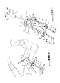
- control device of the invention is constituted according to a particular embodiment, by a support 2 formed of two parallel flanges 2a, 2b whose longitudinal edges are connected by a wall 14, said support 2 comprising at its lower part two partitions 2c, 2d respectively intended for the passage of the members 3, 4 said selection and passage connected to the gearbox (not shown).
- the aforementioned support 2 is intended to support a pin 12 said first, fixed by its two ends opposite respectively to the two flanges 2a, 2b, and around which is pivotally mounted a hub 17 extending between the two flanges 2a, 2b.
- This hub 17 is integral with a so-called second axis 5, extending perpendicular to said hub 17 and to the first axis 12, and around which a cylin sleeve is pivotally mounted.
- drique 18 on which is fixed the operating lever 1 provided with a handle 1a, perpendicular to the axis of this sleeve 18.
- This sleeve 18 comprises, at one of its opposite ends, an arm 6 mounted around said axis 5 , said arm 6 being connected by its free end to the passage cable 3a by means of a ball joint 8.
- a second arm 7 is secured by one of its ends to the aforementioned hub 17, said arm 7 extending substantially parallel to the direction of the sleeve 18 and of the second axis 5, while its another end has an axis 9 extending parallel to the hub 17 and around which the end of the other 4a of the two cables, called the selection cable, is pivotally mounted.
- the two aforementioned cables 3a, 4a respectively pass through two orifices provided respectively in the two lower partitions 2c, 2d, one of which connects the lower edges of the two flanges 2a, 2b for the purpose of stiffening, said cables being surrounded by a sheath 15, 16 provided with stop elements 10, 11 intended to be fixed against the partitions 2c, 2d.
- this assembly may be fixed by the wall 14, for example on a dashboard cross member or the like, as described in patent application No. FR-91 02 963.
- this assembly has been fixed in the passenger compartment of a vehicle so that the first axis is fixed transversely to the vehicle, from which it follows that the shifting of the ratios is effected by rotation around this axis unlike in Figure 1 in which the shift is carried out by pivoting the lever around the second axis, the direction of the lever 1 in neutral position being slightly less inclined relative to the vertical than the steering column C of the vehicle.
- a compact gearbox control assembly has been produced, on the passenger compartment side, which makes it possible to minimize position dispersions between the sheath stops and the points of attachment to the levers, this allowing positioning precise and constant shift lever in the passenger compartment.
Landscapes
- Engineering & Computer Science (AREA)
- General Engineering & Computer Science (AREA)
- Mechanical Engineering (AREA)
- Chemical & Material Sciences (AREA)
- Combustion & Propulsion (AREA)
- Transportation (AREA)
- Gear-Shifting Mechanisms (AREA)
- Arrangement Or Mounting Of Control Devices For Change-Speed Gearing (AREA)
Applications Claiming Priority (2)
| Application Number | Priority Date | Filing Date | Title |
|---|---|---|---|
| FR9204250 | 1992-04-07 | ||
| FR9204250A FR2689460B1 (fr) | 1992-04-07 | 1992-04-07 | Dispositif de commande d'une boite de vitesses de vehicule automobile. |
Publications (2)
| Publication Number | Publication Date |
|---|---|
| EP0565400A1 true EP0565400A1 (de) | 1993-10-13 |
| EP0565400B1 EP0565400B1 (de) | 1995-10-11 |
Family
ID=9428595
Family Applications (1)
| Application Number | Title | Priority Date | Filing Date |
|---|---|---|---|
| EP19930400794 Expired - Lifetime EP0565400B1 (de) | 1992-04-07 | 1993-03-26 | Steuervorrichtung für das Geschwindigkeitswechselgetriebe eines Kraftfahrzeuges |
Country Status (3)
| Country | Link |
|---|---|
| EP (1) | EP0565400B1 (de) |
| DE (1) | DE69300612T2 (de) |
| FR (1) | FR2689460B1 (de) |
Cited By (11)
| Publication number | Priority date | Publication date | Assignee | Title |
|---|---|---|---|---|
| EP0704645A1 (de) * | 1994-09-30 | 1996-04-03 | Regie Nationale Des Usines Renault S.A. | Verbesserte Vorrichtung zur Steuerung eines Getriebes mittels Kabeln |
| FR2725160A1 (fr) * | 1994-09-30 | 1996-04-05 | Renault | Dispositif perfectionne de commande de boite de vitesses par cables |
| FR2725161A1 (fr) * | 1994-09-30 | 1996-04-05 | Renault | Dispositf de commande de boite de vitesses par cables |
| EP0743475A1 (de) * | 1995-05-17 | 1996-11-20 | Société Anonyme dite: REGIE NATIONALE DES USINES RENAULT | Schaltvorrichtung für Getriebe mit räumlich versetzter Abstützung |
| EP0723096A3 (de) * | 1995-01-18 | 1997-02-05 | Sila Holding Ind S R L | Steuereinrichtung für ein Kraftfahrzeug-Schaltgetriebe |
| DE19602382A1 (de) * | 1996-01-24 | 1997-08-07 | Lemfoerder Metallwaren Ag | Außenschaltung für ein Wechselgetriebe eines Kraftfahrzeugs |
| EP0864780A1 (de) * | 1997-03-13 | 1998-09-16 | Automobiles Peugeot | Vorrichtung zum Schalten eines Geschwindigkeitswechselgetriebes eines Kraftfahrzeuges |
| EP0875413A1 (de) | 1997-04-30 | 1998-11-04 | Renault | Bowdenzugvorrichtung für Geschwindigkeitswechselgetriebe |
| EP0693391B1 (de) * | 1994-07-23 | 1998-12-09 | Bayerische Motoren Werke Aktiengesellschaft, Patentabteilung AJ-3 | Wähleinrichtung für ein Automatikgetriebe eines Kraftfahrzeugs |
| EP1431620A2 (de) | 2002-12-19 | 2004-06-23 | HONDA MOTOR CO., Ltd. | Schalthebelvorrichtung für manuelle Schaltgetriebe |
| EP1363049A3 (de) * | 2002-05-14 | 2006-11-02 | ZF Lemförder Metallwaren AG | Seilzugschaltung |
Families Citing this family (2)
| Publication number | Priority date | Publication date | Assignee | Title |
|---|---|---|---|---|
| FR2849809B1 (fr) | 2003-01-14 | 2005-03-18 | Renault Sa | Dispositif de commande deportee d'une boite de vitesses |
| FR2856960B1 (fr) | 2003-07-04 | 2005-11-18 | Renault Sa | Dispositif de commande externe de boite de vitesses pour planche de bord |
Citations (5)
| Publication number | Priority date | Publication date | Assignee | Title |
|---|---|---|---|---|
| US2821090A (en) * | 1955-08-09 | 1958-01-28 | Chrysler Corp | Transmission gearshift control mechanism |
| GB966186A (en) * | 1962-08-08 | 1964-08-06 | Gen Motors Corp | Control mechanisms |
| GB1010958A (en) * | 1964-06-12 | 1965-11-24 | Ford Motor Co | Gear shift mechanism for gearboxes for motor vehicles |
| US4712640A (en) * | 1985-12-20 | 1987-12-15 | Automotive Products Plc | Hydraulic remote control for motor vehicle manual shift transmission |
| EP0333429A2 (de) * | 1988-03-15 | 1989-09-20 | Morse Controls Limited | Fernbetätigungseinrichtung |
Family Cites Families (2)
| Publication number | Priority date | Publication date | Assignee | Title |
|---|---|---|---|---|
| JPS5936829A (ja) * | 1982-08-26 | 1984-02-29 | Chuo Spring Co Ltd | 自動車用変速機操作装置 |
| JPS6015723A (ja) * | 1983-07-07 | 1985-01-26 | Nissan Motor Co Ltd | 変速機の変速操作機構 |
-
1992
- 1992-04-07 FR FR9204250A patent/FR2689460B1/fr not_active Expired - Fee Related
-
1993
- 1993-03-26 DE DE1993600612 patent/DE69300612T2/de not_active Expired - Fee Related
- 1993-03-26 EP EP19930400794 patent/EP0565400B1/de not_active Expired - Lifetime
Patent Citations (5)
| Publication number | Priority date | Publication date | Assignee | Title |
|---|---|---|---|---|
| US2821090A (en) * | 1955-08-09 | 1958-01-28 | Chrysler Corp | Transmission gearshift control mechanism |
| GB966186A (en) * | 1962-08-08 | 1964-08-06 | Gen Motors Corp | Control mechanisms |
| GB1010958A (en) * | 1964-06-12 | 1965-11-24 | Ford Motor Co | Gear shift mechanism for gearboxes for motor vehicles |
| US4712640A (en) * | 1985-12-20 | 1987-12-15 | Automotive Products Plc | Hydraulic remote control for motor vehicle manual shift transmission |
| EP0333429A2 (de) * | 1988-03-15 | 1989-09-20 | Morse Controls Limited | Fernbetätigungseinrichtung |
Non-Patent Citations (2)
| Title |
|---|
| PATENT ABSTRACTS OF JAPAN vol. 8, no. 137 (P-282)26 Juin 1984 & JP-A-59 036 829 ( CHIYUUOU HATSUJIYOU K.K. ) 29 Février 1984 * |
| PATENT ABSTRACTS OF JAPAN vol. 9, no. 133 (P-362)(1856) 8 Juin 1985 & JP-A-60 15 723 ( NISSAN JIDOSHA K.K. ) 26 Janvier 1985 * |
Cited By (16)
| Publication number | Priority date | Publication date | Assignee | Title |
|---|---|---|---|---|
| EP0693391B1 (de) * | 1994-07-23 | 1998-12-09 | Bayerische Motoren Werke Aktiengesellschaft, Patentabteilung AJ-3 | Wähleinrichtung für ein Automatikgetriebe eines Kraftfahrzeugs |
| EP0704645A1 (de) * | 1994-09-30 | 1996-04-03 | Regie Nationale Des Usines Renault S.A. | Verbesserte Vorrichtung zur Steuerung eines Getriebes mittels Kabeln |
| FR2725160A1 (fr) * | 1994-09-30 | 1996-04-05 | Renault | Dispositif perfectionne de commande de boite de vitesses par cables |
| FR2725161A1 (fr) * | 1994-09-30 | 1996-04-05 | Renault | Dispositf de commande de boite de vitesses par cables |
| EP0723096A3 (de) * | 1995-01-18 | 1997-02-05 | Sila Holding Ind S R L | Steuereinrichtung für ein Kraftfahrzeug-Schaltgetriebe |
| EP0743475A1 (de) * | 1995-05-17 | 1996-11-20 | Société Anonyme dite: REGIE NATIONALE DES USINES RENAULT | Schaltvorrichtung für Getriebe mit räumlich versetzter Abstützung |
| FR2734214A1 (fr) * | 1995-05-17 | 1996-11-22 | Renault | Dispositif de commande d'une boite de vitesses muni d'un bati deporte |
| DE19602382A1 (de) * | 1996-01-24 | 1997-08-07 | Lemfoerder Metallwaren Ag | Außenschaltung für ein Wechselgetriebe eines Kraftfahrzeugs |
| FR2760698A1 (fr) * | 1997-03-13 | 1998-09-18 | Peugeot | Dispositif de commande d'une boite de vitesses de vehicule automobile |
| EP0864780A1 (de) * | 1997-03-13 | 1998-09-16 | Automobiles Peugeot | Vorrichtung zum Schalten eines Geschwindigkeitswechselgetriebes eines Kraftfahrzeuges |
| US5934146A (en) * | 1997-03-13 | 1999-08-10 | Automobiles Peugot | Device for controlling the transmission of an automobile |
| EP0875413A1 (de) | 1997-04-30 | 1998-11-04 | Renault | Bowdenzugvorrichtung für Geschwindigkeitswechselgetriebe |
| FR2762808A1 (fr) | 1997-04-30 | 1998-11-06 | Renault | Dispositif de commande par cables d'une boite de vitesses |
| EP1363049A3 (de) * | 2002-05-14 | 2006-11-02 | ZF Lemförder Metallwaren AG | Seilzugschaltung |
| EP1431620A2 (de) | 2002-12-19 | 2004-06-23 | HONDA MOTOR CO., Ltd. | Schalthebelvorrichtung für manuelle Schaltgetriebe |
| EP1431620A3 (de) * | 2002-12-19 | 2007-08-22 | HONDA MOTOR CO., Ltd. | Schalthebelvorrichtung für manuelle Schaltgetriebe |
Also Published As
| Publication number | Publication date |
|---|---|
| DE69300612T2 (de) | 1996-04-04 |
| EP0565400B1 (de) | 1995-10-11 |
| FR2689460A1 (fr) | 1993-10-08 |
| FR2689460B1 (fr) | 1996-10-11 |
| DE69300612D1 (de) | 1995-11-16 |
Similar Documents
| Publication | Publication Date | Title |
|---|---|---|
| EP0565400B1 (de) | Steuervorrichtung für das Geschwindigkeitswechselgetriebe eines Kraftfahrzeuges | |
| FR2728042A1 (fr) | Changement de vitesses a engrenages pour un vehicule automobile | |
| FR2589545A1 (fr) | Dispositif de stationnement pour une transmission automatique | |
| EP0072464B1 (de) | Handsteuervorrichtung für die Gänge eines Wechselgetriebes | |
| EP0560645B1 (de) | Gangschalthebelvorrichtung, insbesondere für Kraftfahrzeuge | |
| EP0756112B1 (de) | Steuerhebelanordnung mit verbesserter Positionsarretierung | |
| FR2742513A1 (fr) | Dispositif de selection pour un mecanisme de changement de vitesse d'un vehicule a moteur | |
| EP0751322B1 (de) | Fahrzeug-Gangschalthebel mit Kraftaufnehmer | |
| EP0864780B1 (de) | Vorrichtung zum Schalten eines Gangwechselgetriebes eines Kraftfahrzeuges | |
| EP0743475B1 (de) | Schaltvorrichtung für Getriebe mit räumlich versetzter Abstützung | |
| FR2737160A1 (fr) | Ensemble de commande a levier comprenant des moyens de verrouillage perfectionnes | |
| FR2694615A1 (fr) | Dispositif d'actionnement de transmission. | |
| EP0524059B1 (de) | Schaltvorrichtung für ein Getriebe | |
| EP2173603A1 (de) | Kabel- und/oder stangensteuerungssystem für ein getriebe eines schwerlastfahrzeugs mit kippkabine | |
| FR2676843A1 (fr) | Dispositif de commande manuelle pour une commande a distance par cables flexibles, notamment pour la commande de changement de vitesse d'une boite de vitesses. | |
| EP0084472A1 (de) | Verstelleinrichtung für Schaltgetriebe | |
| FR2793197A1 (fr) | Dispositif de commande d'une boite de vitesses de vehicule automobile | |
| FR2848153A1 (fr) | Vehicule automobile equipe d'un dispositif de commande de boite de vitesses magnetique | |
| EP0611671B1 (de) | Steuergerät für manuelle und automatische Regelung der Fahrzeughöhe in einem Kraftfahrzeug mit hydropneumatischer Aufhängung | |
| FR3113384A1 (fr) | Dispositif de commande par cables de la selection de rapports d'une boîte de vitesses de vehicule automobile | |
| FR2597947A1 (fr) | Derailleur avant pour une bicyclette | |
| FR2747623A1 (fr) | Dispositif pour la commande manuelle d'une boite de vitesses de vehicule | |
| FR2849809A1 (fr) | Dispositif de commande deportee d'une boite de vitesses | |
| FR2762808A1 (fr) | Dispositif de commande par cables d'une boite de vitesses | |
| FR2696254A1 (fr) | Tringlerie de commande du changement de vitesses d'un véhicule automobile. |
Legal Events
| Date | Code | Title | Description |
|---|---|---|---|
| PUAI | Public reference made under article 153(3) epc to a published international application that has entered the european phase |
Free format text: ORIGINAL CODE: 0009012 |
|
| AK | Designated contracting states |
Kind code of ref document: A1 Designated state(s): DE GB IT |
|
| 17P | Request for examination filed |
Effective date: 19940411 |
|
| 17Q | First examination report despatched |
Effective date: 19950320 |
|
| GRAA | (expected) grant |
Free format text: ORIGINAL CODE: 0009210 |
|
| AK | Designated contracting states |
Kind code of ref document: B1 Designated state(s): DE GB IT |
|
| REF | Corresponds to: |
Ref document number: 69300612 Country of ref document: DE Date of ref document: 19951116 |
|
| ITF | It: translation for a ep patent filed | ||
| GBT | Gb: translation of ep patent filed (gb section 77(6)(a)/1977) |
Effective date: 19951127 |
|
| PLBE | No opposition filed within time limit |
Free format text: ORIGINAL CODE: 0009261 |
|
| 26N | No opposition filed | ||
| REG | Reference to a national code |
Ref country code: GB Ref legal event code: IF02 |
|
| PGFP | Annual fee paid to national office [announced via postgrant information from national office to epo] |
Ref country code: GB Payment date: 20020327 Year of fee payment: 10 |
|
| PGFP | Annual fee paid to national office [announced via postgrant information from national office to epo] |
Ref country code: DE Payment date: 20020404 Year of fee payment: 10 |
|
| PG25 | Lapsed in a contracting state [announced via postgrant information from national office to epo] |
Ref country code: GB Free format text: LAPSE BECAUSE OF NON-PAYMENT OF DUE FEES Effective date: 20030326 |
|
| PG25 | Lapsed in a contracting state [announced via postgrant information from national office to epo] |
Ref country code: DE Free format text: LAPSE BECAUSE OF NON-PAYMENT OF DUE FEES Effective date: 20031001 |
|
| GBPC | Gb: european patent ceased through non-payment of renewal fee |
Effective date: 20030326 |
|
| PG25 | Lapsed in a contracting state [announced via postgrant information from national office to epo] |
Ref country code: IT Free format text: LAPSE BECAUSE OF NON-PAYMENT OF DUE FEES;WARNING: LAPSES OF ITALIAN PATENTS WITH EFFECTIVE DATE BEFORE 2007 MAY HAVE OCCURRED AT ANY TIME BEFORE 2007. THE CORRECT EFFECTIVE DATE MAY BE DIFFERENT FROM THE ONE RECORDED. Effective date: 20050326 |