EP0565406A1 - Procédé pour fabriquer un corps en forme d'anneau - Google Patents
Procédé pour fabriquer un corps en forme d'anneau Download PDFInfo
- Publication number
- EP0565406A1 EP0565406A1 EP93400820A EP93400820A EP0565406A1 EP 0565406 A1 EP0565406 A1 EP 0565406A1 EP 93400820 A EP93400820 A EP 93400820A EP 93400820 A EP93400820 A EP 93400820A EP 0565406 A1 EP0565406 A1 EP 0565406A1
- Authority
- EP
- European Patent Office
- Prior art keywords
- ring body
- roll
- stock material
- forming
- metallic ring
- Prior art date
- Legal status (The legal status is an assumption and is not a legal conclusion. Google has not performed a legal analysis and makes no representation as to the accuracy of the status listed.)
- Withdrawn
Links
- 238000004519 manufacturing process Methods 0.000 title claims abstract description 107
- 239000000463 material Substances 0.000 claims abstract description 164
- 238000007493 shaping process Methods 0.000 claims abstract description 91
- 230000008859 change Effects 0.000 claims abstract description 26
- 230000002093 peripheral effect Effects 0.000 claims description 72
- 238000000034 method Methods 0.000 claims description 65
- 230000000994 depressogenic effect Effects 0.000 claims description 10
- 238000005097 cold rolling Methods 0.000 claims description 6
- 230000000452 restraining effect Effects 0.000 claims description 5
- 238000000137 annealing Methods 0.000 claims description 4
- 238000003825 pressing Methods 0.000 claims description 4
- 238000000926 separation method Methods 0.000 claims description 2
- 238000002485 combustion reaction Methods 0.000 claims 1
- 230000006835 compression Effects 0.000 abstract description 9
- 238000007906 compression Methods 0.000 abstract description 9
- 230000002079 cooperative effect Effects 0.000 abstract 1
- 230000008569 process Effects 0.000 description 17
- 238000003754 machining Methods 0.000 description 14
- 230000009471 action Effects 0.000 description 8
- 239000002184 metal Substances 0.000 description 8
- 229910052751 metal Inorganic materials 0.000 description 8
- 230000015572 biosynthetic process Effects 0.000 description 7
- 239000007769 metal material Substances 0.000 description 3
- 238000005096 rolling process Methods 0.000 description 3
- 230000007704 transition Effects 0.000 description 3
- PXHVJJICTQNCMI-UHFFFAOYSA-N Nickel Chemical compound [Ni] PXHVJJICTQNCMI-UHFFFAOYSA-N 0.000 description 2
- 239000000956 alloy Substances 0.000 description 2
- 229910045601 alloy Inorganic materials 0.000 description 2
- 230000009466 transformation Effects 0.000 description 2
- 238000000844 transformation Methods 0.000 description 2
- 229910000831 Steel Inorganic materials 0.000 description 1
- 229910017052 cobalt Inorganic materials 0.000 description 1
- 239000010941 cobalt Substances 0.000 description 1
- GUTLYIVDDKVIGB-UHFFFAOYSA-N cobalt atom Chemical compound [Co] GUTLYIVDDKVIGB-UHFFFAOYSA-N 0.000 description 1
- 230000003247 decreasing effect Effects 0.000 description 1
- 238000009826 distribution Methods 0.000 description 1
- 230000000694 effects Effects 0.000 description 1
- 239000012467 final product Substances 0.000 description 1
- 238000005098 hot rolling Methods 0.000 description 1
- 230000013011 mating Effects 0.000 description 1
- 229910052759 nickel Inorganic materials 0.000 description 1
- 230000004044 response Effects 0.000 description 1
- 239000007787 solid Substances 0.000 description 1
- 239000010959 steel Substances 0.000 description 1
Images




Classifications
-
- B—PERFORMING OPERATIONS; TRANSPORTING
- B21—MECHANICAL METAL-WORKING WITHOUT ESSENTIALLY REMOVING MATERIAL; PUNCHING METAL
- B21H—MAKING PARTICULAR METAL OBJECTS BY ROLLING, e.g. SCREWS, WHEELS, RINGS, BARRELS, BALLS
- B21H1/00—Making articles shaped as bodies of revolution
- B21H1/06—Making articles shaped as bodies of revolution rings of restricted axial length
Definitions
- This invention relates to a method of making a metallic ring body having surface shapes on either the inner or the outer peripheral surface of the ring body, and in particular to fabricating the surface shapes by roll forming.
- a method of making metallic rings for use in gas turbine engines is disclosed in a Japanese patent application Sho 62-2889. The method discloses, in part:
- the present invention of fabricating surface shapes on an inner or an outer ring surface of a ring body is concerned with achieving the following objectives:
- a method for fabricating surface shapes on eitherthe inner surface or the outer peripheral surface of a metallic ring body.
- the axial direction is the direction of the ring axis and the radial direction is the direction in the ra- dius/diameterdirection of the ring body
- a peripheral surface refers either to an inner or an outer peripheral surface of the ring body.
- the method of fabricating surface shapes on a peripheral surface of the ring body by roll forming comprises the steps of:
- the fabrication process further includes at least one of the following processing steps:
- the roll forming process is controlled by one parameter, i.e. one of the inner diameter, the outer diameter and the axial dimension, the process prevents a generation of rejects caused by off-tolerance of one critical parameter, as well as improving the subsequent fabrication efficiency.
- a ring body stands vertically with the ring axis lying horizontally in the plane of the paper, and the drawings show only one side of the cross section made through the ring axis, viewed in the direction of the diameter of the ring body.
- the outer roll is shown on the top, and the inner roll is shown at the bottom, unless otherwise shown.
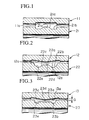
- Figure 1 shows a front cross sectional view of the forming rolls used in a first embodiment of the method of forming shapes on an inner peripheral surface of a ring body.
- Figure 2 shows a front cross sectional view of the forming rolls used in the intermediate fabrication stage of the first embodiment.
- Figure 3 shows a front cross sectional view of the forming rolls used in the final fabrication stage of the
- a metallic stock material 1 having the dimensions of 242 mm innerdiameter, 14 mm wall thickness and 46 mm width, and having a rectangular cross sectional shape, shown in Figure 4 (a), was made of AM 5754 steel mentioned above.
- the stock material 1 had a smaller inner diameter and a larger axial cross sectional area compared with either the final ring body stock 4 shown by the solid line in Figure 4 (f), orthe completed ring body 5 shown by the dotted line in Figure 4 (f).
- the parts on the forming rolls are referred to as "sections” while the parts on the stock material are referred to as "regions” to avoid confusing between similarly shaped sections of the forming rolls and the mating ring body.
- the completed ring body 5 is produced from stock material 1 through various stages of rolling the ring body stock, 2, 3, 4 into the final product as a metallic ring-shaped body or simply ring body.
- a metallic ring body (either the final ring body stock 4 or the completed ring body 5) having surface shapes on the inner peripheral surface is made by a four-stage fabrication process: initial, intermediate and final roll forming fabrication stages, and the machine fabrication stage.
- the initial fabrication stage consists of compression rolling of the stock material 1 between a pair of initial stage forming rolls consisting of an outer roughing-roll 11 and an inner rough shaping-roll 21, shown in Figure 1, to produce an initial roll formed ring body stock 2 (shortened to initial body 2).
- the intermediate fabrication stage consists of compression roll forming of the initial ring body stock 2 between a pair of intermediate stage forming rolls consisting of an outer intermediate forming roll 12 and an inner intermediate shaping roll 22, shown in Figure 2, to produce an intermediate rolled ring body stock 3.
- the final fabrication stage consists of compression roll forming the intermediate rolled ring body stock 3 between a pair of an outer finishing roll 13 and an innerfinish shaping roll 23, shown in Figure 3, to produce a final ring body stock 4.
- the final ring body stock4 is finish machined to remove excess materials to produce a completed ring body 5.
- the various steps in the three fabrication stages are illustrated in Figures 4 (a) to (f).
- the various steps of roll forming are performed by cold rolling to prevent phase transformations of the hard stock material, such as AM 5754, and various annealing steps are involved to soften the material to improve the subsequent fabrication steps.
- the forming rolls to produce shapes are termed shaping rolls and, in the first embodiment, an inner roll is used to produce shapes on the inner peripheral surface of the ring body illustrated in Figures 1 to 3. Therefore, the inner roll is the shaping roll in this case.
- the outer roll in this case produces a lesser degree of deformation in the stock material, and is termed a forming roll.
- the outer forming roll 11 (top) is provided with a retaining depression 11a, as shown in Figure 1, of a cylindrical shape extending around the inner peripheral surface of the roll parallel to the ring axis, so as to be in a plane contact and hold the outer peripheral surface of the stock material during the initial fabrication stage.
- the outer intermediate roll 12, in Figure 2 is provided with a protruding taper forming section 12a, formed symmetrically about the ring axis, and whose central section is protruding in the radial direction (shown protruding downward in Figure 2).
- the outer finishing roll 13 is also provided with a taper forming section 13a, as shown in Figure 3, having the same profile shape as that for the outer intermediate roll 12.
- the profile shape is arranged so that some rolls can be interchanged between the intermediate and final stages of fabrication.
- the inner rough shaping roll 21 for the initial fabrication stage is provided, as shown in Figure 1, with a ring-shaped protrusion section (RSPS) 21a and the forming channels 21 b on both sides of the protrusion section 21a, and a sloped section 21c disposed around the RSPS 21a merging the RSPS 21a with the forming channels 21 b.
- the RSPS 21 a is shaped cylindrically, and is provided with a cylindrical side surface which extends parallel to the axial direction.
- the inner intermediate shaping roll 22 is also provided, as shown in Figure 2, with an axially centrally disposed ring-shaped protrusion section RSPS 22a, the forming cavities 22b and the sloped section 22c.
- RSPS 22a In the center of the RSPS 22a is a slightly depressed small depression section 22d, and the retaining section 22b is provided with an innerforming section 22e.
- the sloped section 22c is shaped so that the slope of the surface is the same as that shown in Figure 1, but the sloped length is longer than that shown in Figure 1 so as to make deeper forming channels.
- the inner finish shaping roll 23 is provided, as shown in Figure 3, with a protrusion RSPS 23a, which extends wider axially compared with that shown in Figure 2, and surrounded by a retaining section 23b defined by the inner shaping section 23e, which is shorter than that shown in Figure 2.
- the finish shaping roll 23 also has a sloped section 23c surrounding the protrusion 23a, and a small depression 23d, having a gently sloped surface, and disposed in the center of the protrusion RSPS 23a.
- a stock material 1 having a cross sectional shape of dimensions shown in Figure 4 (a) is placed as shown in Figure 1 between the outer-roughing roll 11 and the inner rough shaping roll 21, and is processed through the steps shown in Figures 4 (b) to (c) to produce the various shapes and sizes of the ring bodies shown in Figures 4 (b) to (c).
- roll forming steps are repeated from fifty to five hundred times, preferably around three hundred times, to produce an initial ring body stock 2 of a shape shown in Figure 4 (c).
- the central region of the stock material 1 subjected to a high contact pressure is plastically spread out, and because the contact surface between the stock material 1 and the retaining depression 11a is planar and parallel tothe axial direction, the compressed material flows so that the stock material 1 becomes distributed primarily to increase the wall thickness on the inner peripheral surface of the stock material 1, i.e. away from the regions in contact with the RSPS 21a of the inner rough shaping roll 21.
- the intermediate fabrication stage is performed by placing the initial ring body stock 2 between the outer intermediate roll 12 and the inner intermediate shaping roll 22, as shown in Figure 2.
- roll forming steps are repeated from fifty to five hundred times, preferably around three hundred times, for example, to produce an intermediate ring body stock 3 of a shape shown in Figure 4 (d).
- the positional alignment of the ring body stock 2 is achieved when the initial ring body stock 2 is deformed such that the region of the stock material in contact with protrusion section RSPS 22a becomes merged the region of the stock material in contact with the sloped section 22c.
- Roll forming is continued further by engaging the ring-shaped depression region RSDR 3a of the ring body stock 3 with the protrusion section RSPS 22a and the sloped section 22c of the inner intermediate shaping roll 22, thereby retaining the ring body stock 3 in place, and preventing the axial shift of the ring body stock 3. Therefore, even for the case of deforming the outer peripheral surface of the ring body stock 3 in contact with the taper forming surface 12a of the outer shaping roll 12 to produce the outer tapered section 3b, the retaining effect is operative to prevent the axial shift of the ring body stock 3, thereby enabling redistribution of the stock material in the axial direction to take place smoothly and uniformly.
- the degree of deformation associated with the roll forming of the outer peripheral surface is relatively mild (which refers to the formation of outer tapered surface 3b by the taper forming section 12a).
- the stock material becomes redistributed progressively from the central region to the axial extremities of the ring body stock 3 thus forming the central thin section 3c surrounded by the thick sections 3d (shaped sections) of the intermediate ring body stock 3.
- Final fabrication stage is carried out by placing the intermediate ring body stock 3 between the outer finishing roll 13 and the inner finish shaping roll 23.
- roll forming steps are repeated from fifty to five hundred times, preferably around three hundred times, for example, to produce a final ring body stock 4 of a shape shown in Figure 4 (f).
- the positional alignment is carried out by placing the taper forming surface 13a of the outer finishing roll 13 in contact with the outer tapered regions 3b of the intermediate ring body stock 3.
- the final ring body stock 4 shown in Figures 4 (e) and (f) is fabricated by engaging the protrusion RSPS 23a of the inner finish shaping roll 23 with the small depression region 3a of the intermediate ring body stock 3.
- the deformation of the stock material is primarily concentrated on the inner peripheral surface, because the taper forming section 12a, 13a of the outer rolls 12 and 13, shown in Figures 2 and 3, have the same size and shape, and consequently there is little deformations taking place there.
- the final ring body stock 4 is rolled formed to the shape shown by the solid line in Figure 4 (f) as described above, leaving the excess material to be machined off as shown by the dotted line.
- Two completed ring body 5 of identical shape and sizes are produced by either parting at the line X-Y and machining to size, or by grinding first and parting next.
- the ring body sizes are chosen so as to minimize the excess material to be machined off, however, to increase machining precision and/or production efficiency the material removed may range from 30-60 % and preferably around 40 %.
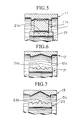
- Figures 5 to 8 show a second embodiment of forming shapes on the inner peripheral surface of a ring body.
- the shaping roll is again the inner forming roll.
- various forming rolls shown in Figures 5 to 8 are employed to produce the finished ring body stock 4 shown in Figure 8. They are an outer roughing roll 11 and an inner rough shaping roll 21 shown in Figure 5, outer intermediate forming roll 12 and inner rough shaping roll 21 shown in Figure 6, and an outer finishing roll 13 and inner finish shaping roll 23 shown in Figure 7.
- the inner rough shaping roll 21 is shared in forming the various intermediate shapes.
- a gap G between the inner roll and the outer roll is maintained during the forming steps using the forming rolls shown in Figures 5 to 8 so as to permit easy flow of the stock material in the axial direction of the ring body.
- the gap G operates effectively to provide the material flow in the initial forming stage by engaging the outer peripheral surface of the stock material 1 with the retaining depression 11a thus controlling the material flow in the axial direction at the outer peripheral surface of the stock material 1; and in the intermediate fabrication stage, because the inner rough shaping roll 21 is shared between the initial and the intermediate stages, the RSPS 21 a of the inner rough shaping roll 21 is engaged with the inner peripheral surface of the stock material 1, thereby preventing the axial flow of the stock material as well as the shifting of the axis during the intermediate forming operation.
- the ring body is subjected to the final fabrication process to produced a completed ring body.
- the roll forming method of the present invention can be applied to manufacturing of other ring-shaped bodies of the following shapes.
- Athird embodiment is concerned with an application of the fabrication method of the present invention to a ring body having a shape change region on the outer peripheral surface.
- the shapes are produced by pressing the outer peripheral surface of a stock material against the inner surface of an outer forming roll, therefore, the outer forming roll becomes the shaping roll in the third embodiment.
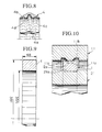
- the embodiment will be explained with reference to Figures 9-15.
- a metallic stock material 1 shown in Figure 9 is made of a material such as AM 5754, for example, and has a rectangular cross sectional shape with an outer diameter 381 mm, an inner diameter 355 mm and a width of 48 mm.
- the starting metallic material 1 is shaped larger than both the final ring body stock4 and the completed ring body 5, illustrated in Figure 14 by solid and dotted lines.
- the outer roughing roll is now a shaping roll, and is termed an outer rough shaping roll 11, and it comprises: a RSPS 11 disposed in an axial middle section; a shaping channel 11b disposed on each axial sides of the RSPS 11a; a tapered region 11c disposed on both sides of the RSPS 11a; and wherein the RSPS 11a has a cylindrical surface formed along the inner circumferential surface of the outer forming roll, in parallel to the axial direction of the stock material 1.
- the outer intermediate shaping roll 12 comprises: a RSPS 12a; a shaping channel 12b disposed on each axial side of the RSPS 12a; wherein the RSPS 12a is formed as a two step mound section, and the shaping channel 12b is provided with a transition shaping section 12d.
- the outer finish shaping roll 13 comprises: a RSPS 13p disposed in an axial middle section; a shaping channel 13b disposed on each axial side of the RSPS 13p; an outer forming section 13c; and a transition section 13d, and wherein the width of the RSPS 13p of the outerfinish shaping roll 13 is larger than the RSPS 12a of the outer intermediate shaping rolls 12.
- the inner rough forming roll 21 is provided with a flat bottomed retaining section 21 a.
- the inner intermediate roll 22 is provided with an axially symmetrical taper forming section 22t which is formed centrally and is depressed towards the center.
- the inner finish forming roll 23 is also provided with an axially symmetrical taper forming section 23t which is formed centrally and is depressed towards the center.
- This finish forming roll 23 is interchangeable with the intermediate forming roll 22, in other words, by maintaining the same profile of the tapered sections, a roll can be shared between the two stages.
- forming operation is carried out, as shown in Figure 10, by disposing a stock material 1 between the outer rough shaping roll 11 and the inner rough forming roll 21, as shown in Figure 10.
- roll forming steps are repeated from fifty to five hundred times, preferably around three hundred times, to produce an initial ring body stock 2, shown in Figure 11.
- the RSDR2a is formed at the specific location, i.e. the central region of the stock material 1 in Figure 10.
- the regions of contact under high pressures are deformed, and because the retaining section 21a is flat, the material flow takes place primarily in the direction perpendicular to the contact surface between the RSPS 11a of the outer rough shaping roll 11 and the stock material 1.
- the stock material is allowed to flow in the axial direction as the roll forming process is continued, thus gradually increasing the axial dimensions and the inner diameter of the stock material while decreasing the effective cross sectional area of the stock material in the axial direction.
- the intermediate fabrication stage is performed by holding the initial ring body stock 2 between the outer intermediate shaping roll 12 and the inner intermediate forming roll 22.
- the roll forming operations are repeated, for example, from fifty to five hundred times, preferably about three hundred times to obtain an intermediate ring body stock 3 shown in Figure 12.
- roll forming of the initial ring body stock 2 is carried out by pressing the ring body stock 2 between the outer intermediate shaping roll 12 and the inner intermediate forming roll 22 while supporting the inner peripheral surface of the ring body stock 2 with the taperforming section 22t of the inner intermediate forming roll 22 and engaging the initial RSDR 2a of the initial ring body stock 2 with the RSPS 12a of the outer intermediate shaping roll 12.
- Deformations occur at the regions of the ring body stock 2 under high contact pressure, such as between the RSPS 12a and the initial RSDR 2a on the one hand and between the taper forming section 22t and the inner peripheral surface of the ring body stock 2.
- the result is a formation of an intermediate ring-shaped body 2 showing a curved cross sectional shape.
- the deformation processing is carried out by engaging the RSDR2a with the RSPS 12a, the shifting of the intermediate ring body stock 2 in the axial direction is prevented, and the formation of the tapered region of the ring body stock 2 in contact with the taper forming section 22t of the finish forming roll 23 can take place without any axial shifting, thus allowing the stock material to be distributed evenly and smoothly in the axial direction.
- the gap G between the outer intermediate shaping roll 12 and the inner intermediate forming roll 22 is maintained also during the intermediate fabrication stage. Therefore, the result of enlarging the initial RSDR 2a of the initial ring body stock 2 by the pressing action of the RSPS 12a of the outer initial shaping roll 12 is the formation of the intermediate RSDR 3a of the intermediate ring body stock 3, shown in Figure 12, brought about by the radial compression of the stock material leading to the flow of the stock material in the axial direction.
- the intermediate RSDR 3a is formed on the outer peripheral surface of the ring body stock 2 by the action of the RSPS 12a; the thick shape change region 3b, 3c on the outer peripheral surface of the ring body stock 2 are formed by the action of the outer peripheral surface forming section 12c and the transition shaping section 12d; and the taper forming surface 3d is formed on the inner peripheral surface of the ring body stock 2 by the taper forming section 22t of the inner intermediate forming roll 22.
- the RSPS 12a is continuously engaged with the RSDR 2a of the stock material, and together with the compression action of the ring body stock 2 by the outer peripheral surface forming section 12b, the overall result is the deepening of the initial RSDR 2a in the radial direction and the widening thereof in the axial direction, thus achieving distribution of the stock material evenly on both sides of the initial RSDR 2 in the axial direction.
- the taper region 3d of the ring body stock 2 is being formed by the taper forming section 22t of the inner intermediate forming roll 22, but the degree of deformation of the inner region of the ring body stock 2 is somewhat restricted by the taper forming section 22t, and the result is a tendency for a relatively greater transfer of the stock material in the outer peripheral surface region of the ring body stock 2.
- roll forming is carried out by placing the intermediate ring body stock 3 between the outerfinish shaping roll 13 and the inner finish forming roll 23 as shown in Figure 12.
- the roll forming operations are repeated, for example, from fifty to five hundred times, preferably about three hundred times to obtain an intermediate ring body stock 3 shown in Figure 12.
- the axial shifting of the ring body stock 3 is prevented and the dimensional precision is improved by engaging the intermediate RSDR 3a of the ring body stock 3 with the RSPS 13p of the outer finish shaping roll 13; and by engaging both tapered surface regions of the ring body stock 3 with the taperforming section 23t of the inner finish forming roll 23.
- the forming of the ring body stock 3 during the final fabrication stage takes place primarily in the outer peripheral regions of the ring body stock 3 because the inner rolls 22, 23 are shared between the two forming stages, and the taper forming sections 22t, 23t of the inner rolls 22, 23 are the same shape as shown by Figures 11 and 12, respectively, for the intermediate fabrication and the final fabrication stages.
- the RSPS 13p of the outer finish shaping roll 13 carries out the widening of the intermediate RSDR 3a of the intermediate ring body stock 3 in the axial direction to produce the final RSDR 4a; and the outer peripheral surface forming section 13c forms the shape change region 4c and the shape change section 4d which extends in the axial direction into the region 4c.
- the excess materials is represented by the difference between a solid line and a dotted line, and is removed by suitable means such as machining and grinding.
- the final ring body stock4 shaped by a series of forming steps to the shape shown by the solid line in Figure 14, is represented by the solid line, and the dotted line represents the completed ring body 5.
- the excess material represented by the difference between the two lines is removed by machining fabrication.
- the completed ring body 5 can be produced by either parting the final ring body stock 4 at the line X-Y and machining the individual part, or by separating the final ring body stock 4 at the time of machining or grinding.
- the ring body sizes are chosen so as to minimize the excess material to be machined off, however, to increase machining precision and/or production efficiency the material removed may range from 30-60 % and preferably about 40 %.
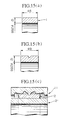
- Figure 15 illustrates a fourth embodiment in which a series of forming operations are carried out to produce a ring body having a shape change region in the outer peripheral surface by a pair of forming rolls.
- the complete processing involves the steps illustrated from (a) thorough to (g), and the outer rough shaping roll 11 and the inner rough forming roll 21 shown in (c) are used to perform the initial fabrication steps; and the outer finish shaping roll 13 and the inner finish forming roll 23 shown in (f) are used to perform the finish rolling steps.
- the finish shaping rolls 13, 23 are shared between the finishing and the intermediate roll forming stages.
- a gap G is maintained between the pairs of outer and inner rolls to enable the deformation of the ring body to take place in the axial direction in accordance with the examples illustrated in Figures 10 to 14.
- a shape change region 4b of some thickness is left in the central region of the final ring body stock 4.
- the stock material in these regions is subjected to a large amount of axial deformation so as to produce shape change section 4c of a relatively thin cross sectional thickness.
- the method of roll forming of the present invention can be applied to manufacturing of the ring shaped bodies of the following shapes.
Landscapes
- Engineering & Computer Science (AREA)
- Mechanical Engineering (AREA)
- Forging (AREA)
Applications Claiming Priority (4)
| Application Number | Priority Date | Filing Date | Title |
|---|---|---|---|
| JP08410692A JP3282210B2 (ja) | 1992-04-06 | 1992-04-06 | 内周に形状変化部を持つ金属リング体の製造方法 |
| JP84106/92 | 1992-04-06 | ||
| JP08410792A JP3282211B2 (ja) | 1992-04-06 | 1992-04-06 | 外周に形状変化部を持つ金属リング体の製造方法 |
| JP84107/92 | 1992-04-06 |
Publications (1)
| Publication Number | Publication Date |
|---|---|
| EP0565406A1 true EP0565406A1 (fr) | 1993-10-13 |
Family
ID=26425182
Family Applications (1)
| Application Number | Title | Priority Date | Filing Date |
|---|---|---|---|
| EP93400820A Withdrawn EP0565406A1 (fr) | 1992-04-06 | 1993-03-30 | Procédé pour fabriquer un corps en forme d'anneau |
Country Status (2)
| Country | Link |
|---|---|
| US (1) | US5412967A (fr) |
| EP (1) | EP0565406A1 (fr) |
Cited By (1)
| Publication number | Priority date | Publication date | Assignee | Title |
|---|---|---|---|---|
| EP1270111A1 (fr) * | 2001-06-26 | 2003-01-02 | Johann Hay GmbH & Co. KG, Automobiltechnik | Procédé et dispositif pour la fabrication d'une piece ayant une symetrie de revolution |
Families Citing this family (7)
| Publication number | Priority date | Publication date | Assignee | Title |
|---|---|---|---|---|
| US6391172B2 (en) | 1997-08-26 | 2002-05-21 | The Alta Group, Inc. | High purity cobalt sputter target and process of manufacturing the same |
| KR20030023640A (ko) * | 2000-06-30 | 2003-03-19 | 허니웰 인터내셔널 인코포레이티드 | 금속처리방법, 그 방법에 사용되는 장치 및 그로부터제조된 금속 |
| US6629415B2 (en) | 2001-10-27 | 2003-10-07 | General Electric Co. | Methods and apparatus for modeling gas turbine engine combustor liners |
| US7007386B1 (en) | 2002-12-20 | 2006-03-07 | General Sullivan Group, Inc. | Light duty bearing assembly |
| CN112792269B (zh) * | 2021-01-14 | 2023-04-14 | 重庆大学 | 一种确保矩形环件轧制过程环件刚度的方法 |
| CN113199216B (zh) * | 2021-05-14 | 2022-10-28 | 上海江丰平芯电子科技有限公司 | 一种不锈钢夹环的制备方法 |
| CN115121749A (zh) * | 2022-05-30 | 2022-09-30 | 无锡市盛宝嘉科技有限公司 | 多工位碾环机上下料机械臂 |
Citations (5)
| Publication number | Priority date | Publication date | Assignee | Title |
|---|---|---|---|---|
| CS124200A (fr) * | ||||
| US3626564A (en) * | 1970-02-26 | 1971-12-14 | Lear Siegler Inc | Manufacture of bearing races |
| US3999416A (en) * | 1975-10-24 | 1976-12-28 | General Electric Company | Cold rolling a contour in metal rings |
| FR2418045A1 (fr) * | 1978-02-24 | 1979-09-21 | Gen Electric | Procede et appareil pour la fabrication d'anneaux |
| US4476194A (en) * | 1982-11-10 | 1984-10-09 | United Technologies Corporation | Contour forming conical shapes |
Family Cites Families (4)
| Publication number | Priority date | Publication date | Assignee | Title |
|---|---|---|---|---|
| US4016739A (en) * | 1975-12-08 | 1977-04-12 | Vladimir Viktorovich Lapin | Method of shaping ring blanks |
| SU694261A1 (ru) * | 1977-02-01 | 1979-10-30 | Московское Высшее Техническое Училище Им. Баумана | Устройство дл раскатки колец |
| FR2407033A1 (fr) * | 1977-10-31 | 1979-05-25 | Honda Motor Co Ltd | Procede de fabrication de jantes de roues sans soudure |
| JPS6481936A (en) * | 1987-09-25 | 1989-03-28 | Ricoh Kk | Synthetic copying device |
-
1993
- 1993-03-30 EP EP93400820A patent/EP0565406A1/fr not_active Withdrawn
-
1994
- 1994-08-10 US US08/288,879 patent/US5412967A/en not_active Expired - Fee Related
Patent Citations (5)
| Publication number | Priority date | Publication date | Assignee | Title |
|---|---|---|---|---|
| CS124200A (fr) * | ||||
| US3626564A (en) * | 1970-02-26 | 1971-12-14 | Lear Siegler Inc | Manufacture of bearing races |
| US3999416A (en) * | 1975-10-24 | 1976-12-28 | General Electric Company | Cold rolling a contour in metal rings |
| FR2418045A1 (fr) * | 1978-02-24 | 1979-09-21 | Gen Electric | Procede et appareil pour la fabrication d'anneaux |
| US4476194A (en) * | 1982-11-10 | 1984-10-09 | United Technologies Corporation | Contour forming conical shapes |
Cited By (1)
| Publication number | Priority date | Publication date | Assignee | Title |
|---|---|---|---|---|
| EP1270111A1 (fr) * | 2001-06-26 | 2003-01-02 | Johann Hay GmbH & Co. KG, Automobiltechnik | Procédé et dispositif pour la fabrication d'une piece ayant une symetrie de revolution |
Also Published As
| Publication number | Publication date |
|---|---|
| US5412967A (en) | 1995-05-09 |
Similar Documents
| Publication | Publication Date | Title |
|---|---|---|
| JP5309690B2 (ja) | 転がり軸受の内外輪の製造方法 | |
| KR101188605B1 (ko) | 반가공형상링 성형장치를 이용한 반가공형상링 제조방법 | |
| GB1562847A (en) | Method and apparatus for manufacturing metal pipe | |
| US5412967A (en) | Method of making a metallic ring-shaped body | |
| CN103415361A (zh) | 用于制造特别是用于圆锥滚子轴承的轴承环的方法 | |
| US5577323A (en) | Method of manufactoring a race ring for a rolling bearing | |
| US4466267A (en) | Process for forming curved structures, and the resulting structures | |
| JPS622889B2 (fr) | ||
| CN114618926A (zh) | 用于制造管构件中的内部止挡部的方法 | |
| KR20140062390A (ko) | 관형 금속재료의 결정립 미세화 방법 | |
| JP3282211B2 (ja) | 外周に形状変化部を持つ金属リング体の製造方法 | |
| JPS63137B2 (fr) | ||
| JPH06179035A (ja) | クランク軸の製造法 | |
| JPH08243680A (ja) | 管のアプセット加工方法 | |
| JP2019025536A (ja) | 型鍛造部材の製造方法及び型鍛造部材の製造設備 | |
| JPH05285583A (ja) | 内周に形状変化部を持つ金属リング体の製造方法 | |
| JPS63101034A (ja) | 溝付プ−リの製造方法 | |
| JPS61193739A (ja) | 据込み成形方法 | |
| JP2819894B2 (ja) | レブロジョイント外輪の製造方法およびその製造装置 | |
| JP2640638B2 (ja) | 精密型抜き鍛造によるリングギア製造方法 | |
| JP7831950B2 (ja) | 管状部品の製造方法 | |
| JPH09239482A (ja) | 円筒状部品の製造方法 | |
| JPH0639477A (ja) | 等速ボールジョイント用内輪の成形装置 | |
| RU2108186C1 (ru) | Способ формообразования плоских кольцевых заготовок | |
| JP6319418B2 (ja) | 円形材の製造に用いられる鍛造装置 |
Legal Events
| Date | Code | Title | Description |
|---|---|---|---|
| PUAI | Public reference made under article 153(3) epc to a published international application that has entered the european phase |
Free format text: ORIGINAL CODE: 0009012 |
|
| AK | Designated contracting states |
Kind code of ref document: A1 Designated state(s): DE FR GB IT SE |
|
| 17P | Request for examination filed |
Effective date: 19940318 |
|
| 17Q | First examination report despatched |
Effective date: 19970207 |
|
| STAA | Information on the status of an ep patent application or granted ep patent |
Free format text: STATUS: THE APPLICATION IS DEEMED TO BE WITHDRAWN |
|
| 18D | Application deemed to be withdrawn |
Effective date: 19970618 |