EP0565502A1 - Installation et procédé de manipulation de tiges pour une machine de forage de roche - Google Patents
Installation et procédé de manipulation de tiges pour une machine de forage de roche Download PDFInfo
- Publication number
- EP0565502A1 EP0565502A1 EP93850062A EP93850062A EP0565502A1 EP 0565502 A1 EP0565502 A1 EP 0565502A1 EP 93850062 A EP93850062 A EP 93850062A EP 93850062 A EP93850062 A EP 93850062A EP 0565502 A1 EP0565502 A1 EP 0565502A1
- Authority
- EP
- European Patent Office
- Prior art keywords
- drill
- feed beam
- tubes
- tube
- magazine
- Prior art date
- Legal status (The legal status is an assumption and is not a legal conclusion. Google has not performed a legal analysis and makes no representation as to the accuracy of the status listed.)
- Granted
Links
- 238000005553 drilling Methods 0.000 title claims abstract description 44
- 239000011435 rock Substances 0.000 title claims abstract description 13
- 238000000034 method Methods 0.000 title claims description 15
- 210000000078 claw Anatomy 0.000 description 11
- 238000010276 construction Methods 0.000 description 7
- 238000012986 modification Methods 0.000 description 5
- 230000004048 modification Effects 0.000 description 5
- 239000002689 soil Substances 0.000 description 3
- 238000004804 winding Methods 0.000 description 3
- 230000004913 activation Effects 0.000 description 1
- 230000009193 crawling Effects 0.000 description 1
- 239000012530 fluid Substances 0.000 description 1
- 230000000717 retained effect Effects 0.000 description 1
- 230000035939 shock Effects 0.000 description 1
- UONOETXJSWQNOL-UHFFFAOYSA-N tungsten carbide Chemical compound [W+]#[C-] UONOETXJSWQNOL-UHFFFAOYSA-N 0.000 description 1
Images



Classifications
-
- E—FIXED CONSTRUCTIONS
- E21—EARTH OR ROCK DRILLING; MINING
- E21B—EARTH OR ROCK DRILLING; OBTAINING OIL, GAS, WATER, SOLUBLE OR MELTABLE MATERIALS OR A SLURRY OF MINERALS FROM WELLS
- E21B7/00—Special methods or apparatus for drilling
- E21B7/20—Driving or forcing casings or pipes into boreholes, e.g. sinking; Simultaneously drilling and casing boreholes
-
- E—FIXED CONSTRUCTIONS
- E21—EARTH OR ROCK DRILLING; MINING
- E21B—EARTH OR ROCK DRILLING; OBTAINING OIL, GAS, WATER, SOLUBLE OR MELTABLE MATERIALS OR A SLURRY OF MINERALS FROM WELLS
- E21B19/00—Handling rods, casings, tubes or the like outside the borehole, e.g. in the derrick; Apparatus for feeding the rods or cables
- E21B19/20—Combined feeding from rack and connecting, e.g. automatically
Definitions
- the present invention relates to the area of drilling in soil and rock, especially lining drill tube drilling with double drill tubes, and relates to a handling equipment for handling such drill tubes at the connection of the screw joints thereof and a method of operation of the handling equipment.
- the drilling is usually performed with heavy, crawling thread supported and chain fed rock drilling machines.
- the diameter of the drilling hole is often between 100 and 200 mm.
- the drilling takes place in dependence of the application, in different slopes against the horizontal plane and the drilling depth is seldom more than about 200 m.
- the drill tubes are usually interconnected with screw joints, which must be adapted for transmitting considerable torque and shock stresses. Of this reason, the drill rods are usually heavy and cumbersome to handle manually, especially at inclined drilling.
- the object of the present invention is to provide a handling equipment to be mounted at a conventional rock drilling machine, making possible to handle both the outer and the inner drill tubes machinally and providing a magazine for the drill tubes to be mounted or taken up. No manual handling of the drill tubes should be necessary.
- such a handling equipment is installed at a rock drilling machine, comprising a feed beam adjustable to different slopes, a drifter which is moveable along the feed beam, and an adapter which connects the drifter to the upper end of the drill tubes for transmitting percussive and/or rotation power to such drill tubes.
- the handling equipment comprises a magazine for the drill tubes positioned beside the feed beam so that the drill tubes in the magazine are essentially parallel with the feed beam; a grip member for gripping the drill tubes; and operation means for moving a gripped drill tube to a drilling position at the feed beam for screwing on the adapter and possibly on drill tubes already in the hole.
- the magazine further comprises a spacing means for cooperation with one end of an inner drill tube positioned inside each outer drill tube in the magazine for spacing said one end of the inner drill tube from the corresponding end of the outer drill tube, and a gripping means for gripping the inner drill tube at the portion extending from the outer drill tube during the movement from the magazine to the drilling position at the feed beam.
- Said operation means comprises according to the invention a first operation device for moving in the horizontal direction parallel with the feed beam; a second operation device for moving in the vertical perpendicular to the feed beam; a third operation device for moving in the horizontal direction perpendicular to the feed beam; said operation devices being activated each separately and independent of the other.
- the invention comprises a method of operating a handling equipment, comprising a feed beam adjustable to different slopes, a drifter which is moveable along the feed beam, and an adapter connecting the drifter to the upper end of the drill tubes for transmitting percussive and/or rotation power to such drill tubes, said handling equipment comprising a magazine for the drill tubes positioned beside the feed beam so that the drill tubes in the magazine are essentially parallel with the feed beam; a grip member for gripping the drill tubes; and operation means for moving a gripped drill tube to a drilling position at the feed beam for screwing on the adapter and possibly on drill tubes already in the hole.
- the method comprises the following steps: providing several drill tube sets into said magazine, each set of drill tubes comprising an outer tube and an inner tube, the inner drill tube being positioned inside the outer drill tube and extending out from one end of the outer drill tube; gripping one outer drill tube at the middle thereof by said gripp member and at the same time gripping a corresponding innerdrill tube by a gripping means at the position of the inner drill tube extending outside the outer drill tube; and moving the outer and inner drill tubes simultaneously to an operating position at said feed beam for cooperation with the adapter and possibly outer and inner drill tubes already present in the hole.
- An alternative method according to the invention comprises the following steps: placing outer drill tubes and inner drill tubes separately in said magazine; gripping an inner drill tube by said gripp member and moving it into an operation at the feed beam for cooperation with the adapter and possibly an inner drill tube already present in the hole; gripping an outer drill tube by said gripp member and moving it to a position above the already mounted inner drill tube and moving it outside the inner drill tube for cooperation with the adapter and possibly an outer drill tube already present in the hole, whereby a gripping means can be dispensed with.
- a simplified handling equipment can be used by omission of the gripping means in the nature of a shear-type gripper. The method supposes that the equipment has a sufficient feed lenght double of the lengths of the drill tubes.
- the equipment for handling drill tubes is intended to be mounted on a rock drilling machine of conventional construction.
- a feed beam 3 fixture members 19,22 for holding the ends of the drill tubes during screwing on and off
- a drifter 20 for driving the drill tubes
- an adapter 21 interconnecting the upper ends of the drill tubes with the drifter.
- the feed beam 3 can be adjusted into different slope angles in dependence of the direction of the intended drill hole.
- the actual drilling work takes place by means of the drifter 20, which transmits percussive and rotation power via the adapter 21 to the drill tubes.
- the drifter is moved along the feed beam for example by means of chains.
- the handling equipment according to the invention will be described in its rest position in which the feed beam is horizontal and the directions will be defined in view thereof. It is noted that the feed beam during operation is adjusted to the desired angle in relation to the ground for the intended drill hole and that the entire equipment according to the invention follows such movement. Said angle can be adjusted normally between 0 0 - 100° in relation to the horizontal plane.
- the handling equipment comprises two transverse support beams 1 attached to the bottom side of the feed beam 3 and extending beside the feed beam.
- Two longitudinal guide beams 2 are attached to the transverse support beams 1 parallel with the feed beam.
- the guide beams 2 are interconnected by several transverse members 16, 18, 26, which are described in more details below.
- a cradle 4 is moveable along the guide beams 2 and parallel with the feed beam.
- Afirst hydraulic cylinder 5 is connected between the cradle and on transverse support beam 1 for moving the cradle along the guide beams.
- the cradle 4 is shown in more details in Fig. 2 which is a side view, however with a shear-type gripper 14 (to be described below) removed.
- the transverse support beam 1, the longitudinal guide beams 2 and the feed beam 3 are shown by broken lines in Fig. 2.
- the cradle 4 comprises two longitudinal box members 27, 28 interconnected by two transverse beams 29, 30, one of which is shown in Fig. 2.
- the longitudinal box members 27, 28 encloses the guide beams 2 and are moveable along the guide beams.
- a pillar 6 Attached to one longitudinal box member 28 is a pillar 6, which extends vertically upwards from the cradle.
- the pillar is constructed of two box girders extending telescopically inside each other.
- the inner box girder is extendable out from the outer box girder by means of an internal second hydraulic cylinder 7.
- a boom 8 is mounted to the upper end of the inner box girder of the pillar 6, and extends horizontally and perpendicular towards the feed beam.
- the boom 8 is also constructed of two box girders telescopically extending inside each other and the relative movement takes place by means of a third hydraulic cylinder 9.
- a grip claw 10 pivotable around an articulated bolt 11 by means of a fourth hydraulic cylinder 12.
- the plate 13 is attached to the moveable part of the boom 8 and extends in parallel with the feed beam 3.
- the grip claw 10 is adapted, in cooperation with said elongated plate 13, to grip and hold stationary a drill tube with different diameter normally within the interval of between 38 and 133 mm.
- the grip claw 10 urges the drill tubes against the elongated plate 13 thereby maintaining the drill tube parallel with the feed beam.
- a rod 23 extending horizontally and parallel with the feed beam 3, c.f. also Fig. 1.
- the rod 23 is telescopically extendable in the axial direction by means of a fifth hydraulic cylinder 25 and is constructed of two box girders telescopically extending inside each other.
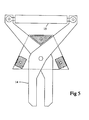
- a shear-type gripper 14 At the free end of the rod 23 is mounted a shear-type gripper 14 with a pertaining sixth hydraulic cylinder 15.
- the shear-type is shown in more details in Fig. 5.
- the shear-type gripper is positioned at a distance from the grip claw 10 and the distance is adjustable by the rod 23 by means of the hydraulic cylinder 25.
- transverse members at fixed positions along the guide beams 2.
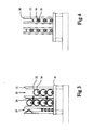
- Two such transverse members are constructed as magazine members 16 and one such magazine member is shown in more details in Fig. 3.
- the magazine member comprises a transverse beam 16 and four vertical U-beams 31 spaced apart in the transverse direction by a distance so that outer drill tubes 33 can be placed in the space between two adjacent U-beams 31.
- two compartments 32 for outer drill tubes each housing a maximum of four outer drill tubes.
- Each outer drill tube encloses an inner drill tube 34 as described in more details below.
- the drill tubes are retained by means of plate springs 17 or spring loaded holders 24 so that they cannot fall out from the magazine at vertical or so called negative drilling when the feed beam 3 is vertical or slopes more than 90° in relation to the horizontal.
- the magazine members 16 are placed at a distance from each other corresponding to the length of the outer drill tubes.
- each magazine member is positioned 0,2 - 0,4 meters from the end of the outer drill tubes, so that the distance between the magazine members 16 is as large as possible.
- the magazine members 16 are preferably welded to the guide beams 2, but it is possible to have one (or several) of the magazine member 16 (the upper) adjustable or replaceable for adoption to drill tubes of different lengths and diameters.
- each inner drill tube is provided with a jointing sleeve 35 comprising screw windings for connection to a lower inner drill tube in the drill hole.
- Said jointing sleeve 35 forms an enlargement of the upper end of each inner drill tube.
- Said spacing member 18 comprises several vertical rods 36 as shown in Fig. 4 spaced apart for engagement below the enlargement of the jointing sleeves 35 for preventing the inner drill tubes to enter inside the outer drill tubes.
- each inner drill tube extends out from or to the left of the outer drill tube as shown in Fig. 1.
- the outer drill tubes are placed between the magazine members 16 and the inner drill tubes are placed inside the outer drill tubes and hang in the space member 18.
- the inner drill tubes are placed manually in the outer drill tubes or the shear-type gripper is used as described more closely below.
- the first outer drill tube and the first inner drill tube are each provided with drill tips, normally with tungsten carbide tips, but other constructions can also be used together with the invention.
- all hydraulic cylinders 5,7,9,12,15 and 25 can be activated.
- the shear-type gripper 14 is adjusted, in its open position, over the first inner drill tube 34, immediately below its jointing sleeve 35 between the space member 18 and the magazine members 16.
- the open grip claw 10 is at the same time positioned over the corresponding outer drill tube 33 and approximately at its longitudinal middle point.
- the boom 8 and the upper part of the pillar are now adjusted and moved against the drill tubes so that the plate 13 will be placed firmly against the outer side of the outer drill tube.
- both the grip claw 10 and the shear-type gripper 14 is activated by means of respective hydraulic cylinders, whereby both the inner drill tube and the outer drill tube are captured in a position parallel with the feed beam 3.
- the captured drill tubes can be moved into the drilling centre position above the feed beam 3 and down through the drill tube guidings 19, 22 at the lower end of the feed beam.
- the drifter 20 By means of the drifter 20, first the inner drill tube is screwed to the adapter, whereupon the shear-type gripper 14 is opened. Then, the outer drill tube is screwed to the adapter, whereupon the grip claw 10 is opened. Both drill tubes are now connected to the adapter. At continued rotation of the adapter, the inner and outer drill tubes are screwed to the upper ends of corresponding drill tubes already placed in the drill hole guided by the drill tube guidings 19, 22.
- Both drill tubes are now connected to the drifter and the drilling starts.
- the drill tubes are screwed off from the adapter by means of the drifter and a drill tube releaser 22 of known construction at the lower end of the feed beam.
- the drifter is moved to its upper position, whereupon a new length of outer and inner drill tubes are screwed on the drill tubes already inside the drill hole and so on.
- an inner drill tube 34 can be placed in position inside an outer drill tube 33 already placed in the magazine space 32 in the following way.
- the inner drill tube is positioned in the space 37 to the left in Fig. 3.
- the cradle 4 is moved to the far right in Fig. 1 and the shear-type gripper is withdrawn as far as possible towards the cradle 4.
- the shear-type gripper will be positioned at the middle of the inner drill tube and one such drill tube is gripped and lifted from the magazine.
- the cradle 4 is moved to the left in Fig.
- the inner drill tubes will be positioned to the left of the mouth of the outer drill tube positioned in the magazine and can be fed inside the outer drill tube by operating the pillar, the boom, the rod 23 and the cradle 4.
- the inner drill tube can of course only be moved inside the outer drill tube to the half length thereof, but the continued movement takes place either with the gravitational force if the feed beam is sloping or by gripping the outer drill tube by the shear-type gripper at a position further out.
- Fig. 6 corresponds to Fig. 1.
- the drill tubes are reversed so that the enlarged jointing sleeve 35 is positioned downwards, to the right in Fig. 6.
- the direction of the shear-type gripper 14 is reversed.
- the spacing member is replaced by a stop member 38 preventing the outer drill tubes 33 to reach the abutment plate 26.
- the inner drill tubes 34 extend through the outer drill tubes and extend beyond the stop member 38 until the abutment plate 26.
- the inner drill tubes 33 can be gripped by the shear-type gripper 14 below the outer drill tubes 33.
- the adapter must be replaced by an alternative adapter, in which the screw windings cooperating with the inner drill tubes are made as inner windings in a hole 39 of the adapter. This construction is more rugged. In all other respects the same construction is used.
- the above constructions can also be further modified.
- One possibility is to provide the pillar 6 with a possibility to rotate around a vertical axis, so that the rod 23 can be adjusted so that it is always parallel with the feed beam.
- an inner drill tube is gripped by the grip claw 10 and placed in position atthe feed beam.
- the inner drill tube is connected to the adapter and screwed to the inner drill tube already in the hole.
- the adapter is disengaged from the inner drill tube and the drifter and adapter is withdrawn to the left as much as possible.
- an outer drill tube positioned in the space 37 is gripped by the grip claw 10 and moved to a position so that it can be placed outside the inner drill tube already present at the feed beam.
- the adapter again engages the upper end of the outer and inner drill tubes and the outer drill tube is at the same time screwed to the outer drill tube already in the hole.
- the drilling machine is now ready for continued work. It is obvious that the drifter and adapter must be moveable the double distance of the length of each of the drill tubes in this case. It is also obvious that an outer drill tube can be mounted before an inner drill tube. The shear-type gripper 14 is not used and can be removed if the equipment is to be used exclusively according to this method.
- valves to the hydraulic cylinders can be operated by a microprocessor in a certain sequence, which corresponds to a normal handling sequence.
- the operator can monitor the operation of the device and can intervene if necessary.
Landscapes
- Engineering & Computer Science (AREA)
- Life Sciences & Earth Sciences (AREA)
- Geology (AREA)
- Mining & Mineral Resources (AREA)
- Physics & Mathematics (AREA)
- Environmental & Geological Engineering (AREA)
- Fluid Mechanics (AREA)
- General Life Sciences & Earth Sciences (AREA)
- Geochemistry & Mineralogy (AREA)
- Mechanical Engineering (AREA)
- Earth Drilling (AREA)
Applications Claiming Priority (2)
| Application Number | Priority Date | Filing Date | Title |
|---|---|---|---|
| SE9201119 | 1992-04-07 | ||
| SE9201119A SE500747C2 (sv) | 1992-04-07 | 1992-04-07 | Utrustning för hantering och magasinering av borrör |
Publications (3)
| Publication Number | Publication Date |
|---|---|
| EP0565502A1 true EP0565502A1 (fr) | 1993-10-13 |
| EP0565502B1 EP0565502B1 (fr) | 1996-10-30 |
| EP0565502B2 EP0565502B2 (fr) | 2000-07-26 |
Family
ID=20385898
Family Applications (1)
| Application Number | Title | Priority Date | Filing Date |
|---|---|---|---|
| EP93850062A Expired - Lifetime EP0565502B2 (fr) | 1992-04-07 | 1993-03-30 | Installation et procédé de manipulation de tiges pour une machine de forage de roche |
Country Status (4)
| Country | Link |
|---|---|
| EP (1) | EP0565502B2 (fr) |
| DE (2) | DE565502T1 (fr) |
| DK (1) | DK0565502T4 (fr) |
| SE (1) | SE500747C2 (fr) |
Cited By (10)
| Publication number | Priority date | Publication date | Assignee | Title |
|---|---|---|---|---|
| EP0685630A3 (fr) * | 1994-06-01 | 1997-04-02 | Klemm Bohrtech | Dispositif de montage pour tige de forage double. |
| GB2312006A (en) * | 1996-03-29 | 1997-10-15 | Charles Machine Works | Pipe handling device |
| EP0860582A1 (fr) * | 1997-02-25 | 1998-08-26 | Hütte & Co. Bohrtechnik Gesellschaft mit beschränkter Haftung | Procédé et appareil pour le forage avec train de tiges composé de doubles tubes |
| US6179065B1 (en) | 1998-09-02 | 2001-01-30 | The Charles Machine Works, Inc. | System and method for automatically controlling a pipe handling system for a horizontal boring machine |
| WO2002016728A1 (fr) * | 2000-08-23 | 2002-02-28 | Techmo Entwicklungs- Und Vertriebs Gmbh | Procede et dispositif pour assembler, en particulier prolonger, un tube ou une tige |
| WO2001051760A3 (fr) * | 2000-01-12 | 2002-03-07 | Charles Machine Works | Systeme destine a automatiquement percer et aleser des trous de sonde |
| DE10104337B4 (de) * | 2001-02-01 | 2006-04-20 | Gta Maschinensysteme Gmbh | Gestängewechseleinrichtung für Horizontalbohrgeräte |
| WO2006061459A1 (fr) * | 2004-12-07 | 2006-06-15 | Sandvik Mining And Construction Oy | Méthode de forage à tubage, unité de forage et dispositif adaptateur |
| DE10341437B4 (de) * | 2003-09-09 | 2012-02-23 | Klemm Bohrtechnik Zweigniederlassung Der Bauer Maschinen Gmbh | Bohrgerät mit Gestängemagazin und Gestängemanipuliervorrichtung |
| WO2020190196A1 (fr) * | 2019-03-21 | 2020-09-24 | Epiroc Rock Drills Aktiebolag | Appareil, procédé et appareil de forage pour installer des tuyaux dans le sol |
Families Citing this family (3)
| Publication number | Priority date | Publication date | Assignee | Title |
|---|---|---|---|---|
| DE10108696B4 (de) * | 2001-02-23 | 2005-10-13 | Deilmann-Haniel Mining Systems Gmbh | Bohrmaschine für das Doppelkopf- und Überlagerungsbohren mit kreisbogenförmigem Gestängemagazin |
| DE502006001190D1 (de) | 2006-03-07 | 2008-09-04 | Klemm Bohrtechnik Gmbh | Vorrichtung zum Beschicken einer Bohreinrichtung und Bohrgerät |
| CA3188439A1 (fr) * | 2020-08-03 | 2022-02-10 | Tomas BUTTAZZONI FONTAINE | Plateforme pour le stockage, le transport et la manipulation de barres de perforation ou sondage de diametres et longueurs differents |
Citations (5)
| Publication number | Priority date | Publication date | Assignee | Title |
|---|---|---|---|---|
| US2730246A (en) * | 1951-11-03 | 1956-01-10 | Exxon Research Engineering Co | Apparatus for handling pipe in a derrick |
| US3734208A (en) * | 1971-08-19 | 1973-05-22 | Bucyrus Erie Co | Well drill transfer mechanism |
| US4102409A (en) * | 1975-12-11 | 1978-07-25 | Atlas Copco Aktiebolag | Rock drilling machine |
| US4117941A (en) * | 1976-04-01 | 1978-10-03 | Golar-Nor Offshore A/S | Device for handling and racking riser pipes and drill pipes |
| US4765401A (en) * | 1986-08-21 | 1988-08-23 | Varco International, Inc. | Apparatus for handling well pipe |
Family Cites Families (1)
| Publication number | Priority date | Publication date | Assignee | Title |
|---|---|---|---|---|
| DE3901664A1 (de) † | 1989-01-20 | 1990-07-26 | Bauer Spezialtiefbau | Verfahren zum ziehen von aussengestaengen |
-
1992
- 1992-04-07 SE SE9201119A patent/SE500747C2/sv not_active IP Right Cessation
-
1993
- 1993-03-30 DE DE1993850062 patent/DE565502T1/de active Pending
- 1993-03-30 DE DE1993605678 patent/DE69305678T3/de not_active Expired - Lifetime
- 1993-03-30 EP EP93850062A patent/EP0565502B2/fr not_active Expired - Lifetime
- 1993-03-30 DK DK93850062T patent/DK0565502T4/da active
Patent Citations (5)
| Publication number | Priority date | Publication date | Assignee | Title |
|---|---|---|---|---|
| US2730246A (en) * | 1951-11-03 | 1956-01-10 | Exxon Research Engineering Co | Apparatus for handling pipe in a derrick |
| US3734208A (en) * | 1971-08-19 | 1973-05-22 | Bucyrus Erie Co | Well drill transfer mechanism |
| US4102409A (en) * | 1975-12-11 | 1978-07-25 | Atlas Copco Aktiebolag | Rock drilling machine |
| US4117941A (en) * | 1976-04-01 | 1978-10-03 | Golar-Nor Offshore A/S | Device for handling and racking riser pipes and drill pipes |
| US4765401A (en) * | 1986-08-21 | 1988-08-23 | Varco International, Inc. | Apparatus for handling well pipe |
Cited By (18)
| Publication number | Priority date | Publication date | Assignee | Title |
|---|---|---|---|---|
| EP0685630A3 (fr) * | 1994-06-01 | 1997-04-02 | Klemm Bohrtech | Dispositif de montage pour tige de forage double. |
| US6085852A (en) * | 1995-02-22 | 2000-07-11 | The Charles Machine Works, Inc. | Pipe handling device |
| GB2312006A (en) * | 1996-03-29 | 1997-10-15 | Charles Machine Works | Pipe handling device |
| DE19712641A1 (de) * | 1996-03-29 | 1997-10-30 | Charles Machine Works | Übergabeeinrichtung für Rohrschüsse |
| GB2312006B (en) * | 1996-03-29 | 1999-10-27 | Charles Machine Works | Pipe handling device |
| DE19712641B4 (de) * | 1996-03-29 | 2007-07-26 | The Charles Machine Works Inc., Perry | Rohrübergabegerät und Verfahren zum Transportieren mehrerer Rohrschüsse |
| EP0860582A1 (fr) * | 1997-02-25 | 1998-08-26 | Hütte & Co. Bohrtechnik Gesellschaft mit beschränkter Haftung | Procédé et appareil pour le forage avec train de tiges composé de doubles tubes |
| US6550547B1 (en) | 1998-09-02 | 2003-04-22 | The Charles Machine Works, Inc. | System and method for automatically controlling a pipe handling system for a horizontal boring machine |
| US6179065B1 (en) | 1998-09-02 | 2001-01-30 | The Charles Machine Works, Inc. | System and method for automatically controlling a pipe handling system for a horizontal boring machine |
| EP0984132A3 (fr) * | 1998-09-02 | 2003-01-08 | The Charles Machine Works Inc | Système et méthode de commande automatique d'un dispositif de maniement de tiges pour une machine de forage horizontal |
| WO2001051760A3 (fr) * | 2000-01-12 | 2002-03-07 | Charles Machine Works | Systeme destine a automatiquement percer et aleser des trous de sonde |
| WO2002016728A1 (fr) * | 2000-08-23 | 2002-02-28 | Techmo Entwicklungs- Und Vertriebs Gmbh | Procede et dispositif pour assembler, en particulier prolonger, un tube ou une tige |
| DE10104337B4 (de) * | 2001-02-01 | 2006-04-20 | Gta Maschinensysteme Gmbh | Gestängewechseleinrichtung für Horizontalbohrgeräte |
| DE10341437B4 (de) * | 2003-09-09 | 2012-02-23 | Klemm Bohrtechnik Zweigniederlassung Der Bauer Maschinen Gmbh | Bohrgerät mit Gestängemagazin und Gestängemanipuliervorrichtung |
| WO2006061459A1 (fr) * | 2004-12-07 | 2006-06-15 | Sandvik Mining And Construction Oy | Méthode de forage à tubage, unité de forage et dispositif adaptateur |
| US7617887B2 (en) | 2004-12-07 | 2009-11-17 | Sandvik Mining And Construction Oy | Method for casing drilling, drilling unit and adapter device |
| AU2005313303B2 (en) * | 2004-12-07 | 2010-06-10 | Sandvik Mining And Construction Oy | Method for casing drilling, drilling unit and adapter device |
| WO2020190196A1 (fr) * | 2019-03-21 | 2020-09-24 | Epiroc Rock Drills Aktiebolag | Appareil, procédé et appareil de forage pour installer des tuyaux dans le sol |
Also Published As
| Publication number | Publication date |
|---|---|
| DK0565502T4 (da) | 2000-09-18 |
| EP0565502B2 (fr) | 2000-07-26 |
| DK0565502T3 (da) | 1997-02-17 |
| SE9201119D0 (sv) | 1992-04-07 |
| SE9201119L (sv) | 1993-10-08 |
| DE565502T1 (de) | 1995-09-28 |
| DE69305678T2 (de) | 1997-03-20 |
| SE500747C2 (sv) | 1994-08-22 |
| DE69305678T3 (de) | 2000-11-16 |
| DE69305678D1 (de) | 1996-12-05 |
| EP0565502B1 (fr) | 1996-10-30 |
Similar Documents
| Publication | Publication Date | Title |
|---|---|---|
| US6615932B2 (en) | Arrangement in rock drilling apparatus | |
| EP0565502B1 (fr) | Installation et procédé de manipulation de tiges pour une machine de forage de roche | |
| US7537424B2 (en) | Apparatus and method for handling pipe sections | |
| AU769454B2 (en) | Drill rod loader | |
| US4051587A (en) | Pile handling apparatus and methods | |
| NO179052B (no) | Apparat for sentrering av en rördel under en topp-drivanordning for en boremaskin | |
| US9540891B2 (en) | Device and method for handling drill string components and drill rig | |
| NO336391B1 (no) | Rørsetteverktøy | |
| NO335929B1 (no) | Fremgangsmåte og anordning for boring med foringsrør | |
| US6164391A (en) | Fixture for the production of bores with single or double rods | |
| CN109236212A (zh) | 用于地下钻孔机械的夹钳装置 | |
| EA029885B1 (ru) | Гидрофицированная мобильная буровая установка | |
| US20210002968A1 (en) | Drilling tool replacement apparatus | |
| EP4248051B1 (fr) | Système de manipulation de tige pour appareil de forage | |
| EP0105299B1 (fr) | Outils de guidage de tubage | |
| US4345493A (en) | Drill rod holding and break-out device | |
| SE529285C2 (sv) | Anordning och metod för att lossa en gängfog vid bergborrning | |
| NO317698B1 (no) | Anordning for mating av bindemateriale | |
| AT411781B (de) | Verfahren und vorrichtung zum zusammenbauen, insbesondere verlängern, eines rohres bzw. gestänges | |
| CN113775294A (zh) | 一种随钻跟进管棚施工装置及施工方法 | |
| AU719261B2 (en) | Blasthole drill and improved method of operation | |
| US4346631A (en) | Well pipe spinning and torqueing apparatus | |
| NO156423B (no) | Roerhaandteringsanordning for forflytting av roer, spesielt boreroer og foringsroer. | |
| JPS60148986A (ja) | ドリルパイプの取り扱い方法およびその機構 | |
| JPH053395U (ja) | 削孔機におけるロツド着脱装置 |
Legal Events
| Date | Code | Title | Description |
|---|---|---|---|
| PUAI | Public reference made under article 153(3) epc to a published international application that has entered the european phase |
Free format text: ORIGINAL CODE: 0009012 |
|
| AK | Designated contracting states |
Kind code of ref document: A1 Designated state(s): DE DK |
|
| 17P | Request for examination filed |
Effective date: 19940412 |
|
| DET | De: translation of patent claims | ||
| 17Q | First examination report despatched |
Effective date: 19950817 |
|
| GRAG | Despatch of communication of intention to grant |
Free format text: ORIGINAL CODE: EPIDOS AGRA |
|
| GRAH | Despatch of communication of intention to grant a patent |
Free format text: ORIGINAL CODE: EPIDOS IGRA |
|
| GRAH | Despatch of communication of intention to grant a patent |
Free format text: ORIGINAL CODE: EPIDOS IGRA |
|
| GRAA | (expected) grant |
Free format text: ORIGINAL CODE: 0009210 |
|
| AK | Designated contracting states |
Kind code of ref document: B1 Designated state(s): DE DK |
|
| REF | Corresponds to: |
Ref document number: 69305678 Country of ref document: DE Date of ref document: 19961205 |
|
| REG | Reference to a national code |
Ref country code: DK Ref legal event code: T3 |
|
| PLBQ | Unpublished change to opponent data |
Free format text: ORIGINAL CODE: EPIDOS OPPO |
|
| PLBI | Opposition filed |
Free format text: ORIGINAL CODE: 0009260 |
|
| 26 | Opposition filed |
Opponent name: DEILMANN-HANIEL GMBH Effective date: 19970724 Opponent name: ING. G. KLEMM BOHRTECHNIK GMBH Effective date: 19970724 |
|
| PLBF | Reply of patent proprietor to notice(s) of opposition |
Free format text: ORIGINAL CODE: EPIDOS OBSO |
|
| PLBF | Reply of patent proprietor to notice(s) of opposition |
Free format text: ORIGINAL CODE: EPIDOS OBSO |
|
| PLBF | Reply of patent proprietor to notice(s) of opposition |
Free format text: ORIGINAL CODE: EPIDOS OBSO |
|
| PLAW | Interlocutory decision in opposition |
Free format text: ORIGINAL CODE: EPIDOS IDOP |
|
| PLAW | Interlocutory decision in opposition |
Free format text: ORIGINAL CODE: EPIDOS IDOP |
|
| PUAH | Patent maintained in amended form |
Free format text: ORIGINAL CODE: 0009272 |
|
| STAA | Information on the status of an ep patent application or granted ep patent |
Free format text: STATUS: PATENT MAINTAINED AS AMENDED |
|
| 27A | Patent maintained in amended form |
Effective date: 20000726 |
|
| AK | Designated contracting states |
Kind code of ref document: B2 Designated state(s): DE DK |
|
| REG | Reference to a national code |
Ref country code: DK Ref legal event code: T4 |
|
| EN | Fr: translation not filed | ||
| PGFP | Annual fee paid to national office [announced via postgrant information from national office to epo] |
Ref country code: DK Payment date: 20120323 Year of fee payment: 20 |
|
| PGFP | Annual fee paid to national office [announced via postgrant information from national office to epo] |
Ref country code: DE Payment date: 20120322 Year of fee payment: 20 |
|
| REG | Reference to a national code |
Ref country code: DK Ref legal event code: EUP |
|
| REG | Reference to a national code |
Ref country code: DE Ref legal event code: R071 Ref document number: 69305678 Country of ref document: DE |
|
| PG25 | Lapsed in a contracting state [announced via postgrant information from national office to epo] |
Ref country code: DE Free format text: LAPSE BECAUSE OF EXPIRATION OF PROTECTION Effective date: 20130403 |