EP0565509B1 - Leimpresse - Google Patents
Leimpresse Download PDFInfo
- Publication number
- EP0565509B1 EP0565509B1 EP93850077A EP93850077A EP0565509B1 EP 0565509 B1 EP0565509 B1 EP 0565509B1 EP 93850077 A EP93850077 A EP 93850077A EP 93850077 A EP93850077 A EP 93850077A EP 0565509 B1 EP0565509 B1 EP 0565509B1
- Authority
- EP
- European Patent Office
- Prior art keywords
- applicator
- catches
- size press
- press
- rolls
- Prior art date
- Legal status (The legal status is an assumption and is not a legal conclusion. Google has not performed a legal analysis and makes no representation as to the accuracy of the status listed.)
- Expired - Lifetime
Links
- 239000011248 coating agent Substances 0.000 claims abstract description 27
- 238000000576 coating method Methods 0.000 claims abstract description 20
- 230000006835 compression Effects 0.000 claims description 3
- 238000007906 compression Methods 0.000 claims description 3
- 238000010276 construction Methods 0.000 description 6
- 230000001627 detrimental effect Effects 0.000 description 2
- 230000035939 shock Effects 0.000 description 2
- 239000006096 absorbing agent Substances 0.000 description 1
- 238000010521 absorption reaction Methods 0.000 description 1
- 238000009826 distribution Methods 0.000 description 1
- 239000000049 pigment Substances 0.000 description 1
- 238000009827 uniform distribution Methods 0.000 description 1
Images
Classifications
-
- D—TEXTILES; PAPER
- D21—PAPER-MAKING; PRODUCTION OF CELLULOSE
- D21H—PULP COMPOSITIONS; PREPARATION THEREOF NOT COVERED BY SUBCLASSES D21C OR D21D; IMPREGNATING OR COATING OF PAPER; TREATMENT OF FINISHED PAPER NOT COVERED BY CLASS B31 OR SUBCLASS D21G; PAPER NOT OTHERWISE PROVIDED FOR
- D21H23/00—Processes or apparatus for adding material to the pulp or to the paper
- D21H23/02—Processes or apparatus for adding material to the pulp or to the paper characterised by the manner in which substances are added
- D21H23/22—Addition to the formed paper
- D21H23/52—Addition to the formed paper by contacting paper with a device carrying the material
- D21H23/56—Rolls
- D21H23/58—Details thereof, e.g. surface characteristics, peripheral speed
Definitions
- the invention concerns a size press comprising a nip formed by press rolls, through which nip the paper or board web is passed and in which size press the first press roll is mounted by means of bearings permanently on the frame of the size press, whereas the other press roll is mounted on the frame of the size press by means of its bearings as displaceable by the intermediate of loading arms or equivalent, and in which size press the press rolls are provided with coating devices for the spreading of films of coating agent onto the faces of said rolls, said coating devices being mounted on applicator beams transverse to the machine direction, which applicator beams are supported pivotally on the frame of the size press or on the loading arms of the displaceable roll and which applicator beams are provided with pivot cylinders, by whose means the applicator beams can be opened and closed in relation to the rolls corresponding to them, and which applicator beams are provided with catches, which are arranged to be supported directly or indirectly on the bearings of the rolls that correspond to them when said applicator beams are being closed by means of the
- the size press comprises a pair of rolls which form a nip, the paper or board web being passed through said nip.
- the coating agent such as a size or pigment coating
- the coating agent is applied as a film onto the faces of the rolls by means of application devices, and in the roll nip the coating agent is transferred onto the web to be coated.
- one roll in the pair of rolls is mounted on the frame of the size press permanently by means of bearings, whereas the other roll is mounted on the frame displaceably, e.g., by means of pivot arms, which permit opening of the nip and loading of the rolls against one another so as to produce the desired nip pressure.
- the size-press construction described above involves a problem, which is manifested in particular in connection with replacement of the rolls.
- the new roll is not always positioned optimally on the frame of the size press, but it remains slightly inclined.
- the displaceable roll is positioned in a way corresponding to the fixed roll to produce a uniform nip pressure.
- the displaceable roll is also positioned as inclined in a way corresponding to the fixed roll.
- the application devices of the rolls are normally mounted on an applicator beam parallel to the faces of the rolls, which beam is linked pivotally on the frame of the size press or on the loading arm of the displaceable roll.
- the applicator beam is normally provided with pivot cylinders, by whose means the beam and the coating device mounted on the beam are "closed” against the corresponding roll.
- the construction of the applicator beam is very rigid, for which reason it cannot always be positioned, by means of its pivot cylinders, in the way corresponding to the positions of the rolls.
- An applicator beam is, as a rule, provided with mechanical catches, which, when the beam is closed, rest against catch faces formed on the bearing housings of the roll. If the roll has been positioned in a highly inclined position, on closing of the beam a situation may arise in which the catch placed at one side of the beam only reaches contact with the bearing housing of the roll, whereas a gap remains between the catch placed at the opposite side and the catch face formed on the bearing housing. Even if the coating member of the coating device could be placed correctly against the roll face, by means of its loading hose, the pivot cylinders of the applicator beam usually produce an error in the nip pressure, which error is increased linearly in the transverse direction of the machine. This has again had a highly detrimental effect on the coating result.
- Hydraulic catches have also been applied in applicator beams of size presses. In their simplest form, they consist of a hydraulic cylinder whose length can be adjusted, i.e. of a "jack", by whose means, by adjusting its length, both ends of the applicator beam can be made to rest against the catch faces formed on the bearing housings of the roll.
- the drawbacks related to such a solution are, however, similar to those of the mechanical catches described above, i.e. the regulation is difficult, because the two catches must be adjusted separately.
- the support forces of both of the catches would have to be adjusted equal in order that the pivot cylinders of the applicator beam should not produce an error in the nip pressure.
- More "advanced" hydraulic catches always involve complicated control and regulation circuits, which are also expensive. Also, hydraulic systems always involve a risk of leakage.
- the object of the present invention is to provide a solution by whose means the above drawbacks related to the prior art are avoided and by whose means, therefore, an improved coating result is obtained.
- the invention is mainly characterized in that at least one of the applicator beams of the size press is provided with catches placed at each end of the applicator beam and positioned in accordance with the position of the applicator beam, said catches being attached to the applicator beam by means of articulated joints and said catches being interconnected mechanically.
- the load of the size nip in the size press i.e. the nip pressure
- the load of the size nip in the size press i.e. the nip pressure
- the thickness of the layer of coating agent on the paper or board web to be coated can be made as desired across the width of the web.
- a further advantage of the invention is low cost and simplicity.
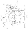
- Figure 1 is a fully schematic side view of a size press.
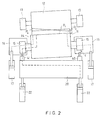
- Figure 2 is a schematic top view of a size press showing, with exaggeration, inclined positioning of the rolls and the resulting error in the nip pressure.
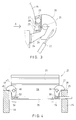
- Figure 3 is an enlarged detail of Fig. 1, illustrating the construction of the catches on the applicator beam.
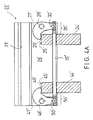
- Figure 4 corresponds to Fig. 3, viewed in the direction A.
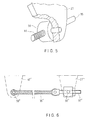
- Figure 5 is a further enlarged detail of Fig. 4.
- Figure 6 shows a construction alternative to that shown in Fig. 4.
- Fig. 1 is a schematic illustration of a size press, which is denoted generally with the reference numeral 10.
- the press rolls 12,14 in the size press 10 form a nip N with one another, through which nip the paper or board web W is passed.
- the web W is passed into the nip N over a guide roll 19.
- the bearing 13 of the first press roll 12 is mounted on the frame 11 of the size press permanently, and, in a corresponding way, the bearing 15 of the second press roll 14 is mounted on a loading arm 16, which is fitted on the frame 11 of the size press pivotally by means of an articulated joint 18.
- loading cylinders are fitted 17, by whose means the nip N can be opened and closed and by whose means the loading pressure between the rolls 12,14, i.e. the nip pressure, can be adjusted to the desired level.
- Each roll 12,14 in the size press 10 is provided with a coating device 23,23a of its own, by means of which coating device a film of coating agent is applied to the face of the respective roll 12,14, said film being transferred onto the web W in the roll nip N.
- Each of the coating devices 23,23a is mounted on an applicator beam 20,20a transverse to the machine direction.
- the applicator beam 20a of the first press roll 12 is mounted pivotally, by means of an articulated joint 21a, on holders 24a fixed to the frame 11 of the size press, and further, between said applicator beam 20a and the frame 11 of the size press, pivot cylinders 22a are fitted, by whose means the applicator beam 20a can be opened and closed in relation to the roll 12.
- the coating device 23 of the second press roll 14 is mounted on an applicator beam 20 transverse to the machine direction, which beam is, by means of an articulated joint 21, mounted pivotally on holders 24 fixed to the loading arm 16. Between the applicator beam 20 and the loading arm 16, pivot cylinders 22 are fitted, by whose means the applicator beam 20 can be opened and closed in relation to the second press roll 14.
- the applicator beam 20 cannot be positioned in a similar way diagonally when it is closed by means of the pivot cylinders 22. This comes in particular from the high rigidity of the applicator beam 20. If the applicator beam 20 is provided with conventional mechanical catches 40,41, when the beam 20 is closed, one catch 41 is loaded against the catch face formed on the bearing 15 of the press roll, whereas, in the worst case, a gap c remains between the catch 40 placed at the opposite side of the machine and the catch face on the bearing 15.
- the force produced by the pivot cylinder 22 at the end next to the gap C of the applicator beam 20 is transferred as a torque along the beam 20 to the other end of the beam and from there further to the loading arm 16, thus increasing the nip force by the amount P2.
- the force produced by the pivot cylinder 22 lowers the nip force by the amount P3.
- Fig. 2 attempts have been made to illustrate the transfer of the forces by the dashed lines. Again, this has the consequence that the pressure distribution p2 produced by the pivot cylinders 22 of the applicator beam 20 in the nip N is not even, but, for example, linearly changing, as is illustrated in Fig. 2.
- the nip pressure is, at one edge of the nip N, substantially higher than at the opposite edge. This has a considerably detrimental effect on the coating result.
- Figs. 3 and 4 illustrate the support arrangement of the applicator beam 20 of the displaceable roll 14, i.e. of the roll mounted on the loading arm 16, of the size press, but a fully equivalent arrangement can also be accomplished on the applicator beam 20a at the side of the fixed roll 12.
- the applicator beam 20 is mounted pivotally, by means of the articulated joint 21, on the holders 24,44.
- the applicator beam 20 and the coating device 23 fitted on it can pivoted between the coating position, i.e. the closed position, shown in Fig. 3 and the open position.
- lever-shaped catches 27,47 in accordance with the invention are fitted, which are linked to said wall 26 of the applicator beam by means of articulated joints 28,48 so that said lever-shaped catches 27,47 can pivot around said articulated joints 28,48.
- each lever-shaped catch 27,47 At the first end of each lever-shaped catch 27,47, a cam 29,49 has been formed, which rests against the support 25,45 fitted on each holder 24,44 when the applicator beam 20 is in the closed position.
- the position of said supports 25,45 is fixed in relation to the bearing 15 of the roll 14.
- a connecting link 30,50 is fitted, at the second end of each catch 27,47, i.e. at the opposite side of the articulated joint 28,48 with respect to the cam 29,49, by a connecting link 30,50 is fitted, by whose means the catches 27,47 are interconnected by means of a pulling member 35, which is a rigid connecting rod in the embodiment of Fig. 4.
- a pulling member 35 which is a rigid connecting rod in the embodiment of Fig. 4.
- the construction of the applicator beam 20 is very rigid with respect to rotation.
- it is easy to end up in a situation as shown in Fig. 2, in which the contact is lost between the machine frame and one catch of the applicator beam 20.
- it is, however, possible to equalize the support forces produced by the pivot cylinders 22, because the catches 27,47 placed at each end of the applicator beam 20 are interconnected by means of articulated joints in the way in accordance with the invention. Then, if the roll 14 has been placed diagonally as shown in Fig. 2, when the application beam 20 is being closed, a situation arises in which the cam 49 of the second catch 47 meets the support 45 on the holder 44 first.
- both of the catches 27,47 are in contact with the supports 25,45 with a substantially equal support force, in which case the support forces produced by the pivot cylinders 22 are equal at each end of the applicator beam 20.
- the beam receives its adjusted position in relation to the roll 14.
- the kinetic energy of the pivoting movement of the applicator beam 20 is absorbed by means of shock absorbers, but it is also possible to arrange the shock absorption on the connecting rod 35 itself.
- Fig. 4A shows an alternative to the solution of Fig. 4.
- the applicator beam is denoted with the reference numeral 20' and the coating device with the numeral 23'.
- the lever-shaped catches 27',47' are mounted, as compared with the situation of Fig. 4, as mirror images in relation to the vertical axes running through the articulated joints 28',48', in which case the intermediate member 35' acts as the member that receives the compression force.
- the reference numerals 24',44' refer to the holders, and the reference numerals 30',50' to the connecting links.
- the threaded parts of the intermediate member 35' are denoted with the references 36',56', the cams of the catches 27',47' with the references 29',49', and the supports on the holders 24',44' with the references 25',45'.
- the reference 26' refers to the wall of the applicator beam 20'.
- the member 35' that receives the compression force can be substituted for by a pulling member, such as a wire (not shown), which interconnects the connecting links (30',50') and passes, e.g., over reversing pulleys, which are placed outside the connecting links 30',50' in the direction of width of the applicator beam 20'.
- a pulling member such as a wire (not shown), which interconnects the connecting links (30',50') and passes, e.g., over reversing pulleys, which are placed outside the connecting links 30',50' in the direction of width of the applicator beam 20'.
- Fig. 6 shows a further embodiment alternative to the solution shown in Fig. 4.
- the dashed lines and the references 27'' and 47'' represent the catch ends next to the connecting links.
- the connecting links are denoted in the figure with the references 30'' and 50''.
- the solution as shown in Fig. 6 differs from Fig. 4 in the respect that, in Fig. 6, the connecting rod 35 as shown in Fig. 4 has been substituted for by a wire 35'' or by an equivalent flexible pulling member.
- a length-adjusting device 37'' has been fitted, by whose means it is possible to carry out necessary regulation of the pre-stressing.
- the solution of Fig. 6 is similar to the embodiment shown in Fig. 4.
Landscapes
- Coating Apparatus (AREA)
- Diaphragms For Electromechanical Transducers (AREA)
- Basic Packing Technique (AREA)
Claims (8)
- Eine Leimpresse, die einen Spalt (N) aufweist, der durch Presswalzen (12,14) ausgebildet wird, wobei eine Papier- oder Pappenbahn (W) durch den Spalt geführt wird, und wobei in der Leimpresse die erste Presswalze (12) durch Lager (13) ruhend auf dem Rahmen (11) der Leimpresse befestigt ist, währenddessen die andere Presswalze (14) auf dem Rahmen (11) der Leimpresse durch ihre Lager (15) durch Belastungsarme (16) oder dergleichen versetzbar befestigt ist, und wodurch bei der Leimpresse die Presswalzen (12,14) mit Auftragsvorrichtungen (23,23a) zum Verteilen dünner Filmschichten eines Beschichtungsmittels auf die Flächen der Walzen versehen sind, wobei die Auftragsvorrichtungen (23,23a) auf Applizierträgern (20,20a) befestigt sind, die parallel zu den Walzenflächen liegen, wobei die Applizierträger schwenkbar auf dem Rahmen (11) der Leimpresse oder auf den Belastungsarmen (16) der versetzbaren Walze (14) gelagert sind, und wobei die Applizierträger mit Schwenkzylindern (22,22a) versehen sind, durch die die Applizierträger (20,20a) im Verhältnis zu den diesen entsprechenden Walzen (20,14) geöffnet und geschlossen werden können, und wobei die Applizierträger (20,20a) mit Anschlägen (27,47) versehen sind, die angeordnet sind, um direkt oder indirekt auf den Lagern (13,15) der ihnen jeweils entsprechenden Walzen (12,14) gelagert zu werden, wenn die Applizierträger durch die Schwenkzylinder (22,22a) geschlossen werden, dadurch gekennzeichnet, daß zumindest einer der Applizierträger (20) der Leimpresse mit Anschlägen (27,47) versehen ist, die an einem jeden Ende des Applizierträgers (20) angeordnet sind und in Übereinstimmung mit der Position des Applizierträgers (20) positioniert sind, wobei die Anschläge durch Gelenkverbindungen an dem Applizierträger (20) befestigt sind und die Anschläge mechanisch miteinander verbunden sind.
- Eine Leimpresse gemäß Anspruch 1, dadurch gekennzeichnet, daß die Anschläge (27,47) Hebel aufweisen, die mit dem Applizierträger (20) durch eine Gelenkverbindung (28,48) verbunden sind, wobei an einem Ende der Hebel eine Nocke (29,49) ausgebildet ist, die während dem Schließen des Applizierträgers (20) so angeordnet ist, um gegen einen Träger (25,45), der in einer steifen Verbindung mit dem Lager (15) der Walze (14) steht, gelagert zu werden, und wobei die Hebel bezüglich der Gelenkverbindungen (28,48) an deren gegenüberliegenden Ende durch ein Zwischenstück (35,35',35'') miteinander verbunden sind.
- Eine Leimpresse gemäß Anspruch 1 oder 2, dadurch gekennzeichnet, daß das Zwischenstück (35,35',35'') durch Verbindungsgelenke (30,50) mit den hebelförmigen Anschlägen (27,47) verbunden ist, deren Schwenkwellen parallel zu den Gelenkverbindungen (28,48) der Anschläge (27,47) sind und eine viereckige Gelenkverbindung bilden.
- Eine Leimpresse gemäß einem der vorhergehenden Ansprüche, dadurch gekennzeichnet, daß das Zwischenstück (35,35',35'') so einstellbar ist, daß es durch die Einstellung des Zwischenstücks möglich ist, die relative Distanz zwischen den Verbindungsgelenken (30,50) der hebelförmigen Anschläge (27,47) zu ändern.
- Eine Leimpresse gemäß einem der vorhergehenden Ansprüche, dadurch gekennzeichnet, daß das Zwischenstück ein Verbindungszapfen (35,35') ist, der in den Bereichen der Verbindungsgelenke (30,50,30',50') der Anschläge mit Gewindeabschnitten (36,56,36',56') versehen ist, so daß die ersten und zweiten Gewindeabschnitte entgegengesetzte Schraubrichtungen haben, und daß in einer entsprechenden Art und Weise die Verbindungsgelenke, (30,50,30',50') mit Bohrungen mit Innengewinden versehen sind, deren Axialrichtung senkrecht zu den Schwenkwellen der Verbindungsgelenke (30,50,30',50') sind, wodurch, wenn der Verbindungszapfen (35,35') in eine Richtung gedreht wird, die Verbindungsgelenke (30,50,30',50') der Anschläge (27,47, 27',47') so angeordnet werden, um sich einander zu nähern, und um sich voneinander weg zu bewegen, wenn der Zapfen in die entgegengesetzte Richtung gedreht wird.
- Eine Leimpresse gemäß einem der vorhergehenden Ansprüche, dadurch gekennzeichnet, daß das Zwischenstück ein Zugbauteil (35,35'') ist.
- Eine Leimpresse gemäß einem der vorhergehenden Ansprüche 1 bis 5, dadurch gekennzeichnet, daß das Zwischenstück ein Bauteil (35') ist, das Druckkraft aufnimmt.
- Eine Leimpresse gemäß einem der Ansprüche 1 bis 4 oder 6, dadurch gekennzeichnet, daß das Zugbauteil ein Draht (35'') oder ein vergleichbares flexibles Bauteil ist, das mit einer Längeneinstellvorrichtung (37'') versehen ist, damit die relative Distanz zwischen den Verbindungsgelenken (30'',50'') der Anschläge geändert werden kann.
Applications Claiming Priority (2)
| Application Number | Priority Date | Filing Date | Title |
|---|---|---|---|
| FI921631A FI92423C (fi) | 1992-04-10 | 1992-04-10 | Laite liimapuristimessa |
| FI921631 | 1992-04-10 |
Publications (2)
| Publication Number | Publication Date |
|---|---|
| EP0565509A1 EP0565509A1 (de) | 1993-10-13 |
| EP0565509B1 true EP0565509B1 (de) | 1994-12-21 |
Family
ID=8535092
Family Applications (1)
| Application Number | Title | Priority Date | Filing Date |
|---|---|---|---|
| EP93850077A Expired - Lifetime EP0565509B1 (de) | 1992-04-10 | 1993-04-07 | Leimpresse |
Country Status (6)
| Country | Link |
|---|---|
| US (1) | US5401315A (de) |
| EP (1) | EP0565509B1 (de) |
| AT (1) | ATE116024T1 (de) |
| CA (1) | CA2093698A1 (de) |
| DE (1) | DE69300034T2 (de) |
| FI (1) | FI92423C (de) |
Families Citing this family (7)
| Publication number | Priority date | Publication date | Assignee | Title |
|---|---|---|---|---|
| FI111134B (fi) * | 1997-03-13 | 2003-06-13 | Metso Paper Inc | Menetelmä ja sovitelma filminsiirtopuristimen telojen värähtelyjen estämiseksi |
| US5782976A (en) * | 1997-06-27 | 1998-07-21 | Westvaco Corporation | Continuous coater blade |
| US6649262B2 (en) | 2001-07-06 | 2003-11-18 | Kimberly-Clark Worldwide, Inc. | Wet roll having uniform composition distribution |
| US7101587B2 (en) | 2001-07-06 | 2006-09-05 | Kimberly-Clark Worldwide, Inc. | Method for wetting and winding a substrate |
| US20030113458A1 (en) * | 2001-12-18 | 2003-06-19 | Kimberly Clark Worldwide, Inc. | Method for increasing absorption rate of aqueous solution into a basesheet |
| US6866220B2 (en) | 2001-12-21 | 2005-03-15 | Kimberly-Clark Worldwide, Inc. | Continuous motion coreless roll winder |
| US7086500B2 (en) * | 2003-10-31 | 2006-08-08 | Wing Enterprises, Inc. | Extensible, self locking platform and method of using same |
Family Cites Families (6)
| Publication number | Priority date | Publication date | Assignee | Title |
|---|---|---|---|---|
| US2273021A (en) * | 1940-02-28 | 1942-02-17 | American Can Co | Adhesive applying machine |
| US3487813A (en) * | 1963-10-15 | 1970-01-06 | Lester M Hill | Flooded nip coater pan assembly |
| JPS59142150A (ja) * | 1983-02-03 | 1984-08-15 | Komori Printing Mach Co Ltd | 印刷物ニス塗り装置 |
| US4495886A (en) * | 1983-09-26 | 1985-01-29 | The Black Clawson Company | Precision roll coater |
| FI85895C (fi) * | 1988-11-18 | 1992-06-10 | Valmet Paper Machinery Inc | Foerfarande foer kompensation av boejningen hos en schaber och boejningskompenserad schaber. |
| DE4102022C2 (de) * | 1990-06-18 | 1995-01-12 | Eti Tec Maschinenbau | An eine Leimwalze anschwenkbarer, geteilter Leimschaber in einer Etikettiermaschine für Behälter, insbesondere Flaschen |
-
1992
- 1992-04-10 FI FI921631A patent/FI92423C/fi active
-
1993
- 1993-04-07 DE DE69300034T patent/DE69300034T2/de not_active Expired - Fee Related
- 1993-04-07 AT AT93850077T patent/ATE116024T1/de not_active IP Right Cessation
- 1993-04-07 EP EP93850077A patent/EP0565509B1/de not_active Expired - Lifetime
- 1993-04-08 CA CA002093698A patent/CA2093698A1/en not_active Abandoned
- 1993-04-09 US US08/045,637 patent/US5401315A/en not_active Expired - Fee Related
Also Published As
| Publication number | Publication date |
|---|---|
| DE69300034D1 (de) | 1995-02-02 |
| FI92423B (fi) | 1994-07-29 |
| FI92423C (fi) | 1994-11-10 |
| FI921631L (fi) | 1993-10-11 |
| FI921631A0 (fi) | 1992-04-10 |
| CA2093698A1 (en) | 1993-10-11 |
| ATE116024T1 (de) | 1995-01-15 |
| US5401315A (en) | 1995-03-28 |
| EP0565509A1 (de) | 1993-10-13 |
| DE69300034T2 (de) | 1995-05-11 |
Similar Documents
| Publication | Publication Date | Title |
|---|---|---|
| EP0679204B2 (de) | Verfahren zum kalandrieren einer papier- oder ähnlichen materialbahn und kalander zur durchführung des verfahrens | |
| US6419794B2 (en) | Method and apparatus for damping contact oscillations of rotating rolls | |
| US5038678A (en) | Calender, in particular a supercalender with multiple relief devices | |
| KR940011914B1 (ko) | 로울 | |
| EP0565509A1 (de) | Leimpresse | |
| CA2093675C (en) | Applicator beam in a size press | |
| CA2052782C (en) | Device for proportioning of a coating agent onto a moving base | |
| CA1215535A (en) | Precision roll coater | |
| FI119068B (fi) | Menetelmä kalanterissa ja monitelakalanteri sekä menetelmä monitelakalanterin kalanteritelan laakerin kuormittamiseksi ja monitelakalanteri | |
| FI75218B (fi) | Foerfarande vid boejningsreglerad vals och valsanordning foer tillaempning av foerfarandet. | |
| EP0561757B1 (de) | Halterung für ein Gestell für eine Stabbeschichtungsvorrichtung oder einer Streichrakel | |
| FI91300B (fi) | Laite liimapuristimessa | |
| FI92619B (fi) | Pintaliimausyksikkö liimapuristinta varten | |
| GB2054758A (en) | Improvements in or relating to a roll mounting | |
| FI119335B (fi) | Monitelakalanteri | |
| FI80772B (fi) | Foerfarande vid en boejningsreglerad vals och en boejningsreglerad vals. | |
| WO2001021889A1 (en) | Method and arrangement for control of rolls in a calender | |
| FI97401C (fi) | Kalanteri |
Legal Events
| Date | Code | Title | Description |
|---|---|---|---|
| PUAI | Public reference made under article 153(3) epc to a published international application that has entered the european phase |
Free format text: ORIGINAL CODE: 0009012 |
|
| AK | Designated contracting states |
Kind code of ref document: A1 Designated state(s): AT CH DE FR GB IT LI SE |
|
| 17P | Request for examination filed |
Effective date: 19931019 |
|
| 17Q | First examination report despatched |
Effective date: 19940216 |
|
| GRAA | (expected) grant |
Free format text: ORIGINAL CODE: 0009210 |
|
| AK | Designated contracting states |
Kind code of ref document: B1 Designated state(s): AT CH DE FR GB IT LI SE |
|
| REF | Corresponds to: |
Ref document number: 116024 Country of ref document: AT Date of ref document: 19950115 Kind code of ref document: T |
|
| EAL | Se: european patent in force in sweden |
Ref document number: 93850077.4 |
|
| REF | Corresponds to: |
Ref document number: 69300034 Country of ref document: DE Date of ref document: 19950202 |
|
| ITF | It: translation for a ep patent filed | ||
| ET | Fr: translation filed | ||
| PLBE | No opposition filed within time limit |
Free format text: ORIGINAL CODE: 0009261 |
|
| STAA | Information on the status of an ep patent application or granted ep patent |
Free format text: STATUS: NO OPPOSITION FILED WITHIN TIME LIMIT |
|
| 26N | No opposition filed | ||
| REG | Reference to a national code |
Ref country code: GB Ref legal event code: IF02 |
|
| PGFP | Annual fee paid to national office [announced via postgrant information from national office to epo] |
Ref country code: CH Payment date: 20020319 Year of fee payment: 10 |
|
| PGFP | Annual fee paid to national office [announced via postgrant information from national office to epo] |
Ref country code: SE Payment date: 20020327 Year of fee payment: 10 |
|
| PGFP | Annual fee paid to national office [announced via postgrant information from national office to epo] |
Ref country code: AT Payment date: 20020328 Year of fee payment: 10 |
|
| PGFP | Annual fee paid to national office [announced via postgrant information from national office to epo] |
Ref country code: GB Payment date: 20020402 Year of fee payment: 10 |
|
| PGFP | Annual fee paid to national office [announced via postgrant information from national office to epo] |
Ref country code: FR Payment date: 20020416 Year of fee payment: 10 |
|
| PGFP | Annual fee paid to national office [announced via postgrant information from national office to epo] |
Ref country code: DE Payment date: 20020418 Year of fee payment: 10 |
|
| PG25 | Lapsed in a contracting state [announced via postgrant information from national office to epo] |
Ref country code: GB Free format text: LAPSE BECAUSE OF NON-PAYMENT OF DUE FEES Effective date: 20030407 Ref country code: AT Free format text: LAPSE BECAUSE OF NON-PAYMENT OF DUE FEES Effective date: 20030407 |
|
| PG25 | Lapsed in a contracting state [announced via postgrant information from national office to epo] |
Ref country code: SE Free format text: LAPSE BECAUSE OF NON-PAYMENT OF DUE FEES Effective date: 20030408 |
|
| PG25 | Lapsed in a contracting state [announced via postgrant information from national office to epo] |
Ref country code: LI Free format text: LAPSE BECAUSE OF NON-PAYMENT OF DUE FEES Effective date: 20030430 Ref country code: CH Free format text: LAPSE BECAUSE OF NON-PAYMENT OF DUE FEES Effective date: 20030430 |
|
| PG25 | Lapsed in a contracting state [announced via postgrant information from national office to epo] |
Ref country code: DE Free format text: LAPSE BECAUSE OF NON-PAYMENT OF DUE FEES Effective date: 20031101 |
|
| GBPC | Gb: european patent ceased through non-payment of renewal fee |
Effective date: 20030407 |
|
| EUG | Se: european patent has lapsed | ||
| REG | Reference to a national code |
Ref country code: CH Ref legal event code: PL |
|
| PG25 | Lapsed in a contracting state [announced via postgrant information from national office to epo] |
Ref country code: FR Free format text: LAPSE BECAUSE OF NON-PAYMENT OF DUE FEES Effective date: 20031231 |
|
| REG | Reference to a national code |
Ref country code: FR Ref legal event code: ST |
|
| PG25 | Lapsed in a contracting state [announced via postgrant information from national office to epo] |
Ref country code: IT Free format text: LAPSE BECAUSE OF NON-PAYMENT OF DUE FEES;WARNING: LAPSES OF ITALIAN PATENTS WITH EFFECTIVE DATE BEFORE 2007 MAY HAVE OCCURRED AT ANY TIME BEFORE 2007. THE CORRECT EFFECTIVE DATE MAY BE DIFFERENT FROM THE ONE RECORDED. Effective date: 20050407 |