EP0565561B1 - Machine de decoupage de carreaux - Google Patents
Machine de decoupage de carreaux Download PDFInfo
- Publication number
- EP0565561B1 EP0565561B1 EP92901684A EP92901684A EP0565561B1 EP 0565561 B1 EP0565561 B1 EP 0565561B1 EP 92901684 A EP92901684 A EP 92901684A EP 92901684 A EP92901684 A EP 92901684A EP 0565561 B1 EP0565561 B1 EP 0565561B1
- Authority
- EP
- European Patent Office
- Prior art keywords
- scoring
- tile
- cutting
- machine
- pressers
- Prior art date
- Legal status (The legal status is an assumption and is not a legal conclusion. Google has not performed a legal analysis and makes no representation as to the accuracy of the status listed.)
- Expired - Lifetime
Links
- 238000005520 cutting process Methods 0.000 title claims abstract description 82
- 230000000284 resting effect Effects 0.000 claims abstract description 8
- 238000003825 pressing Methods 0.000 claims abstract description 5
- 230000000295 complement effect Effects 0.000 claims abstract description 3
- 230000000694 effects Effects 0.000 claims description 9
- 239000000725 suspension Substances 0.000 claims description 5
- 230000004807 localization Effects 0.000 claims description 4
- 239000006096 absorbing agent Substances 0.000 claims description 2
- 230000035939 shock Effects 0.000 claims description 2
- 238000000034 method Methods 0.000 claims 5
- 230000006870 function Effects 0.000 description 4
- 239000000463 material Substances 0.000 description 3
- 230000007547 defect Effects 0.000 description 2
- 229910052571 earthenware Inorganic materials 0.000 description 2
- 238000012797 qualification Methods 0.000 description 2
- 230000003313 weakening effect Effects 0.000 description 2
- XAGFODPZIPBFFR-UHFFFAOYSA-N aluminium Chemical compound [Al] XAGFODPZIPBFFR-UHFFFAOYSA-N 0.000 description 1
- 229910052782 aluminium Inorganic materials 0.000 description 1
- 239000004411 aluminium Substances 0.000 description 1
- 238000005452 bending Methods 0.000 description 1
- 239000011248 coating agent Substances 0.000 description 1
- 238000000576 coating method Methods 0.000 description 1
- 230000001143 conditioned effect Effects 0.000 description 1
- 230000003750 conditioning effect Effects 0.000 description 1
- 239000011521 glass Substances 0.000 description 1
- 230000008447 perception Effects 0.000 description 1
Images


Classifications
-
- B—PERFORMING OPERATIONS; TRANSPORTING
- B28—WORKING CEMENT, CLAY, OR STONE
- B28D—WORKING STONE OR STONE-LIKE MATERIALS
- B28D7/00—Accessories specially adapted for use with machines or devices of the preceding groups
- B28D7/04—Accessories specially adapted for use with machines or devices of the preceding groups for supporting or holding work or conveying or discharging work
- B28D7/043—Accessories specially adapted for use with machines or devices of the preceding groups for supporting or holding work or conveying or discharging work the supporting or holding device being angularly adjustable
-
- B—PERFORMING OPERATIONS; TRANSPORTING
- B28—WORKING CEMENT, CLAY, OR STONE
- B28D—WORKING STONE OR STONE-LIKE MATERIALS
- B28D1/00—Working stone or stone-like materials, e.g. brick, concrete or glass, not provided for elsewhere; Machines, devices, tools therefor
- B28D1/22—Working stone or stone-like materials, e.g. brick, concrete or glass, not provided for elsewhere; Machines, devices, tools therefor by cutting, e.g. incising
- B28D1/225—Working stone or stone-like materials, e.g. brick, concrete or glass, not provided for elsewhere; Machines, devices, tools therefor by cutting, e.g. incising for scoring or breaking, e.g. tiles
Definitions
- the present invention relates to a series of manual, professional, middlelarge machines for cutting very hard tiles, even of the monobaked kind, with a thick glass-like covering and/or heterogeneous structure, whose functionality, productivity and accuracy of cutting is the goal of an integrated collection of numerous original combinations of components and subcomponents, only partially known, characterized also for their dimensions and proportions.
- the basis of the tile cutting art, for cutting a tile P, substantially without material removal, is the provision of a scoring groove I, of deepness i, i.e., for weakening the cross section S, at a vertical plane, corresponding to the cutting T to be made and then stressing, by a force F, contemporarily, mutually, the two parts A and B of tile P, siding the scoring groove I, in at least one point 66, respect at least one point 33 of reaction, coincident with the cutting plane T, i.e., the plane of provision of scoring groove I.
- the machines for cutting tiles do not comply with these requirements. While the tiles - mainly used as wall coating - were of the kind with soft body and a thin layer of glass like material as covering, every kind of cutting machine employed suited well the cutting purpose and the wrong cuttings were mainly to be attributed to defects of the tile, more than to defects of the devices comprised in the tile cutting machine.
- the poor attitude of the tiles to bear the necessary mechanical stress, either during working, or during the tile application, or during cutting, were agreeable reasons for limiting their dimensions. In turn, the tile reduced dimensions did not raise problems with the cutting machines designed to cut them, since these, in no case, were loaded at the maximum.
- scoring grooves already conditioned by inconstancy of manual torque applied, particularly in intervals remote from supports, also for bending reason, resulted in scoring groove segments scarcely engraved; thus such scarcely engraved grooves might result in vitiated cross breakings not corresponding with the cut line wanted and provide either a minor deviation from the clear cut or main deviations through a plane completely wrong or diverging.
- the provision of a higher stiffness involves heavy and dear structures which, for a portable and manual machine is a serious limitation, not better than its bad functioning.
- the closest prior art is the tile cutting machine of FR-A-1 356 714, which has the features of the preamble of claim 1.
- the object of the invention is to produce a lighter machine which may be more easily operated and in which the position of the tile to be cut is not critical. This is accomplished by the features of the characterising portion of claim 1.
- a scoring tool carrier of the thrust kind is known per se from FR-A-1 563 916, and a hinging pivot and goniometric segment are known from EP-A-0 315 728, but none of the prior art documents discloses :
- the invention as claimed is intended to remedy these drawbacks.
- the inventor with ingenious perception has conceived a series of manual, professional, middlelarge machines for cutting very hard tiles, even of the monobaked kind, with a thick glass-like covering and/or heterogeneous structure, whose functionality, productivity and accuracy of cutting is the goal of an integrated collection of numerous original combinations of components and subcomponents, only in part known, characterized also for their dimensions and proportions, thus providing the goal of:
- maximizations in practice, include respectively, the following particulars:
- the system is of the kind comprising at least a bridge guide, with a device for tile soft scoring and tile heavy cutting effects, which is provided at one end of the bridge-guide, whose other end is substantially hinged or contained by wall like members, adjustable in accordance with the tile thickness, wherein the same bridge guide is provided, in central longitudinal position, with a pair of shoe-like pressers, mounted free to oscillate and provided each with a pair of contact points, in order to comprise a system of four upper points, placed bridge-like over a middle bottom blade, placed at the centre of four upper points and comprising at least two points.
- the six points have been increased, substantially segmenting the upper acting pressing member of the shoe-like pressers, as well as the bottom sharp middle blade or wedge, providing the reaction, having however care to graduate the top levels of the various segments to provide a stepped operability, in accordance with working progress.
- the members designed to heavily stress the tile are sturdily fastened to absolutely stuff parts of the machine structure, being concentrated, in order to provide the necessary stiffness and minimizing the structure weights.
- Determinative for the invention is the combination, between a thrust scoring tool and a fastening device, wherein the former is easily movable with one hand, while, with the other hand, the tile is kept at rest, in soft manner when referred to the possibility of cutting, but firmly when referred to the tile being scored.
- each machine is characterized by the combination in which: the scoring tool is of the thrust kind and has a control member movable in the interval of half meter about the position of handles, to control the soft scoring and cutting vicing.
- the hinging rod of the gauge is mounted stationary on the base, close aside the projection of the plane view of the body of the scoring tool, at the end of the stroke, so that the goniometric segment rests in the room adapted to receive the body of the same scoring tool.
- the movement of the axis of the rod, aside of the bridge guide, is such that, with the angular swinging of 90° of the gauge, the resting edge of same gauge, moves adjacent to the corresponding presser, also to provide a disposal or encumber limitation of the gauge in the machine arrangement.
- the shoe-like pressers have a length not shorter than one third of the effective stroke of the scoring tool or of the guide, and the hinging centre or axis, is placed about at the centre of the square whose diagonal corresponds to the stroke of the tool carrier or of the guide respective, the arrangement being such that, for side lengths and/or strokes longer than 43 cm, the pressers are provided each with three pressing points, the central thereof standing at a level slightly higher, the bottom tile resting blade or wedge being segmented, wherein the segments far from the side of cutting have a quote of rest slightly lower and have the purpose to react to the mere scoring force.
- the sheet-like plate having a vertical elastic suspension, is provided, in the middle of its longitudinal sides, with a support arm servicing for a distance more than one half of the length of the gauge; the whole optimized for a machine with stroke of 62 cm, with a weight of Kg 17 and a possibility of cutting of tiles of the so said "ENDURO"® kind, of 62 cm of side with possibility of cutting minimum tile bands of 2 cm or of 43 cm of side, placed in diagonal at 45°.
- a series of five machines is provided, wherein the structure and dimensions of their main parts are as follows, respectively for cutting tiles having maximum side or diagonal dimension of cm 92, 62, 50, 43, 31,5, wherein the dimensions, from a to f, referred to figure 4 are as follows: a b c d e f 92x92 32 30 107 77 17,5 62x62 32 30 77 77 17,5 50x50 22 28 64 28 12,5 43x43 15 25 55 25 8,5 31,5x31,5 10 25 44 25 6,5
- a tile cutting machine comprises: a relatively flat, substantially rectangular extended base 1, having a truss structure, from upper surface 11 of which stand two high uprights 12, 12', substantially at the ends thereof and between them, substantially to connect their foot: a blade or wedge 3, to provide a rest for the tile P; a sheet like plate 4, having a vertical elastic suspension, oscillating in the level interval of the blade or wedge 3; an orthogonal, adjustable and swingable gauge 5,, substantially adjacent said sheet-like plate 4; a bridge guide 6, which rests on said uprights 12, 12', wherein with one 6'.
- a bridge guide 6 being comprised by two parallel rods 60, 60', in the form of beams, providing a guide for a scoring tool carrier 8, wherein each rod or beam 60, 60' is provided with a coaxial, crosswise hinged shoe-like pressers 9, 9'; the unit providing both a soft scoring and a hard cutting fastening arrangement, with side action on four points 66. provided by said shoe-like pressers 9, 9' and corresponding central reaction, provided by the blade 3 substantially in two points 33.
- the scoring tool carrier 8 is of the thrust kind and has a control member 80, handlable in the range of half meter about the position of handles 7, 7' to control the soft and cutting vicing; the hinging rod 50 of the gauge 5 is mounted stationary on the base 1, close aside the projection of the plane view of the body of the scoring tool carrier 8, at the end of the stroke, in order that the goniometric segment 51 is placed in the room 8 of the same scoring tool carrier, wherein the movement of the axis of the rod 50, aside of the bridge guide 6, is such that.
- the shoe-like pressers have a length not shorter than one third of the effective stroke of the scoring tool carrier 8 or of the guide 60, 60' and the centre or pivoting axis 90, is placed about the centre of the square, whose diagonal corresponds to the stroke of the tool carrier 8 or of the guide 60, 60' respectively, wherein for side length longer than 43 cm the pressers 9, 9' are provided each with three contact points 66, 66', 66 the central one 66', of which, has a slightly higher level.
- the bottom resting blade 3 is segmented at 33, rightly under the pressers 9, 9', whereas the segments 33', far from the side of the handles 7, 7' of breaking, have a level of rest slightly lower and have the purpose to provide the reaction to the mere force of scoring.
- the sheet-like plate 4 has an elastic suspension, on the shock absorbers 40 and is provided, in the middle of its longitudinal side, with an arm 41, 41', hinged thereto, which may be swung, of about 180°, which, extended, provides a rest for the tile P, to cover a distance up to more than half of the length of the gauge 5; when retrieved is received under the plate 4, where matches the step 15 of the base 1.
- Each arm 41, 41' is sheet-like and is relatively elastic.
- the base 1 with the features shown, i.e., with the lightenings 10 and the structure 1 of girder (figure 3), is provided by die-casted aluminium, with parts embodied, the whole arrangement optimized for a machine with stroke of 62 cm, with a weight of 17 Kg and a possibility of cutting of tiles, of the so said "ENDURO"® kind, of 62 cm of side, with possibility of cutting minimum tile bands of 2 cm or of 43 cm of side placed in diagonal at 45°.
- a series of five machines is provided, wherein the structure and dimensions of the main parts is as follows, respectively for cutting of tiles having maximum side or diagonal dimension of cm 92, 62, 50, 43, 31,5, wherein the dimensions from a to f are referred to Figure 4: a b c d e f V 92 32 30 107 77 17,5 IV 62 32 30 77 77 17,5 III 50 22 28 64 28 12,5 II 43 15 25 55 25 8,5 I 31,5 10 25 44 25 6,5
- the amenability of such distribution is evidenced by graph of figure 6.
- the graph of figure 6 is a graph having two abscissae Z and i and two ordinates R1 and l, representative of the demonstrative strength R1, expressed by percentage, beyond which the tile P cuts in function of real distances Z, expressed by cm, comprised between the point 66 of application of the force and/or considered point and the end of the tile P and/or cutting starting point, as well as in function of width l, it too expressed by cm, of the band A of tile P to be cut and moreover of the deepness i demonstrative of scoring groove, expressed by percentage, demonstrative too is the deepness D of the possible asperities, estimated experimentally.
- interabscissa and one interordinate lines are shown.
- the shown slanting interabscisse lines of reading. regard the series machines from I to V, wherein the II and III machines include a single line.
- the interordinate line indicates the limit of 2 cm of distance l from the tile marge.
- the worst condition is, of course, that of machine V, supposing that a tile P of 92 cm of side is to be cut, i.e., a tile engaging the whole capacity of the machine.
- the cutting is to be provided at a distance of 2 cm from the tile edge; since in the machine V the length ll, comprised between the point 66 of application of the force and the end of the cutting T or of the scoring groove I, is of 60 cm, the graph indicates that the slanting lines of reading, starting respectively from point 2 of the right ordinate and from point 60 of the upper abscissae, join in one point, which is on the border line with the area i' of scoring in the upper part of it; thus the graph indicates that the tile will cut at the groove I of scoring provided that the scoring groove Is suitably made; from the graph it may also be noted that the cutting strength, in such point, is about equal to 44% of the total.
- the machine user obtains a professional set, of one or more machines, covering the tile dimensions of his most frequent application, but he will, each time, carry with him the machine adapted to cut the maximum tile side or diagonal size of the tile comprising the floor to be tiled.
- the pressers 9, 9' engage perfectly the tile surface.
Landscapes
- Engineering & Computer Science (AREA)
- Mechanical Engineering (AREA)
- Mining & Mineral Resources (AREA)
- Processing Of Stones Or Stones Resemblance Materials (AREA)
- Devices For Post-Treatments, Processing, Supply, Discharge, And Other Processes (AREA)
- Preparation Of Clay, And Manufacture Of Mixtures Containing Clay Or Cement (AREA)
Claims (11)
- Machine pour couper les carreaux, du type qui comprend: un batì (1) étendu, avec la structure de poutre, essentiellement rectangulaire, relativement plat, de la surface (11) supérieure duquel émergent deux colonnes (12, 12') hautes , essentiellement placées aux bouts du corps situé entre eux, essentiellement à joindre leur pieds; une lame ou coin (3), pour l'appui du carreau (P); une flasque (4) laminaire, à suspension élastique verticale, etant en position de repos quand elle se positionne sur le plan horizontal de la lame ou coin (3); un registre (5) orthogonal, réglable et tournant autour d'un pivot (50) de rotation, et essentiellement proche de la flasque (4) laminaire; une guide (6) à pont placée entre les deux colonnes (12, 12'), où un de ses bouts (6') est accroché à une colonne (12), d'une façon que son niveau peut être réglé, et l'autre bout (6''), associé à l'autre colonne (12') peut être énergiquement actionnée, avec avantage, par une manille (7) de commande et une manille (7') complémentaire de réaction, en opposition à un ressort (70); cette guide (6), à pont, étant constituée par deux barres (60, 60') à poutre, parallèles, apprêtant une guide pour un outil (8) à graver où chaque barre ou poutre (60, .60'), est équipée avec un mâchoire à forme de patte (9, 9'), transversalement pivotant, pivoté autour d'un axe (90) commun perpendiculaire; cette combinaison fournit un système de blocage du carreau soit légère pendant la réalisation d'une gravure soit fort pendant la réalisation du découpage, par une action latérale sur quatre points (66) exercée par ces mâchoires (9, 9') et par une réaction centrale, essentiellement en deux points (33), exercée par la lame (3), caractérisée en ce que: l'outil (8) à graver est du type à poussée et il a un organe de commande (80) qui a un débit de 0,5 m par rapport à la position des leviers (7, 7') pour contrôler le blocage du carreau légèrement pendant la gravure ou fortement pendant le découpage; le susdit pivot (50) de rotation du registre (5) pivoté, est positionné fixe sur le bâti (1) juste à coté de la projection de la plan du corps de l'outil (8) à graver à la fin de la course de gravure, un segment (51) goniométrique étant coaxial au susdit pivot (50) de rotation; ces mâchoires (9, 9') à patte ont une longueur pas inférieure à un tiers de la course effective de l'outil (8) pour graver ou de la guide (60, 60'), et leur centre ou axe (90) de rotation est placé près du centre du carré la diagonale duquel correspond à la course de l'outil (8) pour graver ou de la guide (60, 60') de l'outil, où pour longueurs du coté supérieures au 43 cm, chaque mâchoires (9, 9') est pourvu de trois points (66, 66', 66) foulants, dont le centrale (66') est situé à un niveau légèrement supérieur: la lame (3) de reaction inférieure est composée de segments (33, 33') où les segments (33') loin des manilles (7, 7'), ont un niveau d'appui légèrement inférieur et ils ont le but de produir la réaction de la seule force de gravure; et la flasque (4) laminaire, à suspension élastique verticale, qui se trouve sur des butoirs (40) est pourvue, à la moitié des ses cotés longitudinaux d'un bras (41, 41') de soutient qui s'étend plus de la moitié de la longueur du registre.
- Série de cinq machines, selon la revendication 1, respectivement pour le découpage des carreaux ayant une dimension maximum de coté ou de diagonale de cm 92, 62, 50, 43, 31,5 caractérisée en ce que les structure et les dimensions en cm de leurs parties principales de (a) à (f) sont les suivantes:
a b c d e f 92 32 30 107 77 17,5 62 32 30 77 77 17,5 50 22 28 64 28 12,5 43 15 25 55 25 8,5 31,5 10 25 44 25 6,5
a= longueur de gravure et de découpage
b= distance entre les points extrêmes des mâchoires (9, 9')
c= largeur de la flasque (4) laminaire
d= dimension d'encombrement du registre du côté opposé de la machine
e= longueur du soutient (41, 41') du carreau
f= distance du point d'appui (9'') des mâchoires (9, 9') du bord de la machine. - Série de machines à couper, selon la revendication 2, caractérisée en ce que pour obtenir la profondeur maximale (i) de gravure (I) chaque machine comprend des moyens de blocage du carreau actionnés par une pression manuelle sur les leviers (7, 7'), de façon telle á maintenir stable le carreau, même sous l'action d'une forte pression, produit par l'outil pour graver (08) à disque et, pendant cette opération, l'organe de contrôle (80) de l'outil (8) qui glisse de la machine la plus longue (V), pour glisser de 92 cm, a une longueur telle que en conditions de départ, il se penche bien au-dessus des leviers (7, 7').
- Série de machines à couper, selon les revendications de la 2 à la 3, caractérisée en ce que toutes les machine de la série sont pourvues, le long du parcours de gravure, de supports (3) pour soutenir la pression de gravure; ces supports (33), sous les mâchoires (9, 9') sont acérés et très durs, tandis que ceux (33') placés au bout le plus loin, ont des niveaux légèrement réduits et ils sont aplatis.
- Série de machines, selon les revendications de la 2 à la 4, caractérisée en ce que chaque machine de la série est pourvue d'un outil pour graver (8) du type à poussée, mécaniquement avantageux, d'efficacité (U), la machine, étant pourvue de supports en gomme (13) anti-glissement reste immobile, même quand les leviers à verrou sont actionnés.
- Série de machines à couper, selon les revendications de la 2 à la 5, caractérisée en ce que chaque machine, est pourvue d'un système de sollicitation qui comprend deux triades de points (66, 33, 66; 6, 33, 66), équipé avec des mâchoires (9, 9') de longueur (b) au maximum pour le découpage du carreau (P), insérée dans un système stable d'action (6) et de réaction (3) dimensionné d'une façon telle que la localisation du système de sollicitation, où la localisation du système de sollicitation, avec deux triades (66, 33, 66; 66, 33, 66) est le plus voisin possible au support (12') de la guide (6) à pont, à fin de réduire les chargements sur l'appareil structural d'action (6) et de réaction (3) de la machine.
- Méthode de découpage des carreaux, avec l'utilisation des machines de la série selon la revendication 2, caractérisée en ce que chaque machine est utilisée pour optimiser les relations suivantes:

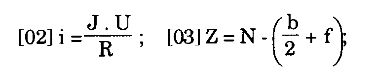


D= profondeur des aspérités
R= résistance du carreau à la gravure (P)
R₁= résistance du carreau au découpage (P)
les paramètres suivants sont minimizés:
J= force exercée par l'opérateur pour la gravure I
J₁= force exercée par l'opérateur pour le découpage T
f= distance du point d'appui (9'') des mâchoires (9,9') du bord de la machine
Y= tendance déviante de fracture
l= distance de la ligue de gravure du bord du carreau (P)
les paramètres suivants sont développés au maximum:
W= force exercée par le disque (08) de gravure
W₁= force exercée par les mâchoires (9,9')
b= distance entre les points extrêmes des outils pour presser 9, 9'
i=profondeur de gravure
U= efficacité de la puissance des leviers pour la gravure du carreau
U₁= efficacité de la puissance des leviers pour la fracture
Z= distance d'un point considéré du point initial de découpage
N= distance absolue du point considéré de l'extrémité de la machine et\ou de la ligne d'appui du carreau. - Méthode de découpage des carreaux, selon la revendication 7, caractérisée en ce que l'équipement de l'outil (8) est de dimensions telles à obtenir des conditions d'avantage et la position de la course est telle que la force demandée pour conduire l'outil le long de la course ne dépasse pas le pouvoir de l'usager pour maintenir essentiellement constante la force (J) dans tous les points de la course de gravure (I), à fin d'obtenir une profondeur (i) de gravure (I) constante.
- Méthode de découpage des carreaux, selon les revendications 7 et 8, caractérisée en ce que les forces (W₁) sont appliquées dans des points intérieurs (66) à fin de provoquer dans le carreau (P) un comportement, en ce qui concerne l'effet (Y) déviant, d'une barre appuyée à toutes les deux extrémités, réduisant essentiellement à un quart cet effet (Y) déviant, selon la formule connue: Mf=1. P\ 4.
- Méthode de découpage des carreaux, selon les revendications de la 7 à la 9, caractérisée en ce que toutes les machines (de la I à la V) de la série sont projetées et dimensionnées d'une façon que l'univers de dimensions des carreaux est compris parmi cinq machines (de I à V), où chacune de ces machinesa la capacité de couper des carreaux ayant des côtés ou des diagonales inférieurs à la course de l'outil (8).
- Méthode de découpage des carreaux, selon les revendications de la 7 à la 10, caractérisée en ce que la distributions des devoirs des machines de la série est réglementée par un graphique (figure 6), avec deux abscisses (Z et I) et deux ordonnées (R₁ et 1), représentatif des résistances (R₁) possibles, exprimées en pourcentage, dépassé lesquelles le carreau (P) se coupe en fonction aux distances réelles (Z), exprimées en cm, entre le point (66) d'application de la force et l'extrémité du carreau (P), ainsi que par rapport à la longueur (l), elle aussi exprimée en cm, de la bande (A) du carreau (P) qui doit être coupée et en plus de la possible profondeur (i) de gravure et des aspérités presumables, exprimées en pourcentage, où trois débits expérimentels de profondeur sont donnés: deux de gravure (i', i'') et un (D) des aspérités.
Applications Claiming Priority (3)
| Application Number | Priority Date | Filing Date | Title |
|---|---|---|---|
| IT08365390A IT1247658B (it) | 1990-12-31 | 1990-12-31 | Serie di macchine manuali, professionali,mediograndi,per il taglio di piastrelle durissime. |
| IT8365390 | 1990-12-31 | ||
| PCT/EP1991/002527 WO1992011985A1 (fr) | 1990-12-31 | 1991-12-31 | Serie de machines professionnelles de taille moyenne commandees a la main et destinees au decoupage de carreaux tres durs |
Publications (2)
| Publication Number | Publication Date |
|---|---|
| EP0565561A1 EP0565561A1 (fr) | 1993-10-20 |
| EP0565561B1 true EP0565561B1 (fr) | 1995-08-09 |
Family
ID=11323666
Family Applications (1)
| Application Number | Title | Priority Date | Filing Date |
|---|---|---|---|
| EP92901684A Expired - Lifetime EP0565561B1 (fr) | 1990-12-31 | 1991-12-31 | Machine de decoupage de carreaux |
Country Status (7)
| Country | Link |
|---|---|
| EP (1) | EP0565561B1 (fr) |
| AT (1) | ATE126121T1 (fr) |
| AU (1) | AU9132991A (fr) |
| DE (1) | DE69112083T2 (fr) |
| ES (1) | ES2078731T3 (fr) |
| IT (1) | IT1247658B (fr) |
| WO (1) | WO1992011985A1 (fr) |
Families Citing this family (11)
| Publication number | Priority date | Publication date | Assignee | Title |
|---|---|---|---|---|
| ES2064248B1 (es) * | 1992-12-15 | 1998-01-01 | Boada Germans Sa | Dispositivo posicionador en maquinas cortadoras-separadoras de piezas planas de ceramica y similares. |
| IT1265977B1 (it) * | 1993-01-18 | 1996-12-16 | Montolit Brevetti | Testata di macchina tagliapiastrelle accentrante le funzioni di incisione e di taglio, fisicamente e funzionalmente estensibile a |
| JP2973067B2 (ja) * | 1993-08-05 | 1999-11-08 | 産経物産株式会社 | タイルカッター |
| US5480081A (en) * | 1993-09-24 | 1996-01-02 | Diamant Boart, Inc. | Scoring and breaking device with a carrying case therefor |
| GB2378415A (en) * | 2001-08-11 | 2003-02-12 | Turner Intellect Property Ltd | A tile cutter |
| ITMI20022075A1 (it) * | 2002-10-01 | 2004-04-02 | Montolit Brevetti | Tagliapiastrelle manuale perfezionata |
| GB0917687D0 (en) * | 2009-10-08 | 2009-11-25 | 7Rdd Ltd | Cutting tool and method of use thereof |
| CN105269706B (zh) * | 2015-11-17 | 2017-03-22 | 广西双迎门业有限公司 | 一种罗马头大花边的45度切割架 |
| CN111531727B (zh) * | 2020-05-13 | 2022-03-22 | 永康市煌丰工贸有限公司 | 切割机 |
| IT202300001176A1 (it) * | 2023-01-26 | 2024-07-26 | Brevetti Montolit S P A | Sistema di sospensione per tagliapiastrelle |
| EP4655147A1 (fr) * | 2023-01-26 | 2025-12-03 | Brevetti Montolit S.P.A. | Système de suspension pour machines de découpe de carreaux |
Family Cites Families (9)
| Publication number | Priority date | Publication date | Assignee | Title |
|---|---|---|---|---|
| DE318466C (fr) * | ||||
| FR1356714A (fr) * | 1963-05-13 | 1964-03-27 | Mec Montoli Vincenzo Off | Tranche à couper les carreaux de revêtement, en particulier ceux en céramique |
| FR1563916A (fr) * | 1968-02-23 | 1969-04-18 | ||
| FR2294029A1 (fr) * | 1974-12-13 | 1976-07-09 | Muller Alfred | Dispositif de coupe en particulier pour le sectionnement de carreaux |
| US4444174A (en) * | 1982-01-18 | 1984-04-24 | Plas Plugs Limited | Tile parting devices |
| IT8360940V0 (it) * | 1983-10-07 | 1983-10-07 | Cantecno Srl | Macchina leggerissima e maneggevole per il taglio di piastrelle piccole e medie particolarmente per dilettanti. |
| US4679476A (en) * | 1986-04-03 | 1987-07-14 | Edward Abreu | Scoring guide and glass cutter system |
| DE8715018U1 (de) * | 1987-11-11 | 1987-12-23 | Erich vom Berg Leichtmetallgießerei und Herstellung von Werkzeugen, 5884 Halver | Fliesenschneidevorrichtung |
| IT1220363B (it) * | 1988-05-13 | 1990-06-15 | Gianni Tagliaferro | Apparecchiatura equipaggiata per il taglio mediante troncatura di parti compelementari di mattonelle,marmette,piastrelle e simili da pavimentazione e da rivestimento di pareti |
-
1990
- 1990-12-31 IT IT08365390A patent/IT1247658B/it active IP Right Grant
-
1991
- 1991-12-31 DE DE69112083T patent/DE69112083T2/de not_active Expired - Lifetime
- 1991-12-31 EP EP92901684A patent/EP0565561B1/fr not_active Expired - Lifetime
- 1991-12-31 WO PCT/EP1991/002527 patent/WO1992011985A1/fr not_active Ceased
- 1991-12-31 ES ES92901684T patent/ES2078731T3/es not_active Expired - Lifetime
- 1991-12-31 AU AU91329/91A patent/AU9132991A/en not_active Abandoned
- 1991-12-31 AT AT92901684T patent/ATE126121T1/de not_active IP Right Cessation
Also Published As
| Publication number | Publication date |
|---|---|
| DE69112083T2 (de) | 1996-05-02 |
| AU9132991A (en) | 1992-08-17 |
| WO1992011985A1 (fr) | 1992-07-23 |
| IT9083653A1 (it) | 1992-07-01 |
| DE69112083D1 (de) | 1995-09-14 |
| ES2078731T3 (es) | 1995-12-16 |
| IT1247658B (it) | 1994-12-28 |
| IT9083653A0 (it) | 1990-12-31 |
| EP0565561A1 (fr) | 1993-10-20 |
| ATE126121T1 (de) | 1995-08-15 |
Similar Documents
| Publication | Publication Date | Title |
|---|---|---|
| EP0565561B1 (fr) | Machine de decoupage de carreaux | |
| GB1602152A (en) | Apparatus with motor driven peeling device | |
| EP0608476B1 (fr) | Dispositif à couper des carreaux | |
| US3439664A (en) | Masonry cutter | |
| US5605086A (en) | Compound mitre saw | |
| EP0501053A1 (fr) | Dispositif de coupe de carreaux | |
| MY110082A (en) | Elongated cutting tool, for wood working and apparatus for and method of grinding the same | |
| US12485582B2 (en) | Low-dust cutting device for multiple tiles and low-dust scoring device for concrete masonry units | |
| US5558565A (en) | Glass pattern cutting device | |
| JP3121921U (ja) | 鋏自動研磨装置 | |
| US20060288835A1 (en) | Table saw fence push guide | |
| CN221949324U (zh) | 一种用于鞋类原料裁切的裁断机 | |
| CN220295742U (zh) | 一种钢筋切断装置 | |
| CN220278157U (zh) | 一种辅助夹持的液压切排机 | |
| JPS636371Y2 (fr) | ||
| CN211942680U (zh) | 一种分页裁切装订一体机 | |
| CN223423017U (zh) | 碳纤维布手动剪切器 | |
| CN213469753U (zh) | 一种钢料裁切机的置平装置 | |
| CN221186885U (zh) | 木质家具制造用板材切割装置 | |
| CN212886997U (zh) | 一种角磨机机架 | |
| CN219043943U (zh) | 一种裁切机 | |
| CN223477883U (zh) | 一种用于板材加工的刨床 | |
| CN2148648Y (zh) | 多功能木工刨锯机械 | |
| CN219633926U (zh) | 一种xpe席纹汽车脚垫边缘修整装置 | |
| JP3234776U (ja) | 切断装置 |
Legal Events
| Date | Code | Title | Description |
|---|---|---|---|
| PUAI | Public reference made under article 153(3) epc to a published international application that has entered the european phase |
Free format text: ORIGINAL CODE: 0009012 |
|
| 17P | Request for examination filed |
Effective date: 19930802 |
|
| AK | Designated contracting states |
Kind code of ref document: A1 Designated state(s): AT BE CH DE DK ES FR GB GR IT LI LU MC NL SE |
|
| 17Q | First examination report despatched |
Effective date: 19931109 |
|
| GRAA | (expected) grant |
Free format text: ORIGINAL CODE: 0009210 |
|
| AK | Designated contracting states |
Kind code of ref document: B1 Designated state(s): AT BE CH DE DK ES FR GB GR IT LI LU MC NL SE |
|
| PG25 | Lapsed in a contracting state [announced via postgrant information from national office to epo] |
Ref country code: NL Free format text: LAPSE BECAUSE OF NON-PAYMENT OF DUE FEES Effective date: 19950809 Ref country code: MC Free format text: LAPSE BECAUSE OF NON-PAYMENT OF DUE FEES Effective date: 19950809 Ref country code: GR Free format text: LAPSE BECAUSE OF FAILURE TO SUBMIT A TRANSLATION OF THE DESCRIPTION OR TO PAY THE FEE WITHIN THE PRESCRIBED TIME-LIMIT Effective date: 19950809 Ref country code: DK Effective date: 19950809 Ref country code: BE Effective date: 19950809 |
|
| REF | Corresponds to: |
Ref document number: 126121 Country of ref document: AT Date of ref document: 19950815 Kind code of ref document: T |
|
| REF | Corresponds to: |
Ref document number: 69112083 Country of ref document: DE Date of ref document: 19950914 |
|
| ITF | It: translation for a ep patent filed | ||
| PG25 | Lapsed in a contracting state [announced via postgrant information from national office to epo] |
Ref country code: SE Effective date: 19951109 |
|
| ET | Fr: translation filed | ||
| REG | Reference to a national code |
Ref country code: ES Ref legal event code: FG2A Ref document number: 2078731 Country of ref document: ES Kind code of ref document: T3 |
|
| PG25 | Lapsed in a contracting state [announced via postgrant information from national office to epo] |
Ref country code: LU Free format text: LAPSE BECAUSE OF NON-PAYMENT OF DUE FEES Effective date: 19951231 |
|
| NLV1 | Nl: lapsed or annulled due to failure to fulfill the requirements of art. 29p and 29m of the patents act | ||
| PLBE | No opposition filed within time limit |
Free format text: ORIGINAL CODE: 0009261 |
|
| STAA | Information on the status of an ep patent application or granted ep patent |
Free format text: STATUS: NO OPPOSITION FILED WITHIN TIME LIMIT |
|
| 26N | No opposition filed | ||
| REG | Reference to a national code |
Ref country code: GB Ref legal event code: IF02 |
|
| PGFP | Annual fee paid to national office [announced via postgrant information from national office to epo] |
Ref country code: ES Payment date: 20091218 Year of fee payment: 19 Ref country code: CH Payment date: 20091202 Year of fee payment: 19 Ref country code: AT Payment date: 20091215 Year of fee payment: 19 |
|
| PGFP | Annual fee paid to national office [announced via postgrant information from national office to epo] |
Ref country code: GB Payment date: 20091218 Year of fee payment: 19 Ref country code: FR Payment date: 20100106 Year of fee payment: 19 |
|
| PGFP | Annual fee paid to national office [announced via postgrant information from national office to epo] |
Ref country code: DE Payment date: 20100224 Year of fee payment: 19 |
|
| PGFP | Annual fee paid to national office [announced via postgrant information from national office to epo] |
Ref country code: IT Payment date: 20101222 Year of fee payment: 20 |
|
| REG | Reference to a national code |
Ref country code: CH Ref legal event code: PL |
|
| GBPC | Gb: european patent ceased through non-payment of renewal fee |
Effective date: 20101231 |
|
| PG25 | Lapsed in a contracting state [announced via postgrant information from national office to epo] |
Ref country code: AT Free format text: LAPSE BECAUSE OF NON-PAYMENT OF DUE FEES Effective date: 20101231 |
|
| REG | Reference to a national code |
Ref country code: FR Ref legal event code: ST Effective date: 20110831 |
|
| PG25 | Lapsed in a contracting state [announced via postgrant information from national office to epo] |
Ref country code: CH Free format text: LAPSE BECAUSE OF NON-PAYMENT OF DUE FEES Effective date: 20101231 Ref country code: LI Free format text: LAPSE BECAUSE OF NON-PAYMENT OF DUE FEES Effective date: 20101231 Ref country code: FR Free format text: LAPSE BECAUSE OF NON-PAYMENT OF DUE FEES Effective date: 20110103 |
|
| PG25 | Lapsed in a contracting state [announced via postgrant information from national office to epo] |
Ref country code: GB Free format text: LAPSE BECAUSE OF NON-PAYMENT OF DUE FEES Effective date: 20101231 Ref country code: DE Free format text: LAPSE BECAUSE OF NON-PAYMENT OF DUE FEES Effective date: 20110701 |
|
| REG | Reference to a national code |
Ref country code: DE Ref legal event code: R119 Ref document number: 69112083 Country of ref document: DE Effective date: 20110701 |
|
| REG | Reference to a national code |
Ref country code: ES Ref legal event code: FD2A Effective date: 20120206 |
|
| PG25 | Lapsed in a contracting state [announced via postgrant information from national office to epo] |
Ref country code: ES Free format text: LAPSE BECAUSE OF NON-PAYMENT OF DUE FEES Effective date: 20110101 |