EP0565572B1 - Verfahren und vorrichtung zum kontrollieren der konzentration zumindest einer komponente einer gasmischung in einem narkosesystem - Google Patents
Verfahren und vorrichtung zum kontrollieren der konzentration zumindest einer komponente einer gasmischung in einem narkosesystem Download PDFInfo
- Publication number
- EP0565572B1 EP0565572B1 EP92902169A EP92902169A EP0565572B1 EP 0565572 B1 EP0565572 B1 EP 0565572B1 EP 92902169 A EP92902169 A EP 92902169A EP 92902169 A EP92902169 A EP 92902169A EP 0565572 B1 EP0565572 B1 EP 0565572B1
- Authority
- EP
- European Patent Office
- Prior art keywords
- concentration
- gas mixture
- component
- anaesthetic
- gas
- Prior art date
- Legal status (The legal status is an assumption and is not a legal conclusion. Google has not performed a legal analysis and makes no representation as to the accuracy of the status listed.)
- Expired - Lifetime
Links
Images

Classifications
-
- A—HUMAN NECESSITIES
- A61—MEDICAL OR VETERINARY SCIENCE; HYGIENE
- A61M—DEVICES FOR INTRODUCING MEDIA INTO, OR ONTO, THE BODY; DEVICES FOR TRANSDUCING BODY MEDIA OR FOR TAKING MEDIA FROM THE BODY; DEVICES FOR PRODUCING OR ENDING SLEEP OR STUPOR
- A61M16/00—Devices for influencing the respiratory system of patients by gas treatment, e.g. ventilators; Tracheal tubes
- A61M16/10—Preparation of respiratory gases or vapours
- A61M16/104—Preparation of respiratory gases or vapours specially adapted for anaesthetics
-
- A—HUMAN NECESSITIES
- A61—MEDICAL OR VETERINARY SCIENCE; HYGIENE
- A61M—DEVICES FOR INTRODUCING MEDIA INTO, OR ONTO, THE BODY; DEVICES FOR TRANSDUCING BODY MEDIA OR FOR TAKING MEDIA FROM THE BODY; DEVICES FOR PRODUCING OR ENDING SLEEP OR STUPOR
- A61M16/00—Devices for influencing the respiratory system of patients by gas treatment, e.g. ventilators; Tracheal tubes
- A61M16/0003—Accessories therefor, e.g. sensors, vibrators, negative pressure
- A61M2016/003—Accessories therefor, e.g. sensors, vibrators, negative pressure with a flowmeter
-
- A—HUMAN NECESSITIES
- A61—MEDICAL OR VETERINARY SCIENCE; HYGIENE
- A61M—DEVICES FOR INTRODUCING MEDIA INTO, OR ONTO, THE BODY; DEVICES FOR TRANSDUCING BODY MEDIA OR FOR TAKING MEDIA FROM THE BODY; DEVICES FOR PRODUCING OR ENDING SLEEP OR STUPOR
- A61M16/00—Devices for influencing the respiratory system of patients by gas treatment, e.g. ventilators; Tracheal tubes
- A61M16/10—Preparation of respiratory gases or vapours
- A61M16/1005—Preparation of respiratory gases or vapours with O2 features or with parameter measurement
- A61M2016/102—Measuring a parameter of the content of the delivered gas
- A61M2016/1035—Measuring a parameter of the content of the delivered gas the anaesthetic agent concentration
Definitions
- the present invention relates to an apparatus for controlling the concentration of at least one component in a gas mixture in an anaesthetic system comprising an inhalation branch, a dosing unit for supplying the component, and a control unit for controlling the supply.
- Such a device can be employed in inhalation anaesthetics, e.g. for controlling the concentration of the anaesthetic given to the patient in a gas mixture.
- the invention also concerns a method for controlling the concentration of at least one component in a gas mixture in an anaesthetic system.
- One way of reducing the consumption of anaesthetics is to use an anaesthetic system with total or partial re-inhalation.
- total re-inhalation no gas escapes from the system, and the patient is breathing essentially the same gas mixture all the time.
- the carbon dioxide exhaled by the patient is eliminated in a CO 2 absorber, and oxygen and the anaesthetic are supplied to maintain the concentrations thereof at the desired level.
- partial re-inhalation only part of the exhaled gas mixture is inhaled again, and a certain amount of fresh gas mixture is instead supplied. The gas surplus is discharged during exhalation. If the consumption of anaesthetics is to be minimised, a system with total re-inhalation is the best option.
- Controlling the concentration of anaesthetics in anaesthetic systems with re-inhalation is today often performed manually.
- the anaesthetist sometimes may consult a gas-concentration meter mounted in the anaesthetic system and serving to measure the concentration of the anaesthetic.
- WO 88/06904 discloses an apparatus for controlling the concentration of a component in a gas mixture given to the patient.
- the apparatus includes a patient circuit which consists of a circle system for re-inhalation, which has an inhalation branch and an exhalation branch.
- a gas-concentration meter for measuring the concentration of the component in the gas mixture is provided in the inhalation branch close to the patient and is connected to a computer.
- a desired-value transducer for setting the desired concentration of the gas component is also connected to the computer.
- the computer controls a gas-dosing unit which is provided further away from the patient in the inhalation branch, to give the desired concentration of the gas component.
- this is a feedback control.
- the object of the present invention is, therefore, to provide an apparatus which enables automatic and highly accurate adjustment to the desired value of the concentration of a component in the gas mixture in an anaesthetic system, there being but a brief time delay.
- This apparatus enables accurate and rapid control of the concentration of a component in the gas mixture, since the computer, knowing the flow rate of the gas mixture in the inhalation branch and the concentration of the component in the gas mixture before the dosing point, can determine the flow rate of the supplied component needed to give the desired concentration. Thus, this is a feed forward control.
- the flow rate in the inhalation branch is unknown, it is conveniently measured by a flow meter provided e.g. in the inhalation branch.
- the dosing unit is advantageously disposed downstream from the flow meter in the inhalation branch, so that the flow meter measures the flow rate of the gas mixture before the dosing point.
- the dosing point and the concentration meter are preferably arranged close to one another.
- the volume contained by the anaesthetic system between the these two components should not exceed 2 l, and should preferably not be higher than 200 ml.
- the flow meter, the gas-concentration meter and the dosing unit are advantageously arranged in one and the same unit, which simplifies mounting in the anaesthetic system.
- This unit should be mounted at a distance from the patient, to prevent the measuring devices from being affected by phlegm, moisture and the like emanating from the patient.
- the apparatus may include an additional gas-concentration meter for measuring the concentration of the component downstream from the dosing point.
- This gas-concentration meter may perform a monitoring function, guarding against too high a discrepancy between the desired and the obtained concentration of the component in the gas mixture in the inhalation branch, or form part of a feedback circuit for refining the control.
- the above apparatus can be employed in open anaesthetic systems, as well as in anaesthetic systems with total or partial re-inhalation. The greatest advantages are, however, obtained with re-inhalation systems.
- the apparatus is applicable to anaesthetic systems with spontaneous or controlled breathing.
- the invention also concerns a method for performing the control, which has the distinctive features recited in the appended claims.
- Fig. 1 schematically illustrates an anaesthetic system 1 for re-inhalation, which comprises an inhalation branch 2, an exhalation branch 3, a patient's element 4 and a pair of bellows 5.
- an inhalation branch 2 is mounted in the inhalation branch 2 and a device 7 for controlling the concentration of a component, e.g. an anaesthetic, in the gas mixture circulating in the anaesthetic system.
- a device for supplying fresh gas (not shown).
- the gas mixture in the anaesthetic system flows in the directions indicated by the arrows.
- the inhalation branch 2 and the exhalation branch 3 there is a one-way flow, whereas there is a two-way flow in the patient's element 4 and the piece connecting the inhalation and exhalation branches to the pair of bellows 5.
- Fig. 2 is a basic diagram illustrating an apparatus according to the invention.
- the apparatus includes a first gas-concentration meter 8 adapted to measure the concentration of the anaesthetic in the gas mixture in the inhalation branch 2 (of which only a part is shown in the Figure); a flow meter 9 adapted to measure the flow rate of the gas mixture in the inhalation branch 2; a dosing unit 10 adapted to supply the anaesthetic at a dosing point 30 in the inhalation branch 2; an additional concentration meter 11 also adapted to measure the concentration of the anaesthetic in the gas mixture; a desired-value transducer 13 serving to set the desired concentration of the anaesthetic in the gas mixture for inhalation; and a control unit 12 adapted to receive input signals from the concentration meter 8, the flow meter 9, the concentration meter 11 and the desired-value transducer 13, as well as to calculate and transmit a control signal to the dosing unit 10.
- the concentration meter 8 and the flow meter 9 are provided upstream from the dosing point 30, and are, in other words, located further away from the patient than is the dosing point 30.
- the concentration meter 8 and the flow meter 9 thus measure the concentration of the anaesthetic and the flow rate of re-inhaled gas.
- the relative positions of the concentration meter 8 and the flow meter 9 are without interest.
- the apparatus illustrated in Fig. 2 operates as follows.
- the anaesthetist sets the desired concentration of the anaesthetic in the inhalation gas by means of the desired-value transducer 13 which transmits to the control unit 12 an input signal to this effect.
- This simple control algorithm adjusts itself automatically to any changes in the ventilation pattern or the degree of re-inhalation. In addition, it responds rapidly when the desired concentration of anaesthetic is altered.
- the concentration meter 8 and the dosing point 30 are advantageously located close to one another.
- the volume therebetween in the inhalation branch should not exceed 2 l, preferably not 200 ml, so that the anaesthetic is supplied in the flow in which a corresponding measuring of the concentration has been effected.
- the additional concentration meter 11 is not essential to the function of the apparatus. This meter is disposed downstream from the dosing point 30, and is used for measuring the obtained concentration of the anaesthetic. It may serve as a safety device, guarding against too high a discrepancy between the desired and the obtained concentration of the anaesthetic. It might also be employed in a feedback method for refining the feed forward control.
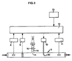
- Fig. 3 corresponds to Fig. 2, excepting an inlet 14 for supplying O 2 and N 2 O/air from conventional rotameters.
- a flow meter 15 adapted to measure the flow rate of O 2 and N 2 O/air is mounted in the inlet 14.
- the anaesthetist manually adjusts the flow rate of O 2 and N 2 O/air by means of the rotameters.
- a concentration meter (not shown) is conveniently arranged in the inlet 14 or in the inhalation branch 2 for measuring the oxygen concentration and transmitting a signal to the control unit 12.
- the inlet 14 is preferably provided downstream from the concentration meter 8 and the flow meter 9, for the following reason.
- the flow of re-inhaled gas in the inhalation branch 2 is essentially non-existent. There is, however, obtained a flow from the rotameter in to the inhalation branch 2, via the inlet 14. If this flow from the rotameter is supplied before the concentration meter 8, the concentration of anaesthetic measured by this meter will vary to a greater extent than if the flow is supplied ahead of the concentration meter. Since concentration meters are fairly slow, they should preferably measure a slowly varying signal.
- the supply of oxygen and N 2 O/air may also be automatic. If so, the anaesthetist sets the desired concentration of oxygen or N 2 O or nitrogen gas by means of the desired-value transducer 13. Control of the concentration of oxygen or N 2 O or nitrogen gas in the inhalation branch is then performed in the manner described above in connection with the control of the concentration of anaesthetic. It goes without saying that the concentration meter 8 then has to be able to measure the concentrations of these substances.
- the device shown in Fig. 2 was tested in an anaesthetic system connected to a test lung.
- the concentration meters 8, 11 employed were commercially available anaesthetic-gas meters, and the flow meter 9 was a pneumotachograph connected to a differential-pressure transducer.
- the control unit 12 employed was a computer connected to the concentration-meters 8, 11, the flow meter 9 and the dosing unit 10 via analog inputs and outputs.
- the anaesthetist selected the desired concentration of isoflurane (an anaesthetic).
- the flow rate at which isoflurane was to be supplied was determined according to formula (1) above.
- the isoflurane was dosed in the form of a highly concentrated gas mixture with a content of about 40% of air/oxygen.
- the supply rate was modulated by supplying the highly concentrated isoflurane mixture in brief (0.1 s), equal pulses with a frequence proportionate to the isoflurane flow rate determined by the control algorithm in the control unit 12.
- the resulting inhaled isoflurane concentration was measured by means of the gas-concentration meter 11.
- a mixing volume was placed between the dosing point 30 and the additional concentration meter 11 to compensate for the fact that the pulses of isoflurane gas were not infinitely small.
- the apparatus according to the invention was connected in an almost closed system whose fundamental features are described in Anaesthesia 45, pp 855-858, 1990.
- the desired isoflurane concentration was varied between 0.5% and 2.0%.
- the resulting concentrations were as desired.
- the invention makes it possible to control the amount of anaesthetic in a simple manner, so as to obtain the desired concentration in the inhalation gas.
- the control is independent of the degree of re-inhalation, which is continuously measured and compensated for by the control unit. Since the control system is of simple construction, the technical safety is satisfactory.
- the fact that the entire equipment can be arranged as a unit in the inhalation branch of the anaesthetic system and be stationarily mounted on the anaesthetic trolley also contributes to the safety.
- the anaesthetist communicates with the control system in the simplest possible way: the desired inhaled concentration of anaesthetic, optionally also of oxygen, is indicated.
- the invention is applicable to the control of all the gas components in the anaesthetic system, i.e. anaesthetics as well as oxygen and air/nitrogen gas.
- the invention may be utilised also for lowering the concentration of anaesthetic in the inhalation gas, which is performed by increasing the concentrations of the other gas components.
Landscapes
- Health & Medical Sciences (AREA)
- Life Sciences & Earth Sciences (AREA)
- General Health & Medical Sciences (AREA)
- Engineering & Computer Science (AREA)
- Anesthesiology (AREA)
- Biomedical Technology (AREA)
- Heart & Thoracic Surgery (AREA)
- Pulmonology (AREA)
- Hematology (AREA)
- Animal Behavior & Ethology (AREA)
- Emergency Medicine (AREA)
- Public Health (AREA)
- Veterinary Medicine (AREA)
- Pharmaceuticals Containing Other Organic And Inorganic Compounds (AREA)
- Respiratory Apparatuses And Protective Means (AREA)
- Infusion, Injection, And Reservoir Apparatuses (AREA)
- Medicinal Preparation (AREA)
Claims (10)
- Vorrichtung zum Steuern der Konzentration wenigstens eines Bestandteils in einem Gasgemisch in einem Narkose-Reinhalationssystem (1), das eine Inhalationsleitung (2), eine Exhalationsleitung (3), die mit der Inhalationsleitung (1) verbunden ist, einen Gaskonzentrationsmesser (8), der in der Inhalationsleitung (2) vorhanden ist, eine Dosiereinheit (10), die der Inhalationsleitung (2) den Bestandteil zuführt, sowie eine Steuereinheit (12, 13) umfaßt, die die Zufuhr des Bestandteils als Funktion der durch den Gaskonzentrationsmesser (18) gemessenen Konzentration steuert, dadurch gekennzeichnet, daß die Vorrichtung so eingerichtet ist, daß die Dosiereinheit (10) den Bestandteil der Inhalationsleitung (2) an einem Punkt (30) zuführt, der sich stromab von dem Gaskonzentrationsmesser (8) längs der Leitung befindet, und daß die Steuereinheit (12, 13) des weiteren so eingerichtet ist, daß sie die Zufuhr des Bestandteils als Funktion der Strömungsgeschwindigkeit des Gasgemisches in der Inhalationsleitung (2) steuert.
- Vorrichtung nach Anspruch 1, gekennzeichnet durch einen Strömungsmesser (9), der die Strömungsgeschwindigkeit des Gasgemisches in der Inhalationsleitung (2) mißt.
- Vorrichtung nach Anspruch 2, dadurch gekennzeichnet, daß der Strömungsmesser(9) in der Inhalationsleitung (2) vorhanden ist.
- Vorrichtung nach Anspruch 2 oder 3, dadurch gekennzeichnet, daß sich der Dosierpunkt (30) stromab von dem Strömungsmesser (9) befindet.
- Vorrichtung nach einem der vorangehenden Ansprüche, dadurch gekennzeichnet, daß das Volumen, das von der Inhalationsleitung (2) zwischen dem Gaskonzentrationsmesser (8) und dem Dosierpunkt (30) aufgenommen wird, unter 2 l, vorzugsweise unter 200 ml liegt.
- Vorrichtung nach einem der vorangehenden Ansprüche, dadurch gekennzeichnet, daß der Gaskonzentrationsmesser (8), der Strömungsmesser (9) und die Dosiereinheit (10) in einer Einheit (7) angeordnet sind, die in der Inhalationsleitung (2) angebracht werden kann.
- Vorrichtung nach einem der vorangehenden Ansprüche, gekennzeichnet durch einen zusätzlichen Konzentrationsmesser (11), der die Konzentration des Bestandteils im Atemgas in der Inhalationsleitung (2) mißt und stromab von dem Dosierpunkt (30) in der Inhalationsleitung (2) angeordnet ist.
- Vorrichtung nach einem der vorangehenden Ansprüche, wobei es sich bei dem Bestandteil um ein Anästhetikum handelt, gekennzeichnet durch einen Einlaß (14) für die Zufuhr eines frischen Gasgemischs, der in der Inhalationsleitung (2) stromab von dem Gaskonzentrationsmesser (8) angeordnet ist, wobei die Steuereinheit (12, 13) bei der Steuerung der Zufuhr des Anästhetikums die Strömungsgeschwindigkeit des frischen Gasgemischs berücksichtigt, das über die Inhalationsleitung (2) zugeführt wird.
- Verfahren zum Steuern der Konzentrations wenigstens eines Bestandteils in einem Gasgemisch in einem Narkose-Reinhaltationssystem, das eine Inhalationsleitung und eine Exhalationsleitung umfaßt, die mit der Inhalationsleitung verbunden ist, wobei die Konzentration des Bestandteils in dem Gasgemisch in der Inhalationsleitung stromauf von dem Punkt gemessen wird, an dem der Bestandteil dem Gasgemisch in der Inhalationsleitung zugeführt wird, und der Bestandteil mit einer Strömungsgeschwindigkeit zugeführt wird, die von der gemessenen Konzentration des Bestandteils und der Strömungsgeschwindigkeit des Gasgemischs in der Inhalationsleitung abhängt.
- Verfahren nach Anspruch 9, dadurch gekennzeichnet, daß die Strömungsgeschwindigkeit, mit der der Bestandteil zuzuführen ist, entsprechend der folgenden Formel bestimmt wird:
 Vv: die Strömungsgeschwindigkeit, mit der der Bestandteil zuzuführen ist,Vi: die Strömungsgeschwindigkeit des Gasgemischs,Ci: die gewünschte Konzentration des Bestandteils in dem Gasgemisch in Prozent, undCr: die gemessene Konzentration des Bestandteils in Prozent.
Applications Claiming Priority (3)
| Application Number | Priority Date | Filing Date | Title |
|---|---|---|---|
| SE9100016 | 1991-01-03 | ||
| SE9100016A SE9100016D0 (sv) | 1991-01-03 | 1991-01-03 | Foerfarande och anordning att reglera inandad koncentration av gas i en anestesikrets |
| PCT/SE1991/000904 WO1992011887A1 (en) | 1991-01-03 | 1991-12-23 | Method and apparatus for controlling the concentration of at least one component in a gas mixture in an anaesthetic system |
Publications (2)
| Publication Number | Publication Date |
|---|---|
| EP0565572A1 EP0565572A1 (de) | 1993-10-20 |
| EP0565572B1 true EP0565572B1 (de) | 1997-03-05 |
Family
ID=20381531
Family Applications (1)
| Application Number | Title | Priority Date | Filing Date |
|---|---|---|---|
| EP92902169A Expired - Lifetime EP0565572B1 (de) | 1991-01-03 | 1991-12-23 | Verfahren und vorrichtung zum kontrollieren der konzentration zumindest einer komponente einer gasmischung in einem narkosesystem |
Country Status (6)
| Country | Link |
|---|---|
| US (1) | US5619986A (de) |
| EP (1) | EP0565572B1 (de) |
| JP (1) | JPH06503977A (de) |
| DE (1) | DE69125027T2 (de) |
| SE (1) | SE9100016D0 (de) |
| WO (1) | WO1992011887A1 (de) |
Families Citing this family (20)
| Publication number | Priority date | Publication date | Assignee | Title |
|---|---|---|---|---|
| SE501074C2 (sv) * | 1993-07-22 | 1994-11-07 | Siemens Elema Ab | Gasblandning och apparat för att tillföra gasblandningen till lungorna hos ett levande väsen |
| SE9302477L (sv) * | 1993-07-22 | 1995-01-23 | Siemens Elema Ab | Apparat för tillförsel av andningsgas |
| US5615669A (en) * | 1994-07-22 | 1997-04-01 | Siemens Elema Ab | Gas mixture and device for delivering the gas mixture to the lungs of a respiratory subject |
| JP3175138B2 (ja) * | 1994-11-22 | 2001-06-11 | 横河電機株式会社 | バスインターフェイス装置 |
| SE506778C2 (sv) * | 1996-08-12 | 1998-02-09 | Siemens Elema Ab | Förfarande vid blandning av gaser och en anordning för blandning av gaser |
| AUPO163896A0 (en) * | 1996-08-14 | 1996-09-05 | Resmed Limited | Determination of respiratory airflow |
| DE19639522A1 (de) * | 1996-09-26 | 1998-04-16 | Draegerwerk Ag | Beatmungsgerät |
| US5806513A (en) * | 1996-10-11 | 1998-09-15 | Ohmeda Inc. | Method and apparatus for controlling a medical anesthesia delivery system |
| US5803064A (en) * | 1997-08-12 | 1998-09-08 | University Technology Corporation | Anesthesia system for use with magnetic resonance imaging systems |
| US6216690B1 (en) | 1997-10-15 | 2001-04-17 | Datex-Ohmeda, Inc. | Method and apparatus for rapid control of set inspired gas concentration in anesthesia delivery systems |
| DE19745954A1 (de) * | 1997-10-17 | 1999-04-22 | Bernd Horst Dr Meier | Verfahren und Vorrichtung zur Messung von Gasgemischen |
| ES2139540B1 (es) * | 1998-04-14 | 2000-09-01 | Mas Marfany Jaime | Metodo de control automatico para el aporte de anestesico a un circuito cerrado a bajos flujos. |
| US6634355B2 (en) * | 1999-06-11 | 2003-10-21 | Colas Marie-Jose | Single breath induction anesthesia apparatus |
| EP1226432B1 (de) * | 1999-10-11 | 2006-06-07 | Koninklijke Philips Electronics N.V. | Differenzielle gasmessung, insbesondere um atemgas zu analysieren |
| US20060006354A1 (en) * | 2002-12-04 | 2006-01-12 | Fatih Guler | Optical sensors and algorithms for controlling automatic bathroom flushers and faucets |
| DE102006027052B3 (de) * | 2006-06-10 | 2007-08-09 | Dräger Medical AG & Co. KG | Verfahren zur Messung des Anästhesiemittelverbrauchs in einem Beatmungssystem |
| US8752548B2 (en) * | 2007-06-28 | 2014-06-17 | Maquet Critical Care Ab | Patient ventilation system with a gas identification unit |
| US8267081B2 (en) * | 2009-02-20 | 2012-09-18 | Baxter International Inc. | Inhaled anesthetic agent therapy and delivery system |
| CA2868887A1 (en) | 2012-03-29 | 2013-10-03 | Joseph Fisher | Anesthetic delivery system |
| GB2526539B (en) * | 2014-05-23 | 2016-11-02 | Penlon Ltd | Vaporizer |
Family Cites Families (20)
| Publication number | Priority date | Publication date | Assignee | Title |
|---|---|---|---|---|
| DE1931354C3 (de) * | 1969-06-20 | 1974-10-24 | Draegerwerk Ag, 2400 Luebeck | Verfahren zum Mischen von Gasen und Gasmischgerät für Gase, insbesondere für Atmungs- und medizinische Geräte |
| DE2455751B2 (de) * | 1974-11-26 | 1978-05-11 | Draegerwerk Ag, 2400 Luebeck | Verfahren zum Mischen von Druckgasen und ein Gasmischgerät dazu |
| US4150670A (en) * | 1977-11-14 | 1979-04-24 | University Patents, Inc. | Anesthesia detector and display apparatus |
| JPS55166163A (en) * | 1979-06-13 | 1980-12-25 | Citizen Watch Co Ltd | Controller for anesthetic gas |
| SE434438B (sv) * | 1980-02-21 | 1984-07-23 | Gambro Engstrom Ab | Anordning for detektering av forekomsten av en given gaskomponent i en gasblandning |
| SE434799B (sv) * | 1980-06-18 | 1984-08-20 | Gambro Engstrom Ab | Sett och anordning for styrning av en lungventilator |
| SE430213B (sv) * | 1981-03-10 | 1983-10-31 | Siemens Elema Ab | Respirator, avsedd att anslutas till andningsvegarna pa menniska eller djur |
| SE428345C (sv) * | 1981-12-23 | 1989-04-17 | Gambro Engstrom Ab | Foerfarande vid maetning och anordning foer maetning av koncentrationen av en eller flera givna komponenter i en av en patient in- och eller utandad andningsgas |
| NL191481C (nl) * | 1983-04-05 | 1995-08-04 | Draegerwerk Ag | Inrichting voor anesthesie met terugademing. |
| SE449566B (sv) * | 1984-06-28 | 1987-05-11 | Gambro Engstrom Ab | Narkos- och/eller respiratoranleggning med alternativt manuellt driven pump |
| US4587967A (en) * | 1985-07-09 | 1986-05-13 | Lifecare Services, Inc. | Oxygen enriched reciprocating piston respirator |
| US4770168A (en) * | 1985-12-16 | 1988-09-13 | Tibor Rusz | Electrically controllable anesthesia vaporizer |
| SE8700977D0 (sv) * | 1987-03-09 | 1987-03-09 | Olof Werner | Enhet som i olika grad separerar gasinnehallet i drivkrets och mottagarkrets, men som enda tillater gasgenomslepp i bada riktningarna (oppen separation) |
| DE3712598A1 (de) * | 1987-04-14 | 1988-10-27 | Siemens Ag | Inhalations-anaesthesiegeraet |
| SE459155B (sv) * | 1987-04-14 | 1989-06-12 | Siemens Elema Ab | Foerfarande och anording foer aateranvaendning av anestesimedel |
| JPS6449541A (en) * | 1987-08-19 | 1989-02-27 | Anzai Sogyo Co Ltd | Xenon gas inhalation system |
| US5094235A (en) * | 1989-05-10 | 1992-03-10 | Dragerwerk Aktiengesellschaft | Anesthesia ventilating apparatus having a breathing circuit and control loops for anesthetic gas components |
| DE3924123C2 (de) * | 1989-07-20 | 1994-01-27 | Draegerwerk Ag | Vorrichtung zur Erzeugung und Dosierung eines Gasgemisches |
| SE467996B (sv) * | 1991-01-25 | 1992-10-19 | Siemens Elema Ab | Anordning foer tillfoersel av en andningsgas och minst ett anestesimedel |
| DE4107060C2 (de) * | 1991-03-06 | 1999-07-01 | Draegerwerk Ag | Dosiervorrichtung für ein flüssiges Narkosemittel über einen Zwischenbehälter |
-
1991
- 1991-01-03 SE SE9100016A patent/SE9100016D0/xx unknown
- 1991-12-23 JP JP4502618A patent/JPH06503977A/ja active Pending
- 1991-12-23 EP EP92902169A patent/EP0565572B1/de not_active Expired - Lifetime
- 1991-12-23 DE DE69125027T patent/DE69125027T2/de not_active Expired - Fee Related
- 1991-12-23 US US08/078,200 patent/US5619986A/en not_active Expired - Fee Related
- 1991-12-23 WO PCT/SE1991/000904 patent/WO1992011887A1/en not_active Ceased
Also Published As
| Publication number | Publication date |
|---|---|
| SE9100016D0 (sv) | 1991-01-03 |
| DE69125027T2 (de) | 1997-08-21 |
| US5619986A (en) | 1997-04-15 |
| WO1992011887A1 (en) | 1992-07-23 |
| JPH06503977A (ja) | 1994-05-12 |
| DE69125027D1 (de) | 1997-04-10 |
| EP0565572A1 (de) | 1993-10-20 |
Similar Documents
| Publication | Publication Date | Title |
|---|---|---|
| EP0565572B1 (de) | Verfahren und vorrichtung zum kontrollieren der konzentration zumindest einer komponente einer gasmischung in einem narkosesystem | |
| AU683918B2 (en) | Nitric oxide delivery system | |
| EP0653183B1 (de) | Verfahren und Vorrichtung zum Bestimmen des funktionellen Restvolumens der Lungen | |
| US5320093A (en) | Rapid anesthesia emergence system using closed-loop PCO2 control | |
| CA2309044C (en) | A method and apparatus for measuring pulmonary blood flow by pulmonary exchange of oxygen and an inert gas with the blood | |
| US5388575A (en) | Adaptive controller for automatic ventilators | |
| US5531218A (en) | Apparatus for the monitored metering of no into patients' respiratory air | |
| US5522381A (en) | Device for supplying breathing gas to the lungs of a respiratory subject | |
| US5253640A (en) | Process for the calibration of a flow sensor in a respiratory system | |
| US4753245A (en) | Apparatus for measuring the oxygen uptake of a person | |
| US6158434A (en) | Ventilatory system with additional gas administrator | |
| US5720277A (en) | Ventilator/Anaesthetic system with juxtaposed CO2 meter and expired gas flow meter | |
| US7703455B2 (en) | Apparatus and method for supplying respiratory gas to a patient in which respiratory gas components are metered with great accuracy | |
| JP2001120661A (ja) | ガス含量を決定する方法 | |
| SE501074C2 (sv) | Gasblandning och apparat för att tillföra gasblandningen till lungorna hos ett levande väsen | |
| US5531096A (en) | Gas analyzer and method for analyzing a gas | |
| Kawakami et al. | A control system for arterial blood gases | |
| EP0121255A2 (de) | Anästhesiegerät mit geschlossenem Kreislauf | |
| DE2750450C3 (de) | Beatmungsgerät | |
| JPH044762Y2 (de) | ||
| RU22046U1 (ru) | Устройство респираторной поддержки оператора во время работы с реализацией режимов нормобарической оксигенации и нормобарической гипоксии |
Legal Events
| Date | Code | Title | Description |
|---|---|---|---|
| PUAI | Public reference made under article 153(3) epc to a published international application that has entered the european phase |
Free format text: ORIGINAL CODE: 0009012 |
|
| 17P | Request for examination filed |
Effective date: 19930621 |
|
| AK | Designated contracting states |
Kind code of ref document: A1 Designated state(s): BE CH DE DK ES FR GB IT LI NL SE |
|
| GRAG | Despatch of communication of intention to grant |
Free format text: ORIGINAL CODE: EPIDOS AGRA |
|
| 17Q | First examination report despatched |
Effective date: 19951207 |
|
| GRAH | Despatch of communication of intention to grant a patent |
Free format text: ORIGINAL CODE: EPIDOS IGRA |
|
| GRAH | Despatch of communication of intention to grant a patent |
Free format text: ORIGINAL CODE: EPIDOS IGRA |
|
| GRAA | (expected) grant |
Free format text: ORIGINAL CODE: 0009210 |
|
| AK | Designated contracting states |
Kind code of ref document: B1 Designated state(s): BE CH DE DK ES FR GB IT LI NL SE |
|
| PG25 | Lapsed in a contracting state [announced via postgrant information from national office to epo] |
Ref country code: NL Free format text: LAPSE BECAUSE OF FAILURE TO SUBMIT A TRANSLATION OF THE DESCRIPTION OR TO PAY THE FEE WITHIN THE PRESCRIBED TIME-LIMIT Effective date: 19970305 Ref country code: LI Effective date: 19970305 Ref country code: IT Free format text: LAPSE BECAUSE OF FAILURE TO SUBMIT A TRANSLATION OF THE DESCRIPTION OR TO PAY THE FEE WITHIN THE PRE;WARNING: LAPSES OF ITALIAN PATENTS WITH EFFECTIVE DATE BEFORE 2007 MAY HAVE OCCURRED AT ANY TIME BEFORE 2007. THE CORRECT EFFECTIVE DATE MAY BE DIFFERENT FROM THE ONE RECORDED.SCRIBED TIME-LIMIT Effective date: 19970305 Ref country code: FR Effective date: 19970305 Ref country code: ES Free format text: THE PATENT HAS BEEN ANNULLED BY A DECISION OF A NATIONAL AUTHORITY Effective date: 19970305 Ref country code: DK Effective date: 19970305 Ref country code: CH Effective date: 19970305 Ref country code: BE Effective date: 19970305 |
|
| REG | Reference to a national code |
Ref country code: CH Ref legal event code: EP |
|
| REF | Corresponds to: |
Ref document number: 69125027 Country of ref document: DE Date of ref document: 19970410 |
|
| EN | Fr: translation not filed | ||
| NLV1 | Nl: lapsed or annulled due to failure to fulfill the requirements of art. 29p and 29m of the patents act | ||
| REG | Reference to a national code |
Ref country code: CH Ref legal event code: PL |
|
| PLBE | No opposition filed within time limit |
Free format text: ORIGINAL CODE: 0009261 |
|
| STAA | Information on the status of an ep patent application or granted ep patent |
Free format text: STATUS: NO OPPOSITION FILED WITHIN TIME LIMIT |
|
| 26N | No opposition filed | ||
| REG | Reference to a national code |
Ref country code: GB Ref legal event code: IF02 |
|
| PGFP | Annual fee paid to national office [announced via postgrant information from national office to epo] |
Ref country code: DE Payment date: 20041203 Year of fee payment: 14 |
|
| PGFP | Annual fee paid to national office [announced via postgrant information from national office to epo] |
Ref country code: GB Payment date: 20041209 Year of fee payment: 14 |
|
| PGFP | Annual fee paid to national office [announced via postgrant information from national office to epo] |
Ref country code: SE Payment date: 20041217 Year of fee payment: 14 |
|
| PG25 | Lapsed in a contracting state [announced via postgrant information from national office to epo] |
Ref country code: GB Free format text: LAPSE BECAUSE OF NON-PAYMENT OF DUE FEES Effective date: 20051223 |
|
| PG25 | Lapsed in a contracting state [announced via postgrant information from national office to epo] |
Ref country code: SE Free format text: LAPSE BECAUSE OF NON-PAYMENT OF DUE FEES Effective date: 20051224 |
|
| PG25 | Lapsed in a contracting state [announced via postgrant information from national office to epo] |
Ref country code: DE Free format text: LAPSE BECAUSE OF NON-PAYMENT OF DUE FEES Effective date: 20060701 |
|
| EUG | Se: european patent has lapsed | ||
| GBPC | Gb: european patent ceased through non-payment of renewal fee |
Effective date: 20051223 |