EP0565663B1 - Programmable fiber optic delay line, and radar target simulation system incorporating the same - Google Patents
Programmable fiber optic delay line, and radar target simulation system incorporating the same Download PDFInfo
- Publication number
- EP0565663B1 EP0565663B1 EP92921408A EP92921408A EP0565663B1 EP 0565663 B1 EP0565663 B1 EP 0565663B1 EP 92921408 A EP92921408 A EP 92921408A EP 92921408 A EP92921408 A EP 92921408A EP 0565663 B1 EP0565663 B1 EP 0565663B1
- Authority
- EP
- European Patent Office
- Prior art keywords
- delay
- fiber optic
- segments
- radar
- line
- Prior art date
- Legal status (The legal status is an assumption and is not a legal conclusion. Google has not performed a legal analysis and makes no representation as to the accuracy of the status listed.)
- Expired - Lifetime
Links
- 239000000835 fiber Substances 0.000 title claims abstract description 52
- 238000004088 simulation Methods 0.000 title claims description 12
- 230000003287 optical effect Effects 0.000 claims description 35
- 230000001934 delay Effects 0.000 claims description 11
- 230000003111 delayed effect Effects 0.000 claims description 11
- 230000033001 locomotion Effects 0.000 claims description 5
- 230000005540 biological transmission Effects 0.000 claims 1
- 238000012360 testing method Methods 0.000 abstract description 12
- 239000013307 optical fiber Substances 0.000 description 11
- 230000005693 optoelectronics Effects 0.000 description 6
- 238000010586 diagram Methods 0.000 description 5
- 238000013459 approach Methods 0.000 description 4
- 238000000034 method Methods 0.000 description 4
- 238000006243 chemical reaction Methods 0.000 description 2
- 238000003780 insertion Methods 0.000 description 2
- 230000037431 insertion Effects 0.000 description 2
- 230000007246 mechanism Effects 0.000 description 2
- 230000003134 recirculating effect Effects 0.000 description 2
- 230000008859 change Effects 0.000 description 1
- 230000008878 coupling Effects 0.000 description 1
- 238000010168 coupling process Methods 0.000 description 1
- 238000005859 coupling reaction Methods 0.000 description 1
- 230000001186 cumulative effect Effects 0.000 description 1
- 230000001419 dependent effect Effects 0.000 description 1
- 238000013461 design Methods 0.000 description 1
- 238000002592 echocardiography Methods 0.000 description 1
- 238000011010 flushing procedure Methods 0.000 description 1
- 230000006870 function Effects 0.000 description 1
- 239000012535 impurity Substances 0.000 description 1
- 230000010287 polarization Effects 0.000 description 1
- 230000008569 process Effects 0.000 description 1
- 238000012545 processing Methods 0.000 description 1
- 230000005855 radiation Effects 0.000 description 1
- 230000008929 regeneration Effects 0.000 description 1
- 238000011069 regeneration method Methods 0.000 description 1
- 230000008439 repair process Effects 0.000 description 1
- 230000010076 replication Effects 0.000 description 1
- 230000008672 reprogramming Effects 0.000 description 1
- 238000005070 sampling Methods 0.000 description 1
- 238000012163 sequencing technique Methods 0.000 description 1
- 230000003595 spectral effect Effects 0.000 description 1
- 238000010897 surface acoustic wave method Methods 0.000 description 1
- 230000001360 synchronised effect Effects 0.000 description 1
Images
Classifications
-
- G—PHYSICS
- G01—MEASURING; TESTING
- G01S—RADIO DIRECTION-FINDING; RADIO NAVIGATION; DETERMINING DISTANCE OR VELOCITY BY USE OF RADIO WAVES; LOCATING OR PRESENCE-DETECTING BY USE OF THE REFLECTION OR RERADIATION OF RADIO WAVES; ANALOGOUS ARRANGEMENTS USING OTHER WAVES
- G01S7/00—Details of systems according to groups G01S13/00, G01S15/00, G01S17/00
- G01S7/02—Details of systems according to groups G01S13/00, G01S15/00, G01S17/00 of systems according to group G01S13/00
- G01S7/40—Means for monitoring or calibrating
- G01S7/4052—Means for monitoring or calibrating by simulation of echoes
- G01S7/4082—Means for monitoring or calibrating by simulation of echoes using externally generated reference signals, e.g. via remote reflector or transponder
- G01S7/4095—Means for monitoring or calibrating by simulation of echoes using externally generated reference signals, e.g. via remote reflector or transponder the external reference signals being modulated, e.g. rotating a dihedral reflector or modulating a transponder for simulation of a Doppler echo
Definitions
- the present invention relates to a programmable fiber optic delay system and to a radar target speed and distance simulation system using the programmable fiber optic delay system.
- U.S. patent 4 671 605 discloses a length-dependent optical time delay device for electrical signals.
- the device comprises two optical time delay components each made up of a plurality of parallel optical fibers of varying length. Each one fiber of the first and the second group thereof can be connected in series in order to delay an optical signal, respectively.
- each two switches of the 8:1 and 1:8 type are provided, respectively.
- a 1:8 selector is provided at the input of each group or time delay component and at the output of each group an 8:1 selector is necessary.
- These selectors or switches are part of an integrated circuit and are being controlled by a variable voltage source.
- Each of the optical fibers of the time delay components is increased in length with respect to an adjacent fiber by the same amount, so that this differential length gives the resolution of this system.
- the maximum delay is limited to N-times differential delay, whereby N is the number of parallel fibers in each group.
- WO-A-89/08854 discloses a radar target simulation system which produces a replica of the radar signal substantially delayed in time.
- the radar signal modulates a laser light which is controllable delayed in time by transmitting the modulated laser light through a fiber optic delay line.
- the output of the delay line is demodulated and the delayed radar signal is returned to the radar as a test signal.
- the fiber optic delay line comprises one fiber optic cable, the amount of achieved time delay being direct proportional to the length of this fiber optic cable.
- U.S. patent 4 028 702 discloses a fiber optic delay line comprising a plurality of fiber optic segments connected in series by optical switches. Each segment has an associated segment with a relatively negligible delay wherein the optical switches select for each of the delay segments between said delay segment and said associated negligible delay segment for inclusion in the delay line.
- Test systems used to simulate a moving target are generally designed to return a copy or simulated copy of a transmitted radar pulse, after delaying or simulating the delay of the pulse by a period of time corresponding to the round-trip transit time to the target, with the addition of an expected Doppler frequency shift.
- the delay parameters are updated at regular intervals, corresponding to the target velocity and the desired range resolution, to simulate target movement.
- the general approach to testing using delayed transmitted radar pulses has been to put a large target (such as a corner reflector or repeater) out at a distance from the radar so that a long delay is achieved because of the round trip time to this simulated target.
- This technique suffers from the fact that the radar signal is perturbed by the outside environment that is not under the control of the tester, and has several undesirable features. Excessive losses at radio frequency (RF) rule out the feasibility of using coaxial cables to provide long delay times. Surface acoustic wave delay lines are also lossy, with a limited RF bandwidth and delay time capability.
- Simulated target generators for radar testing can employ digital RF memory (DRFM) to simulate a moving target.
- DRFM digital RF memory
- Such a system employs sampling and analog-to-digital conversion techniques to store sampled waveform data of the transmitted radar pulses.
- DRFM introduces undesired frequency spurs (spectral impurities), has a reduced dynamic range and bandwidth because of the need for analog-to-digital conversion, and requires complex circuitry that has a relatively high power consumption.
- an RF target generator system can generate a simulated delayed radar pulse by using reference signals from the radar to generate the pulse in the same way the radar generates the signal that goes to the radar transmitter.
- a fixed fiber optic delay line is described in U.S. patent 4 903 029 to Newberg et al. While this is a low loss delay mechanism, it encorporates a fixed delay that cannot be adjusted, and therefore can be used to simulate only a fixed target distance without any target movement.
- a programmable fiber optic delay system comprising:
- a radar target speed and distance simulation system comprising:
- the present invention seeks to provide a programmable signal delay mechanism for a radar test target simulator that can provide real time delay of the actual radar transmitted pulses and simulate long target distances, without excessive losses or corruption from outside environment while being located adjacent to the radar, and yet has both fine delay resolution and long delay times so that it can simulate a broad range of distances and target speeds.
- a relatively wide RF bandwidth, the avoidance of undue complexity and low noise levels are further goals of the invention.
- the simulation of an ideal target signal return to the radar is achieved without or with only a minimum number of control signals from the radar. This is a unique and desired capability of a test set that is not provided by other types of target simulators.
- the new radar target speed and distance simulation system employs a minimum of two optical fiber delay lines. At any given time, only one of these lines is being used to provide the delay. This line, the active line, has the correct length for the distance being simulated. While this active line is being used, the inactive line(s) are being reconfigured for new simulated distances. This reconfiguration consists of changing the line length by switching in or out incremental lengths of line, flushing the unwanted information out of the line, allowing the mechanical switching transients to decay, and reloading the line with a properly sequenced signal. At the appropriate time this properly prepared second line is selected to provide the delay, and the first line becomes inactive. Because line selection is performed with a very high speed optical or microwave switch, the flow of data is essentially uninterrupted.
- Each delay line includes a plurality of fiber optic segments having predetermined optical delays, and a switching scheme for connecting into an aggregate delay line only those segments which accumulate to the desired delay.
- different segments have different lengths and correspondingly different delay periods, and are arranged in a binary progression.
- the selected segments are switched into the aggregate delay line; optical bypasses are switched into the aggregate delay line for the undesired segments.
- Optical amplifiers are incorporated into the overall delay line to compensate for losses; the amplifiers are preferably located between adjacent segments of shorter length, and within segments of longer length.
- a computer can be used to program the individual delay lines and control the switching among those lines.
- the output radar signal is sampled by either direct coupling or via an antenna to receive some of the radar's radiation, and modulated onto the optical signal of the opto-electronic transmitter for processing through the optical delay system.
- the output of that system is converted back to an electrical signal that is a nearly ideal replica of the radar's transmitted signal and fed back to the radar as a simulated radar target at a selected range (delay) and speed (velocity).
- the multi-line approach allows one to use relatively slow mechano-optical or thermo-optical switches to change the length of the inactive line, while maintaining an uninterrupted flow of delayed signal through the active line.
- Mechano-optical switches have low loss and low crosstalk, properties that are necessary for ultra-long, high-resolution programmable delay lines.
- the two-line approach also allows one to unambiguously remove "incorrect" information from the line, and to reload it with correct information (i.e., a properly sequenced signal train). Proper sequencing is essential for accurate replication of radar echoes.
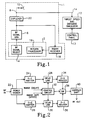
- FIG. 1 presents a summary block diagram of the new target speed and distance simulator connected to a radar system 1.
- the radar system processor includes a computer 2 that selects the characteristics of the radar RF signal to be transmitted; this function is indicated by block 4.
- the desired signal is produced by an RF signal generator 6 and delivered via a duplexer 20 and line 8 to an antenna 10, which typically will also provide a reception in a radar transceiver system.
- the target speed and distance simulator system of the present invention is indicated by block 12.
- An input line 14 can tap the RF signal on line 8 and deliver at least a portion of that signal to the simulator system.
- a sample from the radar for input line 14 could also be obtained from several other places, such as the output of antenna 10 or elsewhere within a typical radar system.
- This system block 12 produces a controlled initial delay signal that simulates a target distance from the radar set, and periodically updates the delay at a controlled rate to simulate a target speed relative to the radar set based on an input from simulator operator control panel 13.
- These simulation parameters are typically provided by a computer that is part of the simulator and that is set up by the front panel 13 set of controls.
- the delayed signal output from the simulator is delivered back to the radar system, which processes this "ideal" signal as if it were real to determine the simulated target speed, range and other typical radar parameters.
- the signal returned to the radar can be connected back to the radar receiver 18 either via the radar duplexer 20 or by radiating into antenna 10. From the return receiver 18 the signal is delivered to a return processor 16 that decodes the signal to calculate the simulated target speed and range.
- the return processor 16 can conveniently be implemented by the computer 2 that is already resident in the radar processor system.
- Typical modern airborne radar can have a long range (up to about 80 nautical miles) and high resolution (about 25 feet) capability. This translates into a simulator signal delay requirement of up to about 1,000 microseconds to simulate this maximum radar range. To adequately test radar range resolution, and to smoothly simulate target motion, this delay must be changeable in increments as small as 50 nanoseconds.
- the present invention uses optical fibers, which have a wide bandwidth and extremely low optical loss (about 0.2 db/km), to achieve this range of delays.
- the basic approach is to convert a sample of the radar transmitted signal into an amplitude modulated light wave, which is then transmitted through a programmed length of optical fiber to produce the desired time delay.
- the modulated light signal is demodulated at the end of the fiber and, after shifting the output electrical signal by the proper Doppler frequency shift, a simulated radar return signal is obtained that can be used to evaluate the end-to-end performance of the entire radar.
- This use of the radar as its own tester by returning a delayed ideal replica simulated target is an excellent way to evaluate radar system end-to-end (total) performance.
- Other types of radars with different parameters of range, range rate and range resolution capability can also be simulated by designing a simulator with different parameters then the typical values stated above.
- FIG. 2 A block diagram of the present simulator 12 in FIG. 1 is provided in FIG. 2.
- the signal from the radar in FIG. 1 is split by an RF power divider 22, and each divided portion is used to modulate respective low noise opto-electronic transmitters 24 and 26.
- the opto-electronic transmitters can be directly modulated lasers or external modulators. While two opto-electronic transmitters and corresponding delay lines are shown in FIG. 2, the system could be expanded to incorporate three or more separate delay lines if desired. Instead of dividing the input RF signal, it could be used to modulate a single opto-electronic transmitter, with the transmitter output then split between the various delay lines with an optical splitter.
- Each opto-electronic transmitter 24,26 transmits an RF-modulated optical beam to corresponding fiber optic delay lines 28,30.
- the delay which these lines add to their respective optical signals is controlled by the computer in the simulator 12 via appropriate control interface circuitry 32.
- the delayed optical outputs from the delay lines 28,30 are converted to electrical signals by opto-electric transducers 34,36, respectively, which are preferably implemented as photodiodes.
- the electrical outputs from transducers 34 and 36 are presented to a conventional RF switch 38 that selects the signal from only one line at a time. Optical switching means could also be used if they have fast switching times.
- the signals presented to the switch can be from DC through the microwave frequency range (from about 100 MHz to 100 GHz), depending upon the capability of the photonic components used.
- the operation of switch 38 is controlled by the computer in the simulator 12, via control interface 32.
- the second line's delay is thus provided as the output for the overall simulator.
- the first line is reprogrammed with a new delay period.
- the switch is actuated by the simulator computer to disconnect from the second delay line and connect to the first delay line, thus changing the simulator's output delay to the newly programmed delay of the first line.
- the second delay line which is disconnected from the delay output at this time, can now be reprogrammed with a new delay period of its own.
- the switch 38 continues to alternate between the two delay lines, with the disconnected delay line reprogrammed while the other delay line provides the simulator output. In this fashion an almost constant output is produced from the simulator, with a rapid updating capability.
- the switching between delay lines also allows the line to be emptied and reloaded with new data pulses.
- the maximum switching rate between lines is determined by the optical switch settling time or the line load time for new pulses, whichever is longer; this maximum switching rate along with the delay line range resolution determines the maximum closing target speed that can be simulated.
- a conventional RF switch 38 is capable of operating at speeds of up to about 100-200 MHz. However, it requires about 6 msec to reprogram the fiber optic delay lines, including settling time for a reprogram delay.
- the operation of switch 38 is synchronized with the reprogramming of the multiple delay lines 28,30, and is thus operated at a rate far below its capacity. The dead time during which no useable signal is produced by the simulator is thus reduced to a very low level that is determined by the switching time of the high speed RF switch 38, which can be as low as a few nanoseconds.
- a Doppler frequency shift circuit 40 of conventional design is connected to the output of switch 38.
- the addition of a Doppler shift to the radar signal delay provides a complete simulation of a target moving either towards or away from the radar set.
- both the target speed (operator selectable) and radar radiated frequency (not necessarily known) must be utilized.
- the radar frequency is measured by a commercial unit so that it does not have to be sent from the radar as a data input, and thus the test set can be independent of radar control signals; this is a desired feature of this test target simulator.
- An additional fiber optic delay line at the input to the simulator not shown in FIG. 2, is used to delay the input signal long enough for the external (to radar) commercial frequency measuring unit to measure the radar frequency and set up the correct Doppler shift for the frequency of the delay line output.
- the two delay lines 28 and 30 are preferably identical.
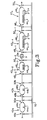
- a preferred structure for each delay line is shown in FIG. 3.
- the delay line is broken into a series of individual fiber optic delay segments 42 a , 42 b ,...42 n-2 , 42 n-1 , 42 n , where n in the total number of delay segments.
- Each segment consists of a coiled length of optical fiber 44 a , 44 b , etc., and a short adjacent length of optical fiber 46 a , 46 b , etc. whose length produces a negligible delay.
- the coiled length and negligible delay length form two selectable signal paths, and a switch on each end can be used to switch between them.
- the lengths of the optical fiber coils preferably form a binary sequence in the form L times 2 k , where L is a unit of optical fiber delay in the coiled segment and is given in seconds, and k is the order of a given fiber segment.
- the segments accordingly provide respective delay times of L times 2 k seconds each. If T is the total number of binary segments, then the total line length is 2 T -1 times L seconds.
- 14 segments are used, with the first 13 segments arranged in a binary progression and the length of the 14th segment equal to that of the 13th. To obtain a simulated range of up to 80 nautical miles and a range resolution of 42 feet the length of the first segment 44 a is 17m, which produces a delay in the fiber optic cable of about 83 nsec.
- This length increases up to the 13th segment 44 n-1 , which is about 70 km long. With the final segment 44 n also about 70 km, the total length of the delay line when all of the segments are connected together in series is about 208 km; this provides an upper limit delay of about 1 millisecond, which corresponds to a maximum radar range of about 80 nautical miles.
- switches 48 a , 48 b ,...48 n-2 , 48 n-1 , 48 n are provided at the input end of each delay segment, while similar switches 50 a , 50 b ,...50 n-2 , 50 n-1 , 50 n are provided at the output of each delay segment.
- the switches 48 and 50 are connected to select between their respective delay lines 44 a , 44 b , etc. and the optical bypasses to those lines 46 a , 46 b , etc. for inclusion in an aggregate delay line. Control over the various switches is provided from the control interface 32 over a control interface bus 52.
- a desired overall delay is implemented by selecting individual segments whose total delay adds up to the desired amount, switching the segments into the aggregate delay line, and switching in the bypasses for the other segments into the aggregate line.
- the delay period is reprogrammed by altering the switching pattern so that a new combination of delay segments, whose individual delays total to the new desired overall delay, are included in the aggregate delay line.
- electro-mechanical switches While fast operating electro-optic devices could be used for the switches 48 and 50, these devices also have high insertion losses. It is therefore desirable to use electro-mechanical switches, which have relatively low insertion losses. Electro-mechanical switches, however, also have considerably lower switching speeds than electro-optic switches.
- the parallel programmable delay line architecture of the present invention permits the use of electro-mechanical switches without limiting the overall simulator to their relatively slow switching speeds.
- in-line fiber optic amplifiers 54 may be employed. Such amplifiers are preferably of the erbium-doped type, which are characterized by low noise, high gain and polarization insensitivity. For the shorter segments it is generally sufficient to locate an amplifier between a pair of adjacent segments, while for the longer segments such as 42 n-1 , 42 n it may be desirable to integrate an amplifier in with the segment.
- the amplifiers 54 are pumped with respective pump lasers p. For economy, a high power laser can be used with a power divider to pump the several amplifiers 54.
Landscapes
- Engineering & Computer Science (AREA)
- Computer Networks & Wireless Communication (AREA)
- Physics & Mathematics (AREA)
- General Physics & Mathematics (AREA)
- Radar, Positioning & Navigation (AREA)
- Remote Sensing (AREA)
- Optical Radar Systems And Details Thereof (AREA)
- Radar Systems Or Details Thereof (AREA)
- Light Guides In General And Applications Therefor (AREA)
- Monitoring And Testing Of Transmission In General (AREA)
Abstract
Description
- The present invention relates to a programmable fiber optic delay system and to a radar target speed and distance simulation system using the programmable fiber optic delay system.
- U.S. patent 4 671 605 discloses a length-dependent optical time delay device for electrical signals. The device comprises two optical time delay components each made up of a plurality of parallel optical fibers of varying length. Each one fiber of the first and the second group thereof can be connected in series in order to delay an optical signal, respectively. To this end, each two switches of the 8:1 and 1:8 type are provided, respectively. At the input of each group or time delay component, a 1:8 selector is provided and at the output of each group an 8:1 selector is necessary. These selectors or switches are part of an integrated circuit and are being controlled by a variable voltage source.
- Each of the optical fibers of the time delay components is increased in length with respect to an adjacent fiber by the same amount, so that this differential length gives the resolution of this system. By this arrangement, the maximum delay is limited to N-times differential delay, whereby N is the number of parallel fibers in each group.
- International patent application WO-A-89/08854 discloses a radar target simulation system which produces a replica of the radar signal substantially delayed in time. To this end, the radar signal modulates a laser light which is controllable delayed in time by transmitting the modulated laser light through a fiber optic delay line. The output of the delay line is demodulated and the delayed radar signal is returned to the radar as a test signal. The fiber optic delay line comprises one fiber optic cable, the amount of achieved time delay being direct proportional to the length of this fiber optic cable.
- U.S. patent 4 028 702 discloses a fiber optic delay line comprising a plurality of fiber optic segments connected in series by optical switches. Each segment has an associated segment with a relatively negligible delay wherein the optical switches select for each of the delay segments between said delay segment and said associated negligible delay segment for inclusion in the delay line.
- Modern radar systems employ complex waveforms and need to have their performance completely tested (from end to end) Under controlled conditions. Test systems used to simulate a moving target are generally designed to return a copy or simulated copy of a transmitted radar pulse, after delaying or simulating the delay of the pulse by a period of time corresponding to the round-trip transit time to the target, with the addition of an expected Doppler frequency shift. The delay parameters are updated at regular intervals, corresponding to the target velocity and the desired range resolution, to simulate target movement.
- The general approach to testing using delayed transmitted radar pulses has been to put a large target (such as a corner reflector or repeater) out at a distance from the radar so that a long delay is achieved because of the round trip time to this simulated target. This technique suffers from the fact that the radar signal is perturbed by the outside environment that is not under the control of the tester, and has several undesirable features. Excessive losses at radio frequency (RF) rule out the feasibility of using coaxial cables to provide long delay times. Surface acoustic wave delay lines are also lossy, with a limited RF bandwidth and delay time capability. Simulated target generators for radar testing can employ digital RF memory (DRFM) to simulate a moving target. Such a system employs sampling and analog-to-digital conversion techniques to store sampled waveform data of the transmitted radar pulses. However, DRFM introduces undesired frequency spurs (spectral impurities), has a reduced dynamic range and bandwidth because of the need for analog-to-digital conversion, and requires complex circuitry that has a relatively high power consumption. Also an RF target generator system can generate a simulated delayed radar pulse by using reference signals from the radar to generate the pulse in the same way the radar generates the signal that goes to the radar transmitter.
- A recirculating fiber optic delay line/memory has also been proposed in P.R. Herczfeld, I. Koffman, A.S. Daryoush, R. Saedi, B. Even-Or and R. Markowitz, "A Fiberoptic Recirculating Delay Line", Proc. SPIE, Vol. 996, pp. 116-123 (1988). In this type of system the RF signal circulates repeatedly around a fiber optic loop, and is tapped off after the desired delay period. Although it employs a regenerative process to overcome losses, the noise buildup associated with the regeneration limits the number of recirculations and the technique needs perfecting.
- A fixed fiber optic delay line is described in U.S. patent 4 903 029 to Newberg et al. While this is a low loss delay mechanism, it encorporates a fixed delay that cannot be adjusted, and therefore can be used to simulate only a fixed target distance without any target movement.
- In view of the above it is an object of the present invention to provide a programmable fiber optic delay system and a respective radar test target simulator using the new programmable fiber optic delay system that can provide real time delay.
- According to the invention this object is achieved with a programmable fiber optic delay system, comprising:
- a plurality of fiber optic delay lines, each delay line having a programmable delay period and a plurality of fiber optic segments having predetermined optical delays, wherein said segments are switchable into said delay line in series,
- coordinating means for programming said delay lines with respective series of delays by switching desired segments into each delay line,
- switching means for switching among said plurality of delay lines for inclusion in a delay path, and
- said coordination means for coordinating said switching means with the programming of said delay lines, so that only a delay line with a settled delay program is included in said delay path.
- Further, this object is achieved with a radar target speed and distance simulation system, comprising:
- a) a radar processor for generating a radar signal,
- b) means for converting said radar signal into a corresponding optical signal,
- c) a fiber optic delay system for delaying said optical signal by a time period corresponding to a simulated target distance, and
- d) means for supplying a signal which incorporates the delay of said delay path back to said radar processor as a simulated target distance,
- The present invention seeks to provide a programmable signal delay mechanism for a radar test target simulator that can provide real time delay of the actual radar transmitted pulses and simulate long target distances, without excessive losses or corruption from outside environment while being located adjacent to the radar, and yet has both fine delay resolution and long delay times so that it can simulate a broad range of distances and target speeds. A relatively wide RF bandwidth, the avoidance of undue complexity and low noise levels are further goals of the invention. Also, the simulation of an ideal target signal return to the radar is achieved without or with only a minimum number of control signals from the radar. This is a unique and desired capability of a test set that is not provided by other types of target simulators.
- The new radar target speed and distance simulation system employs a minimum of two optical fiber delay lines. At any given time, only one of these lines is being used to provide the delay. This line, the active line, has the correct length for the distance being simulated. While this active line is being used, the inactive line(s) are being reconfigured for new simulated distances. This reconfiguration consists of changing the line length by switching in or out incremental lengths of line, flushing the unwanted information out of the line, allowing the mechanical switching transients to decay, and reloading the line with a properly sequenced signal. At the appropriate time this properly prepared second line is selected to provide the delay, and the first line becomes inactive. Because line selection is performed with a very high speed optical or microwave switch, the flow of data is essentially uninterrupted.
- Each delay line includes a plurality of fiber optic segments having predetermined optical delays, and a switching scheme for connecting into an aggregate delay line only those segments which accumulate to the desired delay. In the preferred embodiment different segments have different lengths and correspondingly different delay periods, and are arranged in a binary progression. The selected segments are switched into the aggregate delay line; optical bypasses are switched into the aggregate delay line for the undesired segments. Optical amplifiers are incorporated into the overall delay line to compensate for losses; the amplifiers are preferably located between adjacent segments of shorter length, and within segments of longer length.
- A computer can be used to program the individual delay lines and control the switching among those lines. The output radar signal is sampled by either direct coupling or via an antenna to receive some of the radar's radiation, and modulated onto the optical signal of the opto-electronic transmitter for processing through the optical delay system. The output of that system is converted back to an electrical signal that is a nearly ideal replica of the radar's transmitted signal and fed back to the radar as a simulated radar target at a selected range (delay) and speed (velocity).
- The multi-line approach allows one to use relatively slow mechano-optical or thermo-optical switches to change the length of the inactive line, while maintaining an uninterrupted flow of delayed signal through the active line. Mechano-optical switches have low loss and low crosstalk, properties that are necessary for ultra-long, high-resolution programmable delay lines. The two-line approach also allows one to unambiguously remove "incorrect" information from the line, and to reload it with correct information (i.e., a properly sequenced signal train). Proper sequencing is essential for accurate replication of radar echoes.
- These and other features and advantages of the invention will be apparent to those skilled in the art from the following detailed description, taken together with the accompanying drawings, in which:
- FIG. 1 is a block diagram of a radar target speed and distance simulation system in accordance with the invention;
- FIG. 2 is a block diagram of the multiple optical delay line speed and distance simulator; and
- FIG. 3 is a schematic diagram of one of the optical delay lines incorporated in the overall simulator.
- FIG. 1 presents a summary block diagram of the new target speed and distance simulator connected to a
radar system 1. The radar system processor includes acomputer 2 that selects the characteristics of the radar RF signal to be transmitted; this function is indicated by block 4. The desired signal is produced by anRF signal generator 6 and delivered via aduplexer 20 and line 8 to anantenna 10, which typically will also provide a reception in a radar transceiver system. - The target speed and distance simulator system of the present invention is indicated by
block 12. An input line 14 can tap the RF signal on line 8 and deliver at least a portion of that signal to the simulator system. A sample from the radar for input line 14 could also be obtained from several other places, such as the output ofantenna 10 or elsewhere within a typical radar system. Thissystem block 12 produces a controlled initial delay signal that simulates a target distance from the radar set, and periodically updates the delay at a controlled rate to simulate a target speed relative to the radar set based on an input from simulator operator control panel 13. These simulation parameters are typically provided by a computer that is part of the simulator and that is set up by the front panel 13 set of controls. The delayed signal output from the simulator is delivered back to the radar system, which processes this "ideal" signal as if it were real to determine the simulated target speed, range and other typical radar parameters. The signal returned to the radar can be connected back to the radar receiver 18 either via theradar duplexer 20 or by radiating intoantenna 10. From the return receiver 18 the signal is delivered to areturn processor 16 that decodes the signal to calculate the simulated target speed and range. Thereturn processor 16 can conveniently be implemented by thecomputer 2 that is already resident in the radar processor system. - Typical modern airborne radar can have a long range (up to about 80 nautical miles) and high resolution (about 25 feet) capability. This translates into a simulator signal delay requirement of up to about 1,000 microseconds to simulate this maximum radar range. To adequately test radar range resolution, and to smoothly simulate target motion, this delay must be changeable in increments as small as 50 nanoseconds.
- The present invention uses optical fibers, which have a wide bandwidth and extremely low optical loss (about 0.2 db/km), to achieve this range of delays. The basic approach is to convert a sample of the radar transmitted signal into an amplitude modulated light wave, which is then transmitted through a programmed length of optical fiber to produce the desired time delay. The modulated light signal is demodulated at the end of the fiber and, after shifting the output electrical signal by the proper Doppler frequency shift, a simulated radar return signal is obtained that can be used to evaluate the end-to-end performance of the entire radar. This use of the radar as its own tester by returning a delayed ideal replica simulated target is an excellent way to evaluate radar system end-to-end (total) performance. Other types of radars with different parameters of range, range rate and range resolution capability can also be simulated by designing a simulator with different parameters then the typical values stated above.
- A block diagram of the
present simulator 12 in FIG. 1 is provided in FIG. 2. The signal from the radar in FIG. 1 is split by anRF power divider 22, and each divided portion is used to modulate respective low noise opto-electronic transmitters 24 and 26. The opto-electronic transmitters can be directly modulated lasers or external modulators. While two opto-electronic transmitters and corresponding delay lines are shown in FIG. 2, the system could be expanded to incorporate three or more separate delay lines if desired. Instead of dividing the input RF signal, it could be used to modulate a single opto-electronic transmitter, with the transmitter output then split between the various delay lines with an optical splitter. - Each opto-electronic transmitter 24,26 transmits an RF-modulated optical beam to corresponding fiber
optic delay lines simulator 12 via appropriatecontrol interface circuitry 32. - The delayed optical outputs from the
delay lines electric transducers transducers conventional RF switch 38 that selects the signal from only one line at a time. Optical switching means could also be used if they have fast switching times. The signals presented to the switch can be from DC through the microwave frequency range (from about 100 MHz to 100 GHz), depending upon the capability of the photonic components used. The operation ofswitch 38 is controlled by the computer in thesimulator 12, viacontrol interface 32. While a first delay line is being programmed with a desired delay period, and during the settling time for this programmed line, theswitch 38 connects the second line (which already has a settled programmed delay), to the simulator output. The second line's delay is thus provided as the output for the overall simulator. To vary the delay period, the first line is reprogrammed with a new delay period. Once the first line has settled at its new delay, the switch is actuated by the simulator computer to disconnect from the second delay line and connect to the first delay line, thus changing the simulator's output delay to the newly programmed delay of the first line. The second delay line, which is disconnected from the delay output at this time, can now be reprogrammed with a new delay period of its own. Theswitch 38 continues to alternate between the two delay lines, with the disconnected delay line reprogrammed while the other delay line provides the simulator output. In this fashion an almost constant output is produced from the simulator, with a rapid updating capability. In addition to allowing settling time for the optical switches, the switching between delay lines also allows the line to be emptied and reloaded with new data pulses. Thus the maximum switching rate between lines is determined by the optical switch settling time or the line load time for new pulses, whichever is longer; this maximum switching rate along with the delay line range resolution determines the maximum closing target speed that can be simulated. - A
conventional RF switch 38 is capable of operating at speeds of up to about 100-200 MHz. However, it requires about 6 msec to reprogram the fiber optic delay lines, including settling time for a reprogram delay. The operation ofswitch 38 is synchronized with the reprogramming of themultiple delay lines speed RF switch 38, which can be as low as a few nanoseconds. - A Doppler
frequency shift circuit 40 of conventional design is connected to the output ofswitch 38. The addition of a Doppler shift to the radar signal delay provides a complete simulation of a target moving either towards or away from the radar set. To add the correct Doppler shift to the target, both the target speed (operator selectable) and radar radiated frequency (not necessarily known) must be utilized. In this test set the radar frequency is measured by a commercial unit so that it does not have to be sent from the radar as a data input, and thus the test set can be independent of radar control signals; this is a desired feature of this test target simulator. An additional fiber optic delay line at the input to the simulator, not shown in FIG. 2, is used to delay the input signal long enough for the external (to radar) commercial frequency measuring unit to measure the radar frequency and set up the correct Doppler shift for the frequency of the delay line output. - The two
delay lines optic delay segments optical fiber form L times 2k, where L is a unit of optical fiber delay in the coiled segment and is given in seconds, and k is the order of a given fiber segment. The segments accordingly provide respective delay times ofL times 2k seconds each. If T is the total number of binary segments, then the total line length is 2T-1 times L seconds. In the preferred embodiment 14 segments are used, with the first 13 segments arranged in a binary progression and the length of the 14th segment equal to that of the 13th. To obtain a simulated range of up to 80 nautical miles and a range resolution of 42 feet the length of thefirst segment 44a is 17m, which produces a delay in the fiber optic cable of about 83 nsec. This length increases up to the13th segment 44n-1, which is about 70 km long. With thefinal segment 44n also about 70 km, the total length of the delay line when all of the segments are connected together in series is about 208 km; this provides an upper limit delay of about 1 millisecond, which corresponds to a maximum radar range of about 80 nautical miles. - 1x2 switches 48a, 48b,...48n-2, 48n-1, 48n are provided at the input end of each delay segment, while similar switches 50a, 50b,...50n-2, 50n-1, 50n are provided at the output of each delay segment. The switches 48 and 50 are connected to select between their
respective delay lines control interface 32 over acontrol interface bus 52. - A desired overall delay is implemented by selecting individual segments whose total delay adds up to the desired amount, switching the segments into the aggregate delay line, and switching in the bypasses for the other segments into the aggregate line. The delay period is reprogrammed by altering the switching pattern so that a new combination of delay segments, whose individual delays total to the new desired overall delay, are included in the aggregate delay line.
- While fast operating electro-optic devices could be used for the switches 48 and 50, these devices also have high insertion losses. It is therefore desirable to use electro-mechanical switches, which have relatively low insertion losses. Electro-mechanical switches, however, also have considerably lower switching speeds than electro-optic switches. The parallel programmable delay line architecture of the present invention permits the use of electro-mechanical switches without limiting the overall simulator to their relatively slow switching speeds.
- Although the losses associated with optical fibers are very low on a per unit length basis, the long aggregate length of the various optical fiber segments can result in appreciable cumulative losses. To compensate for such losses, in-line
fiber optic amplifiers 54 may be employed. Such amplifiers are preferably of the erbium-doped type, which are characterized by low noise, high gain and polarization insensitivity. For the shorter segments it is generally sufficient to locate an amplifier between a pair of adjacent segments, while for the longer segments such as 42n-1, 42n it may be desirable to integrate an amplifier in with the segment. Theamplifiers 54 are pumped with respective pump lasers p. For economy, a high power laser can be used with a power divider to pump theseveral amplifiers 54.
Claims (14)
- A programmable fiber optic delay system, comprising:a plurality of fiber optic delay lines (28, 30), each delay line (28, 30) having a programmable delay period and a plurality of fiber optic segments (44) having predetermined optical delays, wherein said segments (44) are switchable into said delay line (28, 30) in series,coordinating means (32) for programming said delay lines (28, 30) with respective series of delays by switching desired segments (44) into each delay line (28, 30),switching means (38) for switching among said plurality of delay lines (28, 30) for inclusion in a delay path, andsaid coordinating means (32) for coordinating said switching means (38) with the programming of said delay lines (28, 30), so that only a delay line (28, 30) with a settled delay program is included in said delay path.
- The programmable fiber optic delay system of claim 1, characterized in that said coordinating means (32) comprise means for varying the switching rate among said delay lines (28, 30).
- The programmable fiber optic delay system of claim 1, further characterized by means (24, 26) associated with each delay line (28, 30) for generating optical signals for transmission along their respective delay lines (28, 30) in response to a radio frequency (RF) input signal, and means (34, 36) for converting said optical signals back to an RF output signal.
- The programmable fiber optic delay system of claim 1, characterized in that each delay line (28, 30) further comprises an opto-electric transducer (34, 36) for converting its delayed optical signal to an electrical signal, said switching means (38) selecting among said electrical signals for inclusion in said delay path.
- The programmable fiber optic delay system of claim 1, characterized in that for each delay line (28, 30) at least some of said segments (44) have different lengths with correspondingly different delays.
- The programmable fiber optic delay system of claim 1, characterized in that further switching means (48, 50) are provided for switching said segments (44) into said delay lines (28, 30).
- The programmable fiber optic delay system of claim 6, characterized in that for each delay line (28, 30) at least some of said segments (44) comprise a binary progression of respective lengths and delay times.
- The programmable fiber optic delay system of claim 6, characterized in that for each delay line (28, 30) each of said segments (44) has an associated fiber optic segment (46) with a relativly negligible delay, said further switching means (48, 50) selecting between each of said delay segments and their associated negligible delay segments (46) for inclusion in said series delay line (28, 30).
- The programmable fiber optic delay system of claim 1, characterized by a plurality of optical amplifiers (54) in said delay line (28, 30).
- The programmable fiber optic delay system of claim 9, characterized in that some of said optical amplifiers (54) are located between adjacent segments (44n-2, 44n-1), and some are located within a segment (44n).
- The programmable fiber optic delay system of claim 9, said segments (44) having a plurality of different lengths with correspondingly different delays, characterized in that at least some of said optical amplifiers (54) are located between adjacent segments (44n-2, 44n-1) of shorter length, and at least some are located within a segment (44n) of longer length.
- A radar target speed and distance simulation system, comprising:a) a radar processor (2, 6) for generating a radar signal,b) means (24, 26) for converting said radar signal into a corresponding optical signal,c) a fiber optic delay system (28 - 38) for delaying said optical signal by a time period corresponding to a simulated target distance, andd) means (18) for supplying a signal which incorporates the delay of said delay path back to said radar processor (2) as a simulated target distance,wherein said fiber optic delay system (28 - 38) is the programmable fiber optic delay system (28 - 38) of any of claims 1 - 11, whereby said series of delays correspond to a simulated speed of target movement.
- The radar target speed and distance simulation system of claim 12, characterized in that a control computer is programmed and connected to provide said delay line programming and said coordination of said switching means (38) with said delay line programming.
- The radar target speed and distance simulation system of claim 12, characterized in that said signal supplying means (18) includes means for converting the delayed optical signal to a radio frequency (RF) radar target signal.
Applications Claiming Priority (3)
| Application Number | Priority Date | Filing Date | Title |
|---|---|---|---|
| US773187 | 1991-10-08 | ||
| US07/773,187 US5177488A (en) | 1991-10-08 | 1991-10-08 | Programmable fiber optic delay line, and radar target simulation system incorporating the same |
| PCT/US1992/008224 WO1993007508A1 (en) | 1991-10-08 | 1992-09-25 | Programmable fiber optic delay line, and radar target simulation system incorporating the same |
Publications (2)
| Publication Number | Publication Date |
|---|---|
| EP0565663A1 EP0565663A1 (en) | 1993-10-20 |
| EP0565663B1 true EP0565663B1 (en) | 1997-07-23 |
Family
ID=25097473
Family Applications (1)
| Application Number | Title | Priority Date | Filing Date |
|---|---|---|---|
| EP92921408A Expired - Lifetime EP0565663B1 (en) | 1991-10-08 | 1992-09-25 | Programmable fiber optic delay line, and radar target simulation system incorporating the same |
Country Status (6)
| Country | Link |
|---|---|
| US (1) | US5177488A (en) |
| EP (1) | EP0565663B1 (en) |
| JP (1) | JPH06507028A (en) |
| DE (1) | DE69221121T2 (en) |
| IL (1) | IL103344A (en) |
| WO (1) | WO1993007508A1 (en) |
Cited By (1)
| Publication number | Priority date | Publication date | Assignee | Title |
|---|---|---|---|---|
| CN109459733A (en) * | 2018-10-26 | 2019-03-12 | 中电科仪器仪表有限公司 | Anticollision Radar target velocity simulator, system and method based on pm mode |
Families Citing this family (88)
| Publication number | Priority date | Publication date | Assignee | Title |
|---|---|---|---|---|
| US5300934A (en) * | 1992-08-27 | 1994-04-05 | Fieldtech Avionics & Instruments, Inc. | Radar altimeter loop simulator |
| US5262786A (en) * | 1992-10-07 | 1993-11-16 | Westinghouse Electric Corp. | Radar test instrument using optical delay means |
| US5329118A (en) * | 1992-12-23 | 1994-07-12 | Riza Nabeel A | Optical transversal filter |
| US5339087A (en) * | 1993-10-27 | 1994-08-16 | The United States Of America As Represented By The Secretary Of The Navy | Wavefront simulator for evaluating RF communication array signal processors |
| US5786922A (en) * | 1996-02-15 | 1998-07-28 | Honeywell Inc. | Dual signal subharmonic carrier for systems with unknown delay |
| KR100269182B1 (en) * | 1997-07-29 | 2000-11-01 | 박태진 | Beacon apparatus in radar system |
| US6067041A (en) * | 1998-10-15 | 2000-05-23 | Northrop Grumman Corporation | Moving target simulator |
| FR2787588B1 (en) * | 1998-12-18 | 2001-03-16 | Thomson Csf | LIDAR SYSTEM AND APPLICATION TO A RADAR SYSTEM |
| US6346909B1 (en) * | 2000-09-06 | 2002-02-12 | The United States Of America As Represented By The Secretary Of The Army | System for generating simulated radar targets |
| ATE454845T1 (en) | 2000-10-30 | 2010-01-15 | Gen Hospital Corp | OPTICAL SYSTEMS FOR TISSUE ANALYSIS |
| US6933883B2 (en) * | 2001-02-08 | 2005-08-23 | Fujitsu Ten Limited | Method and device for aligning radar mount direction, and radar aligned by the method or device |
| WO2002080410A2 (en) * | 2001-03-30 | 2002-10-10 | Corning Incorporated | Optical transmission line |
| GB0113766D0 (en) * | 2001-05-31 | 2003-02-26 | Bae Systems Plc | Improvements relating to optical delay lines |
| US7313635B1 (en) * | 2002-03-21 | 2007-12-25 | Cisco Technology | Method and apparatus for simulating a load on an application server in a network |
| RU2213421C1 (en) * | 2002-06-21 | 2003-09-27 | Южно-Российский государственный университет экономики и сервиса | Dynamic radio-signal memory device |
| US7145504B1 (en) * | 2004-03-11 | 2006-12-05 | Raytheon Company | Arbitrary radar target synthesizer (arts) |
| AU2005270037B2 (en) | 2004-07-02 | 2012-02-09 | The General Hospital Corporation | Endoscopic imaging probe comprising dual clad fibre |
| JP5324095B2 (en) | 2004-08-24 | 2013-10-23 | ザ ジェネラル ホスピタル コーポレイション | Method and apparatus for imaging blood vessel segments |
| WO2006058346A1 (en) * | 2004-11-29 | 2006-06-01 | The General Hospital Corporation | Arrangements, devices, endoscopes, catheters and methods for performing optical imaging by simultaneously illuminating and detecting multiple points on a sample |
| KR20080013919A (en) * | 2005-04-22 | 2008-02-13 | 더 제너럴 하스피탈 코포레이션 | Apparatus, Systems and Methods for Providing Spectral Domain Polarization Sensitive Optical Coherence Tomography |
| EP2325803A1 (en) | 2005-04-28 | 2011-05-25 | The General Hospital Corporation | Evaluating optical coherence tomography information for an anatomical structure |
| EP1889037A2 (en) * | 2005-06-01 | 2008-02-20 | The General Hospital Corporation | Apparatus, method and system for performing phase-resolved optical frequency domain imaging |
| DE602006017558D1 (en) * | 2005-08-09 | 2010-11-25 | Gen Hospital Corp | DEVICE AND METHOD FOR CARRYING OUT POLARIZATION-BASED QUADRATURE DEMODULATION IN OPTICAL COHERENCE TOMOGRAPHY |
| WO2007022220A2 (en) * | 2005-08-16 | 2007-02-22 | The General Hospital Corporation | Arrangements and methods for imaging in vessels |
| EP1940286A1 (en) * | 2005-09-29 | 2008-07-09 | General Hospital Corporation | Method and apparatus for method for viewing and analyzing of one or more biological samples with progressively increasing resolutions |
| WO2007084903A2 (en) | 2006-01-19 | 2007-07-26 | The General Hospital Corporation | Apparatus for obtaining information for a structure using spectrally-encoded endoscopy techniques and method for producing one or more optical arrangements |
| US20080002211A1 (en) * | 2006-01-20 | 2008-01-03 | The General Hospital Corporation | System, arrangement and process for providing speckle reductions using a wave front modulation for optical coherence tomography |
| US9186066B2 (en) | 2006-02-01 | 2015-11-17 | The General Hospital Corporation | Apparatus for applying a plurality of electro-magnetic radiations to a sample |
| US10426548B2 (en) | 2006-02-01 | 2019-10-01 | The General Hosppital Corporation | Methods and systems for providing electromagnetic radiation to at least one portion of a sample using conformal laser therapy procedures |
| JP2009527770A (en) | 2006-02-24 | 2009-07-30 | ザ ジェネラル ホスピタル コーポレイション | Method and system for performing angle-resolved Fourier domain optical coherence tomography |
| US7801447B1 (en) * | 2006-02-28 | 2010-09-21 | Lockheed Martin Corporation | Method and system for signal processing by modulation of an optical signal with a multichannel radio frequency signal |
| EP3150110B1 (en) | 2006-05-10 | 2020-09-02 | The General Hospital Corporation | Processes, arrangements and systems for providing frequency domain imaging of a sample |
| WO2008049118A2 (en) | 2006-10-19 | 2008-04-24 | The General Hospital Corporation | Apparatus and method for obtaining and providing imaging information associated with at least one portion of a sample and effecting such portion(s) |
| US7724179B2 (en) * | 2007-02-07 | 2010-05-25 | Lockheed Martin Corporation | Miniaturized microwave-photonic receiver |
| US7782250B2 (en) * | 2008-06-13 | 2010-08-24 | Honeywell International Inc. | Millimeter wave radar target simulation systems and methods |
| WO2010009136A2 (en) | 2008-07-14 | 2010-01-21 | The General Hospital Corporation | Apparatus and methods for color endoscopy |
| EP2324390A1 (en) * | 2008-09-18 | 2011-05-25 | Selex Sistemi Integrati S.P.A. | Switchable delays optical fibre transponder with optical generation of doppler shift |
| WO2010090837A2 (en) | 2009-01-20 | 2010-08-12 | The General Hospital Corporation | Endoscopic biopsy apparatus, system and method |
| US9178330B2 (en) * | 2009-02-04 | 2015-11-03 | The General Hospital Corporation | Apparatus and method for utilization of a high-speed optical wavelength tuning source |
| BR112012001042A2 (en) | 2009-07-14 | 2016-11-22 | Gen Hospital Corp | fluid flow measurement equipment and method within anatomical structure. |
| GB2474863A (en) * | 2009-10-28 | 2011-05-04 | Univ Gent | Optical buffer with controllable delay |
| EP2542145B1 (en) | 2010-03-05 | 2020-08-12 | The General Hospital Corporation | Systems which provide microscopic images of at least one anatomical structure at a particular resolution |
| US9069130B2 (en) | 2010-05-03 | 2015-06-30 | The General Hospital Corporation | Apparatus, method and system for generating optical radiation from biological gain media |
| US9795301B2 (en) | 2010-05-25 | 2017-10-24 | The General Hospital Corporation | Apparatus, systems, methods and computer-accessible medium for spectral analysis of optical coherence tomography images |
| EP2575597B1 (en) | 2010-05-25 | 2022-05-04 | The General Hospital Corporation | Apparatus for providing optical imaging of structures and compositions |
| WO2011153434A2 (en) | 2010-06-03 | 2011-12-08 | The General Hospital Corporation | Apparatus and method for devices for imaging structures in or at one or more luminal organs |
| JP5883018B2 (en) | 2010-10-27 | 2016-03-09 | ザ ジェネラル ホスピタル コーポレイション | Apparatus, system, and method for measuring blood pressure within at least one blood vessel |
| US8452187B2 (en) | 2010-12-02 | 2013-05-28 | Eastern Optx Inc. | Bi-directional, compact, multi-path and free space channel replicator |
| US8248297B1 (en) * | 2011-04-11 | 2012-08-21 | Advanced Testing Technologies, Inc. | Phase noise measurement system and method |
| US8755693B2 (en) * | 2011-05-16 | 2014-06-17 | Eastern Optx, Inc. | Bi-directional, compact, multi-path and free space channel replicator |
| WO2013013049A1 (en) | 2011-07-19 | 2013-01-24 | The General Hospital Corporation | Systems, methods, apparatus and computer-accessible-medium for providing polarization-mode dispersion compensation in optical coherence tomography |
| US9341783B2 (en) | 2011-10-18 | 2016-05-17 | The General Hospital Corporation | Apparatus and methods for producing and/or providing recirculating optical delay(s) |
| US9629528B2 (en) | 2012-03-30 | 2017-04-25 | The General Hospital Corporation | Imaging system, method and distal attachment for multidirectional field of view endoscopy |
| EP2852315A4 (en) | 2012-05-21 | 2016-06-08 | Gen Hospital Corp | APPARATUS, DEVICE AND METHOD FOR CAPSULE MICROSCOPY |
| US9541640B2 (en) * | 2012-08-01 | 2017-01-10 | David R. Hall | Ground penetrating radar with variable dwell time |
| JP6227652B2 (en) | 2012-08-22 | 2017-11-08 | ザ ジェネラル ホスピタル コーポレイション | System, method, and computer-accessible medium for fabricating a miniature endoscope using soft lithography |
| US9968261B2 (en) | 2013-01-28 | 2018-05-15 | The General Hospital Corporation | Apparatus and method for providing diffuse spectroscopy co-registered with optical frequency domain imaging |
| US10893806B2 (en) | 2013-01-29 | 2021-01-19 | The General Hospital Corporation | Apparatus, systems and methods for providing information regarding the aortic valve |
| WO2014121082A1 (en) | 2013-02-01 | 2014-08-07 | The General Hospital Corporation | Objective lens arrangement for confocal endomicroscopy |
| KR101287973B1 (en) * | 2013-03-05 | 2013-07-19 | 국방과학연구소 | Apparatus for checking fmcw(frequency modulated continuous wave) radar |
| WO2014144709A2 (en) | 2013-03-15 | 2014-09-18 | The General Hospital Corporation | Methods and systems for characterizing an object |
| EP2997354A4 (en) | 2013-05-13 | 2017-01-18 | The General Hospital Corporation | Detecting self-interefering fluorescence phase and amplitude |
| EP3021735A4 (en) | 2013-07-19 | 2017-04-19 | The General Hospital Corporation | Determining eye motion by imaging retina. with feedback |
| WO2015009932A1 (en) | 2013-07-19 | 2015-01-22 | The General Hospital Corporation | Imaging apparatus and method which utilizes multidirectional field of view endoscopy |
| WO2015013651A2 (en) | 2013-07-26 | 2015-01-29 | The General Hospital Corporation | System, apparatus and method utilizing optical dispersion for fourier-domain optical coherence tomography |
| WO2015105870A1 (en) | 2014-01-08 | 2015-07-16 | The General Hospital Corporation | Method and apparatus for microscopic imaging |
| US10736494B2 (en) | 2014-01-31 | 2020-08-11 | The General Hospital Corporation | System and method for facilitating manual and/or automatic volumetric imaging with real-time tension or force feedback using a tethered imaging device |
| US10228556B2 (en) | 2014-04-04 | 2019-03-12 | The General Hospital Corporation | Apparatus and method for controlling propagation and/or transmission of electromagnetic radiation in flexible waveguide(s) |
| JP2017525435A (en) | 2014-07-25 | 2017-09-07 | ザ ジェネラル ホスピタル コーポレイション | Apparatus, devices and methods for in vivo imaging and diagnosis |
| AT519539B1 (en) | 2016-12-29 | 2018-10-15 | Avl List Gmbh | Radar target emulator with a crossfade device and method for crossfading signals |
| AT519540B1 (en) | 2016-12-29 | 2018-10-15 | Avl List Gmbh | Switching device for a Radielielemulator and Radarzielemulator with such a switching device |
| AT519538B1 (en) | 2016-12-29 | 2019-05-15 | Avl List Gmbh | Method and system for the simulation-based determination of echo points as well as methods for emulation and emulation device |
| US10509107B2 (en) * | 2017-01-13 | 2019-12-17 | Rohde & Schwarz Gmbh & Co. Kg | Device, system and method for simulating at least one echo signal of an electromagnetic signal |
| US10866308B2 (en) * | 2017-08-03 | 2020-12-15 | Eastern Optx, Inc. | High speed radar test system |
| AT520578B1 (en) | 2017-10-06 | 2021-01-15 | Avl List Gmbh | Device and method for converting a radar signal and test bench |
| CN108490405B (en) * | 2018-03-27 | 2020-10-30 | 中国电子科技集团公司第二十六研究所 | Calibration method for simulation height in target simulator |
| EP3924750B1 (en) | 2019-02-11 | 2024-05-29 | dSPACE GmbH | Testing device for testing a distance sensor that operates using electromagnetic waves |
| CA3150521A1 (en) * | 2019-08-13 | 2021-02-18 | Nanowave Technologies Inc. | Delay device and method of emulating radar signal propagation delays |
| US11520008B2 (en) * | 2019-08-20 | 2022-12-06 | Keysight Technologies, Inc. | Radar target emulation and multi-distance emulation using PMCW radar |
| DE112020003906T5 (en) | 2019-08-20 | 2022-05-05 | Keysight Technologies Inc. | MULTITARGET RADAR EMULATOR SYSTEM |
| US11408992B2 (en) * | 2020-02-12 | 2022-08-09 | Viavi Solutions Inc. | Altimeter testing device and methods |
| EP3879301B1 (en) * | 2020-03-09 | 2025-07-30 | Rohde & Schwarz GmbH & Co. KG | Radar target simulation system and method |
| US11256032B1 (en) * | 2020-12-15 | 2022-02-22 | Dspace Gmbh | Programmable fiber-optic delay line |
| US11867832B2 (en) | 2021-02-15 | 2024-01-09 | Keysight Technologies, Inc. | Separating receive and transmit antennas of a radar test system |
| CN114002774B (en) * | 2021-10-22 | 2023-06-23 | 中国电子科技集团公司第十一研究所 | Optical fiber delay device and long-distance optical signal transmission characteristic simulation method |
| CN114002776B (en) * | 2021-11-04 | 2024-11-08 | 青岛浦芮斯光电技术有限公司 | An adjustable optical fiber delay line |
| US12436238B2 (en) | 2023-02-24 | 2025-10-07 | Keysight Technologies, Inc. | Emulation of spatially distributed objects with a sparsely populated array of radar target simulators |
| DE102023108197A1 (en) * | 2023-03-30 | 2024-10-02 | Dspace Gmbh | SIMULATOR FOR SIMULATION OF A DISTANCE FOR A SENSOR, METHOD FOR OPERATING SUCH A SIMULATOR AND A DELAY LINE FOR SUCH A SIMULATOR |
Family Cites Families (7)
| Publication number | Priority date | Publication date | Assignee | Title |
|---|---|---|---|---|
| US4028702A (en) * | 1975-07-21 | 1977-06-07 | International Telephone And Telegraph Corporation | Fiber optic phased array antenna system for RF transmission |
| US4533242A (en) * | 1982-09-28 | 1985-08-06 | The United States Of America As Represented By The Administrator Of The National Aeronautics And Space Administration | Ranging system which compares an object-reflected component of a light beam to a reference component of the light beam |
| JPS60142301A (en) * | 1983-12-29 | 1985-07-27 | Hamamatsu Photonics Kk | Optical delay device capable of delay time switching |
| US4671605A (en) * | 1985-02-06 | 1987-06-09 | The United States Of America As Represented By The Secretary Of The Air Force | Length dependent, optical time delay/filter device for electrical signals |
| US4903029A (en) * | 1988-03-18 | 1990-02-20 | Hughes Aircraft Company | Delayed replica radar test set target |
| US5032010A (en) * | 1988-12-19 | 1991-07-16 | Gte Laboratories Incorporated | Optical serial-to-parallel converter |
| US5125051A (en) * | 1991-04-24 | 1992-06-23 | The United States Of America As Represented By The Secretary Of The Air Force | Wavelength-coded binary fiberoptic delay line apparatus for time steering of array antennas |
-
1991
- 1991-10-08 US US07/773,187 patent/US5177488A/en not_active Expired - Lifetime
-
1992
- 1992-09-25 DE DE69221121T patent/DE69221121T2/en not_active Expired - Fee Related
- 1992-09-25 JP JP5506985A patent/JPH06507028A/en active Pending
- 1992-09-25 EP EP92921408A patent/EP0565663B1/en not_active Expired - Lifetime
- 1992-09-25 WO PCT/US1992/008224 patent/WO1993007508A1/en not_active Ceased
- 1992-10-05 IL IL10334492A patent/IL103344A/en not_active IP Right Cessation
Cited By (1)
| Publication number | Priority date | Publication date | Assignee | Title |
|---|---|---|---|---|
| CN109459733A (en) * | 2018-10-26 | 2019-03-12 | 中电科仪器仪表有限公司 | Anticollision Radar target velocity simulator, system and method based on pm mode |
Also Published As
| Publication number | Publication date |
|---|---|
| JPH06507028A (en) | 1994-08-04 |
| EP0565663A1 (en) | 1993-10-20 |
| IL103344A (en) | 1995-05-26 |
| US5177488A (en) | 1993-01-05 |
| DE69221121D1 (en) | 1997-09-04 |
| DE69221121T2 (en) | 1998-03-05 |
| WO1993007508A1 (en) | 1993-04-15 |
Similar Documents
| Publication | Publication Date | Title |
|---|---|---|
| EP0565663B1 (en) | Programmable fiber optic delay line, and radar target simulation system incorporating the same | |
| US5518400A (en) | Portable radar target simulator | |
| Engelhardt et al. | A high bandwidth radar target simulator for automotive radar sensors | |
| US5493304A (en) | Calibration system for wide band array using true-time-delay beamsteering | |
| KR101060389B1 (en) | Multiple Separation Method and Apparatus for Near Field Measurement Radar | |
| US6803877B2 (en) | Device for generating a transit time delay of a pulsed radar signal and method for operation thereof | |
| US7852260B2 (en) | Methods and systems for generating virtual radar targets | |
| EP0033237A1 (en) | Information gathering system multiplexing apparatus | |
| CN101082667A (en) | Millimeter wave quick frequency conversion radar target simulator | |
| US4523196A (en) | Test equipment for a synthetic aperture radar system | |
| GB980217A (en) | Improvements in radar testing equipment | |
| US5442360A (en) | Echo distance-measuring system with calibration apparatus | |
| CN104820215A (en) | High-precision radar target simulator based on fiber delay line | |
| US4590477A (en) | Automatic calibration system for distance measurement receivers | |
| JPS61142483A (en) | Retardation simulator | |
| US3365719A (en) | System for simulating radar terrain returns | |
| DE102022100948A1 (en) | System for generating an adjustable delay | |
| CN204595206U (en) | Based on the High Accuracy Radar target simulator of fibre delay line | |
| KR0140570B1 (en) | Simulated target generating apparatus for s-band pulse dopplerradar | |
| JP3573430B2 (en) | Radar equipment | |
| US5214435A (en) | Near field monitor for a microwave landing system | |
| KR960016391B1 (en) | Radar system with simulation target generating function | |
| RU2176382C1 (en) | Radar pulse recirculation level indicator | |
| US3214758A (en) | Distributed radar target simulator | |
| JP2024501629A (en) | programmable fiber optic delay line |
Legal Events
| Date | Code | Title | Description |
|---|---|---|---|
| PUAI | Public reference made under article 153(3) epc to a published international application that has entered the european phase |
Free format text: ORIGINAL CODE: 0009012 |
|
| AK | Designated contracting states |
Kind code of ref document: A1 Designated state(s): DE FR GB |
|
| 17P | Request for examination filed |
Effective date: 19931012 |
|
| 17Q | First examination report despatched |
Effective date: 19950911 |
|
| GRAG | Despatch of communication of intention to grant |
Free format text: ORIGINAL CODE: EPIDOS AGRA |
|
| GRAH | Despatch of communication of intention to grant a patent |
Free format text: ORIGINAL CODE: EPIDOS IGRA |
|
| GRAH | Despatch of communication of intention to grant a patent |
Free format text: ORIGINAL CODE: EPIDOS IGRA |
|
| GRAA | (expected) grant |
Free format text: ORIGINAL CODE: 0009210 |
|
| AK | Designated contracting states |
Kind code of ref document: B1 Designated state(s): DE FR GB |
|
| REF | Corresponds to: |
Ref document number: 69221121 Country of ref document: DE Date of ref document: 19970904 |
|
| ET | Fr: translation filed | ||
| PLBE | No opposition filed within time limit |
Free format text: ORIGINAL CODE: 0009261 |
|
| STAA | Information on the status of an ep patent application or granted ep patent |
Free format text: STATUS: NO OPPOSITION FILED WITHIN TIME LIMIT |
|
| 26N | No opposition filed | ||
| REG | Reference to a national code |
Ref country code: GB Ref legal event code: 732E |
|
| REG | Reference to a national code |
Ref country code: FR Ref legal event code: TP Ref country code: FR Ref legal event code: CD Ref country code: FR Ref legal event code: CA |
|
| REG | Reference to a national code |
Ref country code: GB Ref legal event code: IF02 |
|
| PGFP | Annual fee paid to national office [announced via postgrant information from national office to epo] |
Ref country code: FR Payment date: 20020812 Year of fee payment: 11 |
|
| PGFP | Annual fee paid to national office [announced via postgrant information from national office to epo] |
Ref country code: GB Payment date: 20020815 Year of fee payment: 11 |
|
| PGFP | Annual fee paid to national office [announced via postgrant information from national office to epo] |
Ref country code: DE Payment date: 20020822 Year of fee payment: 11 |
|
| PG25 | Lapsed in a contracting state [announced via postgrant information from national office to epo] |
Ref country code: GB Free format text: LAPSE BECAUSE OF NON-PAYMENT OF DUE FEES Effective date: 20030925 |
|
| PG25 | Lapsed in a contracting state [announced via postgrant information from national office to epo] |
Ref country code: DE Free format text: LAPSE BECAUSE OF NON-PAYMENT OF DUE FEES Effective date: 20040401 |
|
| GBPC | Gb: european patent ceased through non-payment of renewal fee |
Effective date: 20030925 |
|
| PG25 | Lapsed in a contracting state [announced via postgrant information from national office to epo] |
Ref country code: FR Free format text: LAPSE BECAUSE OF NON-PAYMENT OF DUE FEES Effective date: 20040528 |
|
| REG | Reference to a national code |
Ref country code: FR Ref legal event code: ST |