EP0565780A2 - Cleaning device for textile machines - Google Patents
Cleaning device for textile machines Download PDFInfo
- Publication number
- EP0565780A2 EP0565780A2 EP92121982A EP92121982A EP0565780A2 EP 0565780 A2 EP0565780 A2 EP 0565780A2 EP 92121982 A EP92121982 A EP 92121982A EP 92121982 A EP92121982 A EP 92121982A EP 0565780 A2 EP0565780 A2 EP 0565780A2
- Authority
- EP
- European Patent Office
- Prior art keywords
- suction
- suction channel
- traveling
- cleaning system
- textile machines
- Prior art date
- Legal status (The legal status is an assumption and is not a legal conclusion. Google has not performed a legal analysis and makes no representation as to the accuracy of the status listed.)
- Granted
Links
Images


Classifications
-
- D—TEXTILES; PAPER
- D01—NATURAL OR MAN-MADE THREADS OR FIBRES; SPINNING
- D01H—SPINNING OR TWISTING
- D01H11/00—Arrangements for confining or removing dust, fly or the like
- D01H11/005—Arrangements for confining or removing dust, fly or the like with blowing and/or suction devices
- D01H11/006—Arrangements for confining or removing dust, fly or the like with blowing and/or suction devices travelling along the machines
Definitions
- the innovation relates to a cleaning system for textile machines according to the preamble of claim 1.
- one end of the suction channel is connected to the suction side of a blower and a traveling cleaner can be moved along the stationary suction channel.
- a traveling cleaner can be moved along the stationary suction channel. This is used to clean several textile machines arranged in a row.
- the traveling cleaner has suction hoses that reach into the floor area and soak up the fiber fly deposited there.
- the traveling machine will continue to clean the textile machines in front of it, but not the textile machines that are arranged behind the machine that is not to be passed over.
- the machines arranged behind it get dirty very quickly, which leads to rejects.
- the task is to design the cleaning system in such a way that cleaning of the textile machines arranged in front of and behind a textile machine which cannot be run over is ensured.
- the suction duct 1 is shown extremely briefly in schematic form, it usually has the length of a machine hall.
- the suction channel 1, which is rectangular in cross section, is provided at the top with a longitudinal gap which is delimited by two elastic sealing lips 2. Between these sealing lips 2 engages a boat-shaped suction nozzle 3 of a traveling cleaner 4.
- Two traveling cleaners 4 which can be moved separately are provided.
- Each traveling cleaner 4 has a chassis 5 which can be moved along rails 6 which are mounted on the textile machines.
- Each proboscis 3 is connected to a distribution box 7, to which two suction hoses 8 are connected, the mouth of which sweep the floor area on both sides of the textile machine.
- Blower 10 connected via pipes 9 with its suction side, a filter screen 11 being arranged between the pipes 9 and the blowers 10.
- air is sucked in through the mouths of the suction hoses 8, the sucked-in air reaching the fans 10 via the respective distribution box 7, the suction nozzle 3, the suction duct 1, the pipelines 9 and the entrained fiber fly being separated on the respective filter screen 11.
- the guidance of the suction air is illustrated in FIGS. 1 and 5 by the arrows.
- the two traveling cleaners 4 can be moved separately from one another. If a textile machine is not to be run over by the traveling cleaners 4, then this textile machine is left out by the traveling cleaners 4, but the textile machines arranged in front of and behind this textile machine are each run over by one of the traveling cleaners 4. This ensures that all working textile machines are cleaned.
- a fan 10 is connected to each end of the suction channel.
- Two traveling cleaners 4 engage in the suction channel 1 with their proboscis.
- a partition wall 12 is provided in accordance with FIGS. 3 and 4 in the interior of the suction channel 1, said partition wall sealingly resting against the inner walls of the suction channel 1.
- This partition 12 is part of a double-T frame 13, which has on its underside on both sides of the partition 12 rollers 14 which are supported on the bottom of the suction channel 1.
- the frame 13 is displaceable inside the suction channel 1 when one of the traveling cleaners 4 runs against the frame 13. This creates a left and a right half of the duct, which are each connected to one of the fans 10.
- each traveling cleaner 4 is provided with a partition wall 12A, which bears sealingly against the inner walls of the suction channel 1.
- the partitions 12A are on the sides facing each other the traveling cleaner 4 are arranged and carried with them. In this way, three duct sections are created, the left and right duct sections being connected to the left and right blowers, respectively, while the duct section between the partition walls 12A is depressurized.
- Each traveling cleaner 4 has a partition wall 12A, while the movable partition wall 12 described with reference to FIGS. 3 and 4 is arranged between the partition walls 12A.
- This embodiment is particularly suitable in the event that a good seal between the inner walls of the suction channel 1 and the partition walls 12A is not guaranteed.
- the traveling cleaners 4 clean several rows of textile machines arranged parallel to one another. It is known to provide a suction channel 1 in front of each row of textile machines. At the end of a machine row, the traveling cleaner disengages from the suction channel there, is moved via rails 6 to the next machine row and clicks into the suction channel there.
- the suction channel 1 runs in an arc from one machine row to the next machine row according to FIG. In the same way, this applies to the rails 6. So that the traveling cleaners can pass through the bends of the suction channel 1, two boat-shaped suction probes 3A, which are arranged one behind the other in the direction of travel and each of which is rotatably mounted on the distribution box 7, open into the distribution box. As shown in dashed lines in Figure 11, these proboscis 3A adapt to the arch shape.
- the proboscis 3B is divided in two transverse to the direction of travel, the two parts being connected to one another in an articulated manner. Adaptation to the arch shape is also possible here, as shown in dashed lines. Since the area between two adjacent rows of textile machines does not necessarily have to be cleaned thoroughly, it can be accepted that the sealing lips 2 not fully sealing against the proboscis 3A, 3B.
Landscapes
- Engineering & Computer Science (AREA)
- Mechanical Engineering (AREA)
- Textile Engineering (AREA)
- Spinning Or Twisting Of Yarns (AREA)
- Cleaning In General (AREA)
- Preliminary Treatment Of Fibers (AREA)
Abstract
Bei einer Reinigungsanlage für Textilmaschinen ist ein erster Wanderreiniger 4 vorgesehen, der einen schiffchenförmigen Saugrüssel 3 aufweist, der in einen stationären Saugkanal 1 eingreift, der durch zwei gegen den Saugrüssel 3 anliegende Dichtlippen abgedichtet ist. Tritt bei einer Textilmaschine ein Maschinenstillstand auf, dann reinigt dieser erste Wanderreiniger 4 nur noch die vor dieser stillstehenden Textilmaschine angeordneten Textilmaschinen. Um auch eine Reinigung der hinter der stillstehenden Textilmaschine angeordneten Textilmaschinen zu erreichen, ist ein zweiter Wanderreiniger 4 vorgesehen, der im wesentlichen identisch zum ersten Wanderreiniger 4 ist und ebenfalls mit seinem Saugrüssel 3 in den Saugkanal 1 eingreift. Beide Enden des Saugkanals 1 sind jeweils an ein Gebläse 10 angeschlossen. Weiterhin ist zwischen den beiden Wanderreinigern 4 im Innern des Saugkanals 1 eine längs des Saugkanals 1 bewegbare Trennwand 12 vorgesehen.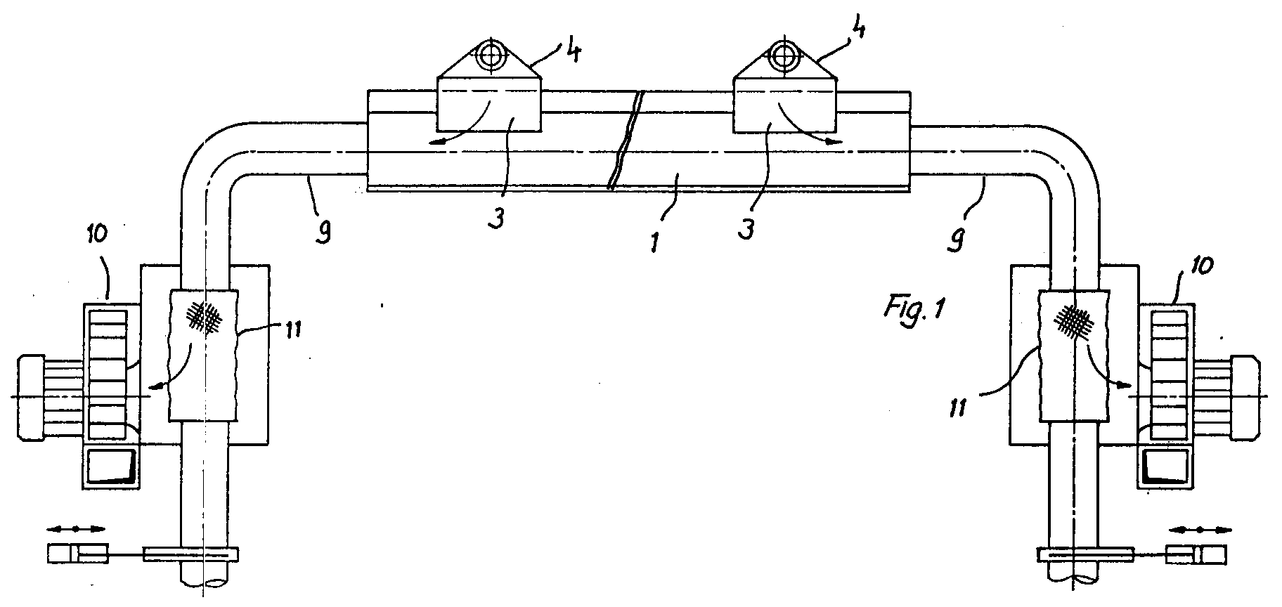
Description
Die Neuerung betrifft eine Reinigungsanlage für Textilmaschinen nach dem Oberbegriff des Anspruches 1.The innovation relates to a cleaning system for textile machines according to the preamble of claim 1.
Bei den bekannten Reinigungsanlagen dieser Art ist ein Ende des Saugkanals an die Saugseite eines Gebläses angeschlossen und längs des stationären Saugkanals ist ein Wanderreiniger verfahrbar. Dieser dient zum Reinigen mehrerer in einer Reihe angeordneter Textilmaschinen. Zu diesem Zweck weist der Wanderreiniger Saugschläuche auf, die bis in den Bodenbereich reichen und den dort abgesetzten Faserflug aufsaugen.In the known cleaning systems of this type, one end of the suction channel is connected to the suction side of a blower and a traveling cleaner can be moved along the stationary suction channel. This is used to clean several textile machines arranged in a row. For this purpose, the traveling cleaner has suction hoses that reach into the floor area and soak up the fiber fly deposited there.
Soll eine der Textilmaschinen vom Wanderreiniger nicht überfahren werden, beispielsweise wegen eines Maschinenstillstands, der eine Reparatur erforderlich macht, dann werden vom Wanderreiniger die davor liegenden Textilmaschinen nach wie vor gereinigt, nicht jedoch die Textilmaschinen, die hinter der nicht zu überfahrenden Maschine angeordnet sind. Die dahinter angeordneten Maschinen verschmutzen daher sehr rasch, was zu Ausschußware führt.If one of the textile machines is not to be run over by the traveling cleaner, for example because of a machine downtime that necessitates a repair, the traveling machine will continue to clean the textile machines in front of it, but not the textile machines that are arranged behind the machine that is not to be passed over. The machines arranged behind it get dirty very quickly, which leads to rejects.
Es besteht die Aufgabe, die Reinigungsanlage so auszubilden, daß eine Reinigung der vor und hinter einer nicht zu überfahrenden Textilmaschine angeordneten Textilmaschinen gewährleistet ist.The task is to design the cleaning system in such a way that cleaning of the textile machines arranged in front of and behind a textile machine which cannot be run over is ensured.
Gelöst wird diese Aufgabe mit den kennzeichnenden Merkmalen des Anspruches 1. Vorteilhafte Ausgestaltungen sind den Unteransprüchen entnehmbar.This object is achieved with the characterizing features of claim 1. Advantageous refinements can be found in the subclaims.
Ausführungsbeispiele werden nachfolgend anhand der Zeichnungen näher erläutert.
Es zeigen:
- Fig. 1
- eine schematische Ansicht eines ersten Ausführungsbeispiels der Reinigungsanlage;
- Fig. 2
- eine Draufsicht auf den Saugkanal mit den dort eingreifenden Saugrüsseln;
- Fig. 3
- eine der Figur 1 entsprechende Ansicht bei einem zweiten Ausführungsbeispiel;
- Fig. 4
- eine der
Figur 2 entsprechende Draufsicht des zweiten Ausführungsbeispiels; - Fig. 5
- einen Schnitt längs der Linie A - B in
Figur 3; - Fig. 6
- eine der Figur 1 entsprechende Ansicht bei einem dritten Ausführungsbeispiel;
- Fig. 7
- eine der
Figur 2 entsprechende Draufsicht beim dritten Ausführungsbeispiel; - Fig. 8
- eine Ansicht bei einem vierten Ausführungsbeispiel;
- Fig. 9
- eine der
Figur 2 entsprechende Draufsicht beim vierten Ausführungsbeispiel; - Fig. 10
- eine Draufsicht auf einen Teil eines gekrümmten Saugkanals;
- Fig. 11
- eine schematische Draufsicht auf eine Saugrüsselkonstruktion zum Befahren eines gekrümmten Saugkanals und
- Fig. 12
- eine schematische Draufsicht auf ein weiteres Ausführungsbeispiel einer Saugrüsselkonstruktion.
Show it:
- Fig. 1
- a schematic view of a first embodiment of the cleaning system;
- Fig. 2
- a plan view of the suction channel with the suction probes engaging there;
- Fig. 3
- a view corresponding to Figure 1 in a second embodiment;
- Fig. 4
- a plan view corresponding to Figure 2 of the second embodiment;
- Fig. 5
- a section along the line A - B in Figure 3;
- Fig. 6
- a view corresponding to Figure 1 in a third embodiment;
- Fig. 7
- a plan view corresponding to Figure 2 in the third embodiment;
- Fig. 8
- a view in a fourth embodiment;
- Fig. 9
- a plan view corresponding to Figure 2 in the fourth embodiment;
- Fig. 10
- a plan view of part of a curved suction channel;
- Fig. 11
- is a schematic plan view of a proboscis structure for driving on a curved suction channel and
- Fig. 12
- is a schematic plan view of another embodiment of a proboscis construction.
In den Zeichnungen ist der Saugkanal 1 schematisiert extrem kurz dargestellt, er weist üblicherweise die Länge einer Maschinenhalle auf. Der im Querschnitt rechteckige Saugkanal 1 ist oben mit einem längsverlaufenden Spalt versehen, der durch zwei elastische Dichtlippen 2 begrenzt ist. Zwischen diese Dichtlippen 2 greift jeweils ein schiffchenförmiger Saugrüssel 3 eines Wanderreinigers 4 ein. Es sind zwei getrennt verfahrbare Wanderreiniger 4 vorgesehen. Jeder Wanderreiniger 4 weist ein Fahrgestell 5 auf, welches längs Schienen 6 verfahrbar ist, die auf den Textilmaschinen montiert sind. Jeder Saugrüssel 3 steht in Verbindung mit einem Verteilerkasten 7, an den zwei Saugschläuche 8 angeschlossen sind, deren Mündung den Bodenbereich beidseits der Textilmaschine bestreichen. An jedes Ende des Saugkanals 1 sind über Rohrleitungen 9 Gebläse 10 mit ihrer Saugseite angeschlossen, wobei zwischen den Rohrleitungen 9 und den Gebläsen 10 jeweils ein Filtersieb 11 angeordnet ist. Im Betrieb wird Luft über die Mündungen der Saugschläuche 8 angesaugt, wobei die angesaugte Luft über den jeweiligen Verteilerkasten 7, den Saugrüssel 3, den Saugkanal 1, die Rohrleitungen 9 zu den Ventilatoren 10 gelangt und hierbei der mitgeführte Faserflug am jeweiligen Filtersieb 11 abgeschieden wird. Die Führung der Saugluft ist in den Figuren 1 und 5 durch die Pfeile verdeutlicht.In the drawings, the suction duct 1 is shown extremely briefly in schematic form, it usually has the length of a machine hall. The suction channel 1, which is rectangular in cross section, is provided at the top with a longitudinal gap which is delimited by two
Wie bereits erwähnt, sind die beiden Wanderreiniger 4 getrennt voneinander verfahrbar. Soll eine Textilmaschine von den Wanderreinigern 4 nicht überfahren werden, dann wird von den Wanderreinigern 4 diese Textilmaschine ausgespart, jedoch die vor und hinter dieser Textilmaschine angeordneten Textilmaschinen von jeweils einem der Wanderreiniger 4 überfahren. Somit ist gewährleistet, daß alle arbeitenden Textilmaschinen gereinigt werden.As already mentioned, the two traveling
Bei dem Ausführungsbeispiel nach Figur 1 sind an jedem Ende des Saugkanals ein Gebläse 10 angeschlossen. Zwei Wanderreiniger 4 greifen mit ihrem Saugrüssel in den Saugkanal 1 ein.In the exemplary embodiment according to FIG. 1, a
Um die Unterdruckverhältnisse für die Wanderreiniger 4 unabhängig voneinander zu halten, ist gemäß den Figuren 3 und 4 im Innern des Saugkanals 1 eine Trennwand 12 vorgesehen, welche abdichtend gegen die Innenwände des Saugkanals 1 anliegt. Diese Trennwand 12 ist Teil eines Doppel-T-Gestells 13, das an seiner Unterseite beidseits der Trennwand 12 Rollen 14 aufweist, die sich auf dem Boden des Saugkanals 1 abstützen. Das Gestell 13 ist im Innern des Saugkanals 1 verschiebbar, wenn einer der Wanderreiniger 4 gegen das Gestell 13 anläuft. Es entstehen auf diese Weise eine linke und eine rechte Kanalhälfte, welche jeweils an einen der Ventilatoren 10 angeschlossen sind.In order to keep the vacuum conditions for the traveling
Bei dem Ausführungsbeispiel nach den Figuren 6 und 7 ist jeder Wanderreiniger 4 mit einer Trennwand 12A versehen, welche abdichtend gegen die Innenwände des Saugkanals 1 anliegt. Die Trennwände 12A sind an den einander zugewandten Seiten der Wanderreiniger 4 angeordnet und werden mit diesen mitgeführt. Es entstehen auf diese Weise drei Kanalabschnitte, wobei der linke und der rechte Kanalabschnitt an das linke bzw. rechte Gebläse angeschlossen sind, während der Kanalabschnitt zwischen den Trennwänden 12A drucklos ist.In the embodiment according to FIGS. 6 and 7, each traveling cleaner 4 is provided with a
Bei dem Ausführungsbeispiel nach den Figuren 8 und 9 liegt eine Kombination des zweiten und dritten Ausführungsbeispiels vor. Hierbei weist jeder Wanderreiniger 4 eine Trennwand 12A auf, während zwischen den Trennwänden 12A die anhand der Figuren 3 und 4 beschriebene, verschiebbare Trennwand 12 angeordnet ist. Dieses Ausführungsbeispiel eignet sich insbesondere für den Fall, daß eine gute Abdichtung zwischen den Innenwänden des Saugkanals 1 und den Trennwänden 12A nicht gewährleistet ist.In the exemplary embodiment according to FIGS. 8 and 9, there is a combination of the second and third exemplary embodiments. Each traveling cleaner 4 has a
Vielfach reinigen die Wanderreiniger 4 mehrere parallel zueinander angeordnete Textilmaschinenreihen. Hierbei ist es bekannt, vor jede Textilmaschinenreihe einen Saugkanal 1 vorzusehen. Am Ende einer Maschinenreihe klinkt sich der Wanderreiniger aus dem dortigen Saugkanal aus, wird über Schienen 6 zur nächsten Maschinenreihe verfahren und klinkt sich dort in den dortigen Saugkanal ein.In many cases, the traveling
Um dieses Aus- und Einklinken zu vermeiden, verläuft gemäß Figur 10 der Saugkanal 1 bogenförmig von einer Maschinenreihe zur nächsten Maschinenreihe. In gleicher Weise gilt dies für die Schienen 6. Damit die Wanderreiniger die Bögen des Saugkanals 1 durchfahren können, münden im Verteilerkasten zwei schiffchenförmige Saugrüssel 3A, die in Fahrtrichtung gesehen hintereinander angeordnet sind und von denen jeder drehbar am Verteilerkasten 7 gelagert ist. Wie in Figur 11 gestrichelt dargestellt, passen sich diese Saugrüssel 3A der Bogenform an.In order to avoid this disengagement and engagement, the suction channel 1 runs in an arc from one machine row to the next machine row according to FIG. In the same way, this applies to the
Gemäß Figur 12 ist der Saugrüssel 3B quer zur Fahrtrichtung zweigeteilt, wobei die beiden Teile gelenkig miteinander verbunden sind. Auch hier ist eine Anpassung an die Bogenform möglich, wie gestrichelt dargestellt. Da der Bereich zwischen zwei benachbarten Textilmaschinenreihen nicht unbedingt gründlich gereinigt werden muß, kann es bei den Bogenfahrten in Kauf genommen werden, daß die Dichtlippen 2 nicht völlig abdichtend gegen die Saugrüssel 3A, 3B anliegen.According to FIG. 12, the
Claims (10)
Applications Claiming Priority (2)
| Application Number | Priority Date | Filing Date | Title |
|---|---|---|---|
| DE9205280U | 1992-04-16 | ||
| DE9205280U DE9205280U1 (en) | 1992-04-16 | 1992-04-16 | Cleaning system for textile machines |
Publications (3)
| Publication Number | Publication Date |
|---|---|
| EP0565780A2 true EP0565780A2 (en) | 1993-10-20 |
| EP0565780A3 EP0565780A3 (en) | 1993-11-18 |
| EP0565780B1 EP0565780B1 (en) | 1996-06-12 |
Family
ID=6878600
Family Applications (1)
| Application Number | Title | Priority Date | Filing Date |
|---|---|---|---|
| EP92121982A Expired - Lifetime EP0565780B1 (en) | 1992-04-16 | 1992-12-24 | Cleaning device for textile machines |
Country Status (4)
| Country | Link |
|---|---|
| US (1) | US5379482A (en) |
| EP (1) | EP0565780B1 (en) |
| DE (2) | DE9205280U1 (en) |
| ES (1) | ES2090471T3 (en) |
Cited By (2)
| Publication number | Priority date | Publication date | Assignee | Title |
|---|---|---|---|---|
| DE19526837A1 (en) * | 1995-07-22 | 1997-01-23 | Rieter Ingolstadt Spinnerei | Underpressure link for textile machine maintenance |
| CN111778600A (en) * | 2020-07-03 | 2020-10-16 | 广东国优机械科技有限公司 | Weaving is with weaving quick-witted weaving dirt collecting device |
Families Citing this family (5)
| Publication number | Priority date | Publication date | Assignee | Title |
|---|---|---|---|---|
| DE19831007C1 (en) * | 1998-07-10 | 1999-10-28 | Neuenhauser Maschbau Gmbh | Traveling cleaner for textile machines connected with seals to suction duct and having reduced overall height |
| CN103757769A (en) * | 2013-12-23 | 2014-04-30 | 苏州纺友新材料有限公司 | Textile device convenient to clean |
| CN108465682B (en) * | 2018-04-20 | 2023-11-24 | 四川亚缇纺织科技有限公司 | A waste cleaning device for textile workshops |
| CN116876122A (en) * | 2023-07-31 | 2023-10-13 | 宜城市万众纱业有限责任公司 | Rail type cleaning dust collection device of roving frame |
| CN118668342B (en) * | 2024-08-21 | 2024-12-13 | 浙江创维纺织有限公司 | Textile machine textile dust collecting equipment for spinning |
Family Cites Families (9)
| Publication number | Priority date | Publication date | Assignee | Title |
|---|---|---|---|---|
| US2585776A (en) * | 1949-05-26 | 1952-02-12 | Ceskoslovenske Textilni Zd Y | Method and device for removing impurities by aspiration from rollers of carding machines |
| US2634560A (en) * | 1950-09-27 | 1953-04-14 | Johns Manville | Traveling waste collector |
| US3018503A (en) * | 1956-12-27 | 1962-01-30 | Nippon Spindle Mfg Co Ltd | Frame cleaning device utilizing exhaust air from a suction cleaner in spinning and like operations |
| US3003177A (en) * | 1958-07-15 | 1961-10-10 | Nippon Spindle Mfg Co Ltd | Nozzle construction for textile machinery cleaning apparatus |
| GB1077718A (en) * | 1963-05-29 | 1967-08-02 | Leesona Holt Ltd | Improvements in suction cleaning equipment for winding machines |
| DE1560308A1 (en) * | 1966-05-23 | 1971-01-21 | Stemmann Ohg A | Method and device for sucking off and / or blowing off fluff, dust, etc. on textile machines or the like. |
| US3697691A (en) * | 1968-07-23 | 1972-10-10 | Graphic Sciences Inc | Electro-sensitive printing resin control system |
| US3534658A (en) * | 1969-03-03 | 1970-10-20 | Kirk & Blum Mfg Co | Chip entraining and removal apparatus for metal cutting machines |
| FR2396107A1 (en) * | 1977-07-01 | 1979-01-26 | Alsacienne Constr Meca | Automatic cleaning and piecing-up carriages - for yarn spinning machines with both functions performed from a single carriage |
-
1992
- 1992-04-16 DE DE9205280U patent/DE9205280U1/en not_active Expired - Lifetime
- 1992-12-24 DE DE59206571T patent/DE59206571D1/en not_active Expired - Fee Related
- 1992-12-24 EP EP92121982A patent/EP0565780B1/en not_active Expired - Lifetime
- 1992-12-24 ES ES92121982T patent/ES2090471T3/en not_active Expired - Lifetime
-
1993
- 1993-04-16 US US08/046,820 patent/US5379482A/en not_active Expired - Fee Related
Cited By (4)
| Publication number | Priority date | Publication date | Assignee | Title |
|---|---|---|---|---|
| DE19526837A1 (en) * | 1995-07-22 | 1997-01-23 | Rieter Ingolstadt Spinnerei | Underpressure link for textile machine maintenance |
| US5749213A (en) * | 1995-07-22 | 1998-05-12 | Rieter Ingolstadt Spinnereimaschinenbau Ag | Process and device to connect a negative-pressure channel to a negative-pressure line in textile machines |
| DE19526837B4 (en) * | 1995-07-22 | 2007-01-04 | Rieter Ingolstadt Spinnereimaschinenbau Ag | Method for connecting a vacuum channel with a vacuum line and textile machine |
| CN111778600A (en) * | 2020-07-03 | 2020-10-16 | 广东国优机械科技有限公司 | Weaving is with weaving quick-witted weaving dirt collecting device |
Also Published As
| Publication number | Publication date |
|---|---|
| EP0565780A3 (en) | 1993-11-18 |
| US5379482A (en) | 1995-01-10 |
| DE9205280U1 (en) | 1992-06-17 |
| DE59206571D1 (en) | 1996-07-18 |
| ES2090471T3 (en) | 1996-10-16 |
| EP0565780B1 (en) | 1996-06-12 |
Similar Documents
| Publication | Publication Date | Title |
|---|---|---|
| CH670575A5 (en) | ||
| EP3730022B1 (en) | Filter element | |
| EP0565780B1 (en) | Cleaning device for textile machines | |
| DE2911322A1 (en) | DEVICE FOR DEBURRING AND CLEANING AREA WORKPIECES | |
| DE1786108C3 (en) | Device for the continuous dedusting of material webs | |
| DE102017113200B4 (en) | Furniture board edge cleaning device | |
| EP0535501A2 (en) | Dust removal plant for machines | |
| DE2223265A1 (en) | CLEANING DEVICE FOR INSULATING SURFACES | |
| DE3715217A1 (en) | DEVICE FOR EXTRACTION AND FILTERING DUST- AND / OR FIBER-AIR-BASED AIR ON SPINNING MACHINES | |
| EP0563081B1 (en) | Process for cleaning a drop separator and drop separator with cleaning device | |
| DE3716585C2 (en) | Device for separating various substances from a mixture, in particular for separating waste | |
| DE4105867C2 (en) | Filter device for liquid plastic pressure lines | |
| EP0391091B1 (en) | Vacuum belt filtration apparatus | |
| DE3602926A1 (en) | Suction nozzle | |
| DE2910186C3 (en) | Surface filter device | |
| DE2733421C3 (en) | Suction device for cards to keep the revolving flats clean | |
| DE7833705U1 (en) | SLIDING PLATE FOR VACUUM NOZZLE | |
| EP0835837A2 (en) | Method of and device for avoiding production failures in folding devices | |
| DE2601016C2 (en) | Method and device for cleaning filter boxes | |
| DE2832742A1 (en) | Cleaning long rows of textile machinery - using multiple blowing units mounted on overhead travelling bridge | |
| EP2534990A2 (en) | Floor nozzle for a vacuum cleaner and vacuum cleaner with such a floor nozzle | |
| DE102009008158A1 (en) | Device for cleaning workpieces | |
| CH434052A (en) | Device for the pneumatic cleaning of at least approximately horizontal surface strips on or under textile machines | |
| DE9016421U1 (en) | Overhead conveyor system | |
| EP0678335A2 (en) | Powder coating booth |
Legal Events
| Date | Code | Title | Description |
|---|---|---|---|
| PUAI | Public reference made under article 153(3) epc to a published international application that has entered the european phase |
Free format text: ORIGINAL CODE: 0009012 |
|
| PUAL | Search report despatched |
Free format text: ORIGINAL CODE: 0009013 |
|
| AK | Designated contracting states |
Kind code of ref document: A2 Designated state(s): CH DE ES FR GB GR IT LI NL |
|
| AK | Designated contracting states |
Kind code of ref document: A3 Designated state(s): CH DE ES FR GB GR IT LI NL |
|
| 17P | Request for examination filed |
Effective date: 19931111 |
|
| 17Q | First examination report despatched |
Effective date: 19950518 |
|
| GRAA | (expected) grant |
Free format text: ORIGINAL CODE: 0009210 |
|
| AK | Designated contracting states |
Kind code of ref document: B1 Designated state(s): CH DE ES FR GB GR IT LI NL |
|
| PG25 | Lapsed in a contracting state [announced via postgrant information from national office to epo] |
Ref country code: NL Free format text: LAPSE BECAUSE OF FAILURE TO SUBMIT A TRANSLATION OF THE DESCRIPTION OR TO PAY THE FEE WITHIN THE PRESCRIBED TIME-LIMIT Effective date: 19960612 Ref country code: GR Free format text: LAPSE BECAUSE OF FAILURE TO SUBMIT A TRANSLATION OF THE DESCRIPTION OR TO PAY THE FEE WITHIN THE PRESCRIBED TIME-LIMIT Effective date: 19960612 Ref country code: GB Effective date: 19960612 Ref country code: FR Effective date: 19960612 |
|
| REG | Reference to a national code |
Ref country code: CH Ref legal event code: NV Representative=s name: PATENTANWALTSBUREAU BOSSHARD UND LUCHS |
|
| REF | Corresponds to: |
Ref document number: 59206571 Country of ref document: DE Date of ref document: 19960718 |
|
| ITF | It: translation for a ep patent filed | ||
| REG | Reference to a national code |
Ref country code: ES Ref legal event code: FG2A Ref document number: 2090471 Country of ref document: ES Kind code of ref document: T3 |
|
| NLV1 | Nl: lapsed or annulled due to failure to fulfill the requirements of art. 29p and 29m of the patents act | ||
| EN | Fr: translation not filed | ||
| REG | Reference to a national code |
Ref country code: ES Ref legal event code: FG2A Ref document number: 2090471 Country of ref document: ES Kind code of ref document: T3 |
|
| GBV | Gb: ep patent (uk) treated as always having been void in accordance with gb section 77(7)/1977 [no translation filed] |
Effective date: 19960612 |
|
| PG25 | Lapsed in a contracting state [announced via postgrant information from national office to epo] |
Ref country code: LI Effective date: 19961231 Ref country code: CH Effective date: 19961231 |
|
| PLBE | No opposition filed within time limit |
Free format text: ORIGINAL CODE: 0009261 |
|
| STAA | Information on the status of an ep patent application or granted ep patent |
Free format text: STATUS: NO OPPOSITION FILED WITHIN TIME LIMIT |
|
| 26N | No opposition filed | ||
| REG | Reference to a national code |
Ref country code: CH Ref legal event code: PL |
|
| PG25 | Lapsed in a contracting state [announced via postgrant information from national office to epo] |
Ref country code: DE Effective date: 19970902 |
|
| PG25 | Lapsed in a contracting state [announced via postgrant information from national office to epo] |
Ref country code: ES Free format text: LAPSE BECAUSE OF NON-PAYMENT OF DUE FEES Effective date: 19971225 |
|
| REG | Reference to a national code |
Ref country code: ES Ref legal event code: FD2A Effective date: 19980113 |
|
| PG25 | Lapsed in a contracting state [announced via postgrant information from national office to epo] |
Ref country code: IT Free format text: LAPSE BECAUSE OF NON-PAYMENT OF DUE FEES;WARNING: LAPSES OF ITALIAN PATENTS WITH EFFECTIVE DATE BEFORE 2007 MAY HAVE OCCURRED AT ANY TIME BEFORE 2007. THE CORRECT EFFECTIVE DATE MAY BE DIFFERENT FROM THE ONE RECORDED. Effective date: 20051224 |