EP0565940A1 - Douille avec lamelles inserée dans les cylindres du bloc moteur lors de la coulée - Google Patents
Douille avec lamelles inserée dans les cylindres du bloc moteur lors de la coulée Download PDFInfo
- Publication number
- EP0565940A1 EP0565940A1 EP93105221A EP93105221A EP0565940A1 EP 0565940 A1 EP0565940 A1 EP 0565940A1 EP 93105221 A EP93105221 A EP 93105221A EP 93105221 A EP93105221 A EP 93105221A EP 0565940 A1 EP0565940 A1 EP 0565940A1
- Authority
- EP
- European Patent Office
- Prior art keywords
- sleeve
- lamellae
- edge
- metal strip
- sheet metal
- Prior art date
- Legal status (The legal status is an assumption and is not a legal conclusion. Google has not performed a legal analysis and makes no representation as to the accuracy of the status listed.)
- Withdrawn
Links
Images


Classifications
-
- B—PERFORMING OPERATIONS; TRANSPORTING
- B22—CASTING; POWDER METALLURGY
- B22D—CASTING OF METALS; CASTING OF OTHER SUBSTANCES BY THE SAME PROCESSES OR DEVICES
- B22D19/00—Casting in, on, or around objects which form part of the product
- B22D19/0009—Cylinders, pistons
-
- F—MECHANICAL ENGINEERING; LIGHTING; HEATING; WEAPONS; BLASTING
- F02—COMBUSTION ENGINES; HOT-GAS OR COMBUSTION-PRODUCT ENGINE PLANTS
- F02F—CYLINDERS, PISTONS OR CASINGS, FOR COMBUSTION ENGINES; ARRANGEMENTS OF SEALINGS IN COMBUSTION ENGINES
- F02F1/00—Cylinders; Cylinder heads
- F02F1/02—Cylinders; Cylinder heads having cooling means
- F02F1/10—Cylinders; Cylinder heads having cooling means for liquid cooling
- F02F1/16—Cylinder liners of wet type
-
- F—MECHANICAL ENGINEERING; LIGHTING; HEATING; WEAPONS; BLASTING
- F16—ENGINEERING ELEMENTS AND UNITS; GENERAL MEASURES FOR PRODUCING AND MAINTAINING EFFECTIVE FUNCTIONING OF MACHINES OR INSTALLATIONS; THERMAL INSULATION IN GENERAL
- F16J—PISTONS; CYLINDERS; SEALINGS
- F16J10/00—Engine or like cylinders; Features of hollow, e.g. cylindrical, bodies in general
- F16J10/02—Cylinders designed to receive moving pistons or plungers
- F16J10/04—Running faces; Liners
-
- F—MECHANICAL ENGINEERING; LIGHTING; HEATING; WEAPONS; BLASTING
- F02—COMBUSTION ENGINES; HOT-GAS OR COMBUSTION-PRODUCT ENGINE PLANTS
- F02F—CYLINDERS, PISTONS OR CASINGS, FOR COMBUSTION ENGINES; ARRANGEMENTS OF SEALINGS IN COMBUSTION ENGINES
- F02F1/00—Cylinders; Cylinder heads
- F02F1/02—Cylinders; Cylinder heads having cooling means
- F02F1/10—Cylinders; Cylinder heads having cooling means for liquid cooling
- F02F2001/104—Cylinders; Cylinder heads having cooling means for liquid cooling using an open deck, i.e. the water jacket is open at the block top face
Definitions
- the invention relates to a sleeve to be poured into a cylinder block according to the preamble of patent claim 1.
- Such a sleeve is known from DE 39 41 381 A1.
- This sleeve is poured into a cylinder block made of light metal in such a way that when the cylinder barrel is subsequently unscrewed, the base surface connecting the fins, including the webs, is removed and only the separated lamella edges lie in the career.
- the invention has for its object to improve a sleeve to be poured into a cylinder block so that the Manufacture, transport and handling as well as further processing of the sleeve are made easier and more damage-proof and a tight fit of the fins in the finished cylinder block can be guaranteed.
- the selected arrangement and lateral undercut of the lamellae ensure that the lamellae turned off from the base surface fit well in the cylinder block and in particular open up the possibility of allowing a continuous edge strip of the base surface at the axial ends of the sleeve, which can be as narrow as desired and together is turned with the base and the webs between the lamellar strips during the machining of the cylinder raceway, but during the manufacture of the sleeve, i.e.
- the shape for the cylinder block casting ensures a comfortable and precise handling of the sleeve or the sheet metal strip forming the sleeve without risk of damage or bending of the fins.
- the edge strips can already be used as a handle for holding the sheet metal strip when cutting or cutting, punching, putting through the slats, transporting, bending and connecting the sheet metal strip ends and also for thermal coating and holding the sleeve in the injection mold for the cylinder block. Damage, bending, cutting or twisting of lamellas or lamellar parts does not occur during these activities or when the cylinder barrel is subsequently unscrewed.
- gusset-free gussets of the base near the axial ends of the sleeve can be provided with openings, which likewise do not impair the lamellae and thus the finished cylinder block.
- the edge strips can also be used according to claim 3 to form spacers at a sleeve end, which on the one hand facilitate the correct insertion of the sleeve into a flame spraying device or thermal coating device and into the injection mold for the cylinder block, and on the other hand for precise fixing of the sleeve in the Better shapes serve slightly conical cylinder molds.
- the molding of known spacers for this purpose is considerably simplified and not associated with impairment of the slats.
- the fixing of the end edges of the sheet metal strip in the form of a sleeve is carried out according to claims 4 to 6 by at least partially cutting the sheet metal strip to length along one or more webs, the projections on one end edge preferably serving as connecting devices, which are welded, latched or in some other way to the other end edge be firmly connected.
- the end edges can either run exclusively along a web or at the ends of a web also partially across the adjacent gusset. However, they can also run in a V-shape or a zigzag shape alternately along web sections and along punched-out slat edges. In any case, a simple connection of the end edges can be achieved through this design.
- punch punches are preferably used according to claim 7, which punch out a part of the slat and optionally the adjacent web. This results in side undercuts when pouring into the cylinder block, which anchors the lamellae in the cylinder block after the cylinder barrel has been unscrewed and the base, webs and edge strips removed.
- free gussets are provided at the axial ends of the sleeve of lamellae. Now, however, is at the dead centers, i.e. the reversal points of the piston in the cylinder of internal combustion engines, especially at top dead center, the stress on the cylinder surface is particularly high. It would therefore be desirable to provide lamellas in these gussets, but this does not appear to be possible with the sleeve according to the invention.
- the generation of the shortened lamellae by means of punches is particularly expedient.
- the helical arrangement of the lamellar tracks according to the invention results in band-shaped areas in the axial direction of the sleeve cast into a cylinder, which corresponds to the direction of movement of the piston in the cylinder, between the lamellar edges of adjacent lamellar tracks, in which the cylinder running surface is not reinforced by lamellar edges becomes.
- the still flat metal strip i.e. the metal plate used for the manufacture of the lamellar sleeve according to the invention
- the metal plate used for the manufacture of the lamellar sleeve according to the invention shows that the leading side edge of each lamellar which has been put through is always more inward is folded towards the base as the trailing side edge of the same slat.
- the lamellae in the finished sleeve have an internal twist, the penetration angle at the leading side edge being somewhat less than at the trailing side edge. This could affect the even anchoring of the slats in the light metal into which the sleeve is cast.
- the lamellae are therefore already given a twist when it is put through from the base surface, which counteracts the twist which is inevitably produced by the bending.
- this counteraction is just so great that the slats have an approximately constant pitch angle after bending the base to the sleeve. This ensures an excellent, constant anchoring of the slats in the light metal.
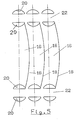
- a continuous sheet metal strip 10 is provided with parallel tracks 14 of slats 16 extending obliquely to its longitudinal extent 12, according to FIG. 1, by slightly curved lines 18 according to FIG. 5 to form the later inside the free lamella edges to be cast from cylinder block material and concave indentations 20 are formed at both ends of the curved lines 18 by perforated punches in the form of segments of a circle on the lateral edges of the lamellae 16. Between the individual lamella webs 14, webs 22 running through from the base area of the metal strip 10 remain unchanged.
- sleeve 30 At both axial ends of the sleeve, generally designated 30, or at the lateral edges of the metal strip 10 is provided in each case one with the width 36 through the entire circumference of the sleeve and free of lamella 16 edge strips 32 and 34 respectively.
- approximately triangular gussets 38 free of lamellae 16, of the unchanged base surface of the sheet metal strip 10 are formed, which are each connected to the edge strips 32, 34 and the webs 22 and in the same radial plane of the sleeve 30 lie.
- a circular hole 40 is provided in each of these gussets 38 for more convenient handling and transport of the sheet metal strip 10 and the sleeve 30 formed therefrom.
- the slats 16 are put through obliquely in the manner shown in FIG. 2, so that they protrude from the base of the sleeve 30 to the outside.
- the lamella tracks 14 arranged obliquely to the longitudinal extent 12 of the sheet metal strip 10 run helically on the sleeve according to FIG. 2.
- the beginning of a second sheet metal strip 10 a which is the same as the sheet metal strip 10 is shown in FIG. 1 in order to demonstrate the joining of the end edges 24 and 26 with the overlapping projections 28.
- the end edges 24 and 26 have at their respective ends an edge section 42 and 44 which runs perpendicular to the respective edge strips 32 and 34 and transversely penetrates the adjacent gusset 38 and which each carry a projection 28 .
- One edge strip 34 is provided in the region of each gusset 38 with a pair of approximately triangular incisions 46, which enclose between them a tab-shaped spacer 48 which is bent inwards in relation to the finished sleeve 30 in the manner shown in FIG. 2.
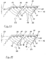
- the free lamella edges 18 ' are not produced by punching lines, but rather by punching out a strip which is slightly angled in the middle with otherwise straight-line boundaries and which is sharply angled at both ends to form the lateral indentations 20'.
- the end edges 24 'and 26' run alternately along a web 22 'and a free lamella edge 18' in a zigzag shape. The connection of the end edges 24 ', 26' after the formation of the sleeve 30 'shown in FIG.
- approximately triangular gussets of the base surface of the sheet metal strip 10 are formed between the edge strips 32 and the webs 22, which are each connected to the edge strips 32 and the webs 22 and lie in the same radial plane of the sleeve to be formed.
- the respective lamellar web 14 is provided in these gussets, but lamellas 17 are provided which are increasingly shortened in relation to the other lamellas 16 in their longitudinal extent towards the edge strips 32.
- these shortened lamellas 17 carry the same lateral indentations 20 as the non-shortened lamellas 16.
- punctiform or triangular and hatched in Figures 10 and 11 are preferably reproduced by punches Recesses 19 punched into the base of the metal strip 10.
- the embodiment according to FIG. 11 differs from FIG. 10 in that punched-in recesses 21 penetrate the edge strip 32 and are open to the outside, which simplifies the punching process.
- the connection of the entire sheet metal strip 10 guaranteed by the edge strip 32 is nevertheless ensured by the areas of the sheet metal strip 10 which remain stationary.
- the shortened fins 17 thus extend in a continuation of the not shortened fins 16 to the edge strip 32, so that the running surface of the cylinder to be manufactured is reinforced evenly by edges of cast-in fins, particularly in the particularly heavily used region 23, which corresponds to the reversing region of the piston is.
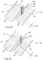
- the slats 16 are mutually aligned in the parallel slat tracks 14, so that one slat 16 of a slat track 14 with one slat 16 of the next slat track 14 lies within the same slat distance 25.
- the edge 27 of each lamella lying in this race after the finished sleeve has been molded, poured into the cylinder block and unscrewed from the cylinder race is indicated in FIGS. 12 and 13 by dashed lines.
- These lateral band-shaped regions 31a according to FIG. 12 have a substantially larger extension in the piston running direction, i.e. perpendicular to the longitudinal extent 12, as the corresponding band-shaped regions 33 according to FIG. 13. This is achieved when the slats 16 of one track 14 are offset against the slats 16 of the adjacent track 14 by half a slat depth 35.
- the length of the piston movement on a non-reinforced cylinder race can be effectively shortened by this measure.
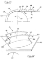
- the lamellae 16 are given a twist when passing through from the sheet metal strip 10, which corresponds to a twist angle 47 on the outer edge 18 (FIG. 15).
- the outer diameter of the leading edge 43 is therefore larger than the outer diameter of the trailing edge 45. This corresponds to a somewhat larger pitch angle at the leading edge 43 and a somewhat smaller pitch angle of the lamella 16 at the trailing edge 45.
- the subsequent bend then makes the outside diameter of the lamella 16 and at the same time the angle of penetration thereof approximately constant over the entire length of the free lamella edge 18. This results in an approximately uniform depth of embedding of the lamellas 16 when pouring into the cylinder block and thus a consistently good anchoring thereof.
Landscapes
- Engineering & Computer Science (AREA)
- Mechanical Engineering (AREA)
- General Engineering & Computer Science (AREA)
- Chemical & Material Sciences (AREA)
- Combustion & Propulsion (AREA)
- Cylinder Crankcases Of Internal Combustion Engines (AREA)
Applications Claiming Priority (4)
| Application Number | Priority Date | Filing Date | Title |
|---|---|---|---|
| DE4212355 | 1992-04-13 | ||
| DE19924212355 DE4212355C1 (en) | 1992-04-13 | 1992-04-13 | Cooling finned sleeve cast into IC engine light metal cylinder block - is made from sheet metal bent to cylindrical form and placed in mould for cylinder block casting |
| DE4225717 | 1992-08-04 | ||
| DE4225717 | 1992-08-04 |
Publications (1)
| Publication Number | Publication Date |
|---|---|
| EP0565940A1 true EP0565940A1 (fr) | 1993-10-20 |
Family
ID=25913924
Family Applications (1)
| Application Number | Title | Priority Date | Filing Date |
|---|---|---|---|
| EP93105221A Withdrawn EP0565940A1 (fr) | 1992-04-13 | 1993-03-30 | Douille avec lamelles inserée dans les cylindres du bloc moteur lors de la coulée |
Country Status (4)
| Country | Link |
|---|---|
| EP (1) | EP0565940A1 (fr) |
| CZ (1) | CZ61293A3 (fr) |
| DE (1) | DE4226743C2 (fr) |
| HU (1) | HUT65040A (fr) |
Families Citing this family (1)
| Publication number | Priority date | Publication date | Assignee | Title |
|---|---|---|---|---|
| GB0123854D0 (en) * | 2001-10-04 | 2001-11-28 | Ricardo Consulting Eng | Engines of reciprocating piston type |
Citations (3)
| Publication number | Priority date | Publication date | Assignee | Title |
|---|---|---|---|---|
| FR1310374A (fr) * | 1962-01-15 | 1962-11-23 | Mahle Kg | Cylindre en métal léger chemisé et son procédé de fabrication |
| EP0086357A1 (fr) * | 1982-02-12 | 1983-08-24 | FIAT Veicoli Industriali S.p.A. | Procédé pour la fabrication d'un bloc-cylindre pour moteurs à combustion interne à piston alternatif et bloc-cylindre fabriqué par ledit procédé |
| DE3941381A1 (de) * | 1989-12-15 | 1991-06-20 | Audi Ag | Zylinderblock fuer eine brennkraftmaschine |
-
1992
- 1992-08-13 DE DE4226743A patent/DE4226743C2/de not_active Expired - Fee Related
-
1993
- 1993-03-30 EP EP93105221A patent/EP0565940A1/fr not_active Withdrawn
- 1993-04-07 HU HU9301016A patent/HUT65040A/hu unknown
- 1993-04-09 CZ CZ93612A patent/CZ61293A3/cs unknown
Patent Citations (3)
| Publication number | Priority date | Publication date | Assignee | Title |
|---|---|---|---|---|
| FR1310374A (fr) * | 1962-01-15 | 1962-11-23 | Mahle Kg | Cylindre en métal léger chemisé et son procédé de fabrication |
| EP0086357A1 (fr) * | 1982-02-12 | 1983-08-24 | FIAT Veicoli Industriali S.p.A. | Procédé pour la fabrication d'un bloc-cylindre pour moteurs à combustion interne à piston alternatif et bloc-cylindre fabriqué par ledit procédé |
| DE3941381A1 (de) * | 1989-12-15 | 1991-06-20 | Audi Ag | Zylinderblock fuer eine brennkraftmaschine |
Also Published As
| Publication number | Publication date |
|---|---|
| DE4226743A1 (de) | 1994-02-10 |
| DE4226743C2 (de) | 1997-08-21 |
| CZ61293A3 (en) | 1994-02-16 |
| HU9301016D0 (en) | 1993-06-28 |
| HUT65040A (en) | 1994-03-28 |
Similar Documents
| Publication | Publication Date | Title |
|---|---|---|
| DE10155045C2 (de) | Komponente zu einem statischen Mischer | |
| DE2265310B2 (de) | Statorkern für rotierende elektrische Maschinen | |
| DE10037410A1 (de) | Rotierende elektrische Maschine und Verfahren zu deren Herstellung | |
| EP0499154A1 (fr) | Epurateur | |
| DE10014581C2 (de) | Stabilisierungsstrebe für ein Fahrwerk eines Fahrzeugs sowie Verfahren zur Herstellung derselben | |
| AT518889B1 (de) | Bewehrungselement | |
| DE3347503A1 (de) | Selbstsichernder sperrbolzen | |
| DE3615230C2 (fr) | ||
| DE2548853C3 (de) | Vorrichtung zur Herstellung von metallenen Ringrohlingen | |
| DE2516340A1 (de) | Flachschluessel fuer zylinderschloesser | |
| EP0565940A1 (fr) | Douille avec lamelles inserée dans les cylindres du bloc moteur lors de la coulée | |
| DE10014603C2 (de) | Stabilisierungsstrebe für ein Fahrwerk eines Fahrzeugs | |
| EP0531879B1 (fr) | Lame de scie à ruban et procédé pour sa fabrication | |
| DE10340114A1 (de) | Elektrische Maschine mit einem geblechten weichmagnetischen Körper und Verfahren zu ihrer Herstellung | |
| DE4317665C2 (de) | In den Zylinderblock einer Brennkraftmaschine einzugießende Lamellenhülse | |
| DE60221393T2 (de) | Verfahren zur Herstellung eines vertikalen Gerüstelementes, und durch Anwendung dieses Verfahrens hergestelltes Element | |
| DE4212355C1 (en) | Cooling finned sleeve cast into IC engine light metal cylinder block - is made from sheet metal bent to cylindrical form and placed in mould for cylinder block casting | |
| EP2019157B1 (fr) | Lisse coudée et étroite | |
| EP4433734B1 (fr) | Tuyau à paroi mince, matériau plat métallique, et procédé de production d'un tuyau à paroi mince | |
| EP3636851B1 (fr) | Profilé d'enduit | |
| EP0289658B1 (fr) | Bras d'essuie-glace, en particulier pour des dispositions d'essuie-glace des automobiles | |
| CH675614A5 (fr) | ||
| DE102010019458A1 (de) | Metallband als Einlage für Profilleisten und Verfahren zur Herstellung eines Metallbandes | |
| EP1222730A1 (fr) | Procede pour produire une bande | |
| DE29921972U1 (de) | Anschlußende eines Metallschlauches und Vorrichtung zu dessen Herstellung |
Legal Events
| Date | Code | Title | Description |
|---|---|---|---|
| PUAI | Public reference made under article 153(3) epc to a published international application that has entered the european phase |
Free format text: ORIGINAL CODE: 0009012 |
|
| AK | Designated contracting states |
Kind code of ref document: A1 Designated state(s): DE ES FR GB IT |
|
| 17P | Request for examination filed |
Effective date: 19931202 |
|
| 17Q | First examination report despatched |
Effective date: 19950125 |
|
| 18D | Application deemed to be withdrawn |
Effective date: 19950902 |