EP0565992A2 - Procédé et système pour surveiller le trafic et informer les usagers de la voie publique - Google Patents
Procédé et système pour surveiller le trafic et informer les usagers de la voie publique Download PDFInfo
- Publication number
- EP0565992A2 EP0565992A2 EP93105650A EP93105650A EP0565992A2 EP 0565992 A2 EP0565992 A2 EP 0565992A2 EP 93105650 A EP93105650 A EP 93105650A EP 93105650 A EP93105650 A EP 93105650A EP 0565992 A2 EP0565992 A2 EP 0565992A2
- Authority
- EP
- European Patent Office
- Prior art keywords
- traffic
- road
- processor
- sensors
- signal
- Prior art date
- Legal status (The legal status is an assumption and is not a legal conclusion. Google has not performed a legal analysis and makes no representation as to the accuracy of the status listed.)
- Granted
Links
Images



Classifications
-
- G—PHYSICS
- G08—SIGNALLING
- G08G—TRAFFIC CONTROL SYSTEMS
- G08G1/00—Traffic control systems for road vehicles
- G08G1/01—Detecting movement of traffic to be counted or controlled
- G08G1/042—Detecting movement of traffic to be counted or controlled using inductive or magnetic detectors
-
- G—PHYSICS
- G08—SIGNALLING
- G08G—TRAFFIC CONTROL SYSTEMS
- G08G1/00—Traffic control systems for road vehicles
- G08G1/01—Detecting movement of traffic to be counted or controlled
- G08G1/052—Detecting movement of traffic to be counted or controlled with provision for determining speed or overspeed
-
- G—PHYSICS
- G08—SIGNALLING
- G08G—TRAFFIC CONTROL SYSTEMS
- G08G1/00—Traffic control systems for road vehicles
- G08G1/07—Controlling traffic signals
-
- G—PHYSICS
- G08—SIGNALLING
- G08G—TRAFFIC CONTROL SYSTEMS
- G08G1/00—Traffic control systems for road vehicles
- G08G1/09—Arrangements for giving variable traffic instructions
- G08G1/095—Traffic lights
Definitions
- the invention relates to a method for monitoring road traffic and for early information and warning of road users in the event of traffic disruptions, their own misconduct, dangerous road conditions and / or critical weather conditions, and also to a traffic monitoring and information system used to carry out the method.
- variable message signs can only be found at certain points at critical junctions. It is also unsatisfactory and, above all, that the periods from the respective traffic detection to the traffic influencing are too long in relation to the highly dynamic traffic events to warn the traffic in good time of identified critical traffic situations or even to reduce the risk of subsequent accidents if an accident is detected.
- a traffic monitoring and information system is also known with radio beacons arranged at a distance from one another along a street with lights which are connected to a control room and are controlled via integrated receiving systems.
- the receiving systems of the signal lights communicate with transmitters arranged in motor vehicles, which in turn are controlled by speed and crash sensors also installed in the vehicles and are used to control the lights in the radio beacons.
- This traffic monitoring and information system is about a light chain system communicating with sensors installed in vehicles via suitable receiving and transmitting systems and thereby being able to send out corresponding warning signals when traffic-related driving conditions or even when individual vehicles or groups of vehicles are at a standstill .
- the prerequisite for the fact that the driving conditions of a motor vehicle participating in traffic can be recorded and used to control the beacon system must be equipped with this vehicle corresponding sensors and a transmission system which can be controlled by the latter.
- the driving conditions of all other motor vehicles participating in traffic cannot be detected and therefore cannot trigger information or warning signals.
- the invention has for its object to provide a method of the type and intended use that dynamic monitoring of all road traffic in a section equipped with such a monitoring and information system and the early information and warning of road users and thus influencing the Enables traffic, but for which it is not necessary to equip the vehicles with the appropriate sensors and transmitters.
- a traffic monitoring and information system for carrying out such a method is also to be created.
- the object of the invention is achieved in that traffic and / or road conditions ascertained or entered by means of roadside traffic and load detection devices are displayed by means of illuminated elements with signal lights, arranged at intervals from one another along the road guidance, connected to light chains and controllable together or sequentially continuous traffic information and possibly warning in real time.
- the invention therefore relates to the fact that, depending on traffic and / or road conditions which have been determined or also entered by the traffic and load detection devices, the road users information about these conditions and / or faults which have a direct effect on the behavior of the road users are brought to the attention by means of signal lights which are spaced apart from one another along the route of the road.
- the light chains made of interconnected light elements can be operated continuously with a given light chain length as road guidance aids. This can be done, for example, with light pulses running forwards and backwards in two directions along the respective light chain, it being possible for pulse lengths, frequency and switch-on ratio to be variable.
- the signal lights of the lighting elements can be operated in the blinking mode in the event of measured violations, such as excessive speed, truck overtaking ban, overloading of axles, wrong direction of travel or the like, and thus information for detected traffic violations can be given to the respective road user.
- the light chains are expediently operated in real time in interaction with the traffic and / or load detection devices when using different fault detection algorithms.
- the flashing modes of individual signal lights in front of a vehicle can also be visibly operated with the same running speed and the same route, and advantageously until the end of the detected violation. A road user is not only continuously informed about his misconduct, but also encouraged them to return to traffic-oriented driving.
- another embodiment of the method according to the invention provides that the sensitivity to the visual threshold and the above-threshold brightness classification of the signal lights is increased or optimized in comparison to the permanent lighting by means of an ergonomically optimized pulse frequency, that is, the subjective conspicuousness is increased.
- the lighting elements can also be operated with different brightness depending on the time of day or season (day / night, summer / winter).
- Another important process design enables effective traffic influencing by the fact that the signal lights of the light chains are connected to one another with light elements running in the direction of travel along the light chain at the directional speed with the result that the road users make an intuitive effort to keep their driving speed at the same as that in the direction of travel adapting the given directional speed to the current light pulses. This necessarily leads to an equalization and calming of the traffic due to synchronous driving of all road users.
- a still further process design provides that the signal lights of the light chains are operated with light impulses driving traffic and traveling in the direction of travel, in order not to do so to immediately resolve traffic-related congestion or viscous liquids in traffic, as can often occur, for example, in the event of an accident on the opposite lane or in spectacular but traffic-independent events. It can be expedient to operate the signal lamps of the lighting elements with differently colored light pulses. The lighting status of the lighting elements or lighting chains can also be monitored and controlled by a control room.
- a road sensor system with a connected evaluation and control unit controls and activates several light chain elements backwards against the direction of traffic in order to inform the following traffic about traffic and / or road conditions in the section of the road ahead to transfer.
- the method according to the invention can also be operated in such a way that to achieve real-time behavior and to cover continuous road sections, the light chains are operated either by activation by means of a road sensor element with evaluation electronics and automatic fault detection or manual activation, with the result of a shorter reaction time, by activation as a result of evaluating the traffic data from two or more sensors and evaluation units and comparative traffic data evaluation, which leads to an average response time, or by activation via evaluations of the sensors using methods in control rooms, which, however, requires a longer response time.
- a measuring point with traffic and / or load detection devices acting essentially transversely to the lane of a road Statically or dynamically coupled lighting elements with signal lights as optical signal transmitters and at least one road processor as evaluation and control unit for evaluating determined traffic and / or road conditions and for controlling and activating the signal lights are assigned in accordance with the road layout.
- the system according to the invention installs in the form of light chains along at least one side of the street Lighting elements are not controlled by radio from the vehicle's own sensors and transmitters or from a control room, but by means of roadside sensors via a road processor processing the traffic and / or road conditions detected by the latter, which then send out signals corresponding to the determined traffic situation.
- These can be individual pulses or group pulses in front of moving vehicles, but also synchronized light waves that are used to drive forward or backward at different frequencies to drive or slow down traffic.
- the system can, however, also have a plurality of measuring points along a road at predetermined distances from one another with traffic and / or load detection devices, coupled lighting elements and at least one road processor as evaluation and control unit, so that a monitoring and information system covering at least sections is available.
- the lighting elements can be arranged on the right or left side following the course of the road. However, the arrangement of the lighting elements on both sides of the street has proven particularly expedient proven.
- the lighting elements can be connected to one another as a light bus to form chains and can be controlled individually, in groups or together and can also be switched to at least two different signal colors, such as yellow and red.
- the lighting elements or signal lights are equipped with a manually operated emergency switch for switching on lighting chains, for example in order to activate lighting elements in the opposite direction to the flow of traffic for a distance which can be defined as a function of the road layout.
- the road processors of several measuring points which serve as evaluation and control units and which are arranged depending on the local conditions, for example at intervals of a few hundred meters, can expediently be connected to one another via a communication network.
- the traffic and / or load detection devices can expediently be speed sensors, axle detectors, induction loops, weighing plates, wheel load meters and similar devices.
- each measuring point is provided as an evaluation unit with a road processor for detecting and evaluating determined traffic and / or road conditions and as a control unit with a signal processor operatively connected to the traffic processor for controlling the lighting modules or lighting elements.
- the roadside sensor system of the measuring points for detecting the traffic and / or road conditions is connected via a network to a road processor which, as the main processor, controls the signal lights of the lighting elements individually, collectively or in a predetermined sequence and Interface cards for different sensors or signal processing units coordinated.
- the roadside sensors can be induction loops, axle detectors or weighing sensors installed in the road surface, such as weighing plates based on strain gauges, piezo sensors or capacitive strip sensors, but also sonar sensors, microwave sensors and / or, for example, infrared sensors that are not installed in the road surface will.
- measuring points can also be successively fitted along a street, each with sensors connected via a network to a street processor for detecting the traffic and / or street conditions, the street processors being connected to one another by means of a processor network.
- each road processor is operatively connected to the sensor system assigned to it, and the road processors assigned to different route sections communicate with one another.
- a system designed in this way is the basis for real-time control of traffic.
- Another embodiment of the invention sees one Structure of the road processor in such a way that the entire measuring cross-section of the lanes of a road and sensors defined for each lane can be flexibly configured and a processor system can operate several measuring cross-sections and / or lighting elements.
- the street processor is constructed in a modular architecture and comprises different signal processors and interface modules as well as a master processor coordinating the signal processors and interface modules.
- the programming of the master processor is expediently carried out in a high-level language, the signal processors of which can be programmed, for example, in assembler in the interest of a higher working speed.
- the road processor is provided with plug-in locations for any extensions or for the exchange of sensors or sensor interfaces, and is therefore structured in such a way that there are many expansion options, such as the further development of a traffic counting and classification device into a dynamic weighing system with a Load flow cross section.
- This requires the insertion of a sensor interface card and corresponding sensors, such as weighing plates. Piezoelectric or capacitive stripe sensors can also serve this purpose.
- the above-described design of the street processors also enables the actuator system to be expanded by using the processors to control Variable message signs, traffic control systems, mandatory illuminated signs and illuminated signs can be used.
- the system can also be designed so that signals from traffic control systems can be used to control the warning systems with appropriate processing in the road processors.
- the signal cables are then connected to the boards via terminal strips and one cable strand leads to a sensor board.
- the road processor is designed for a real-time computer network as well as for the synchronous operation of parallel networks and accordingly for the real-time coupling of sensors and actuators by means of a special interface module.
- This enables a meaningful real-time coupling of the traffic detection sensor system with the lighting elements arranged at a distance from one another along at least one side of the street, but also with mandatory illuminated signs, illuminated signs or variable traffic signs.
- the road processor should expediently be equipped with a self-test for checking its function and the sensors and for diagnosing any faults, and the latter should be constructed in such a way that the function of the device can be checked in a simple manner even by inexperienced personnel, for example employees of road maintenance departments.
- the self-test can be equipped with an automatic search or can be carried out by connecting a portable computer and using function menus.
- the road processor is equipped with at least one interface for remote data transmission.
- Remote data transmission can be, for example, a telephone connection with a modem or also a modem operation with radio, such as directional radio, satellite radio or the like.
- the road processor is capable of remote diagnosis and its function can therefore be checked by remote diagnosis.
- the function of the sensor system connected to the road processor can also be checked by remote diagnosis. Malfunctions of the induction loops, for example, can be checked in the context of such a remote diagnosis, as can the main processor unit and / or modules of the sensor system in the self-test. Any communication and environmental recording units can also be checked for their functionality in a self-test by remote diagnosis.
- the processors equipped with remote data transmission are designed so that parameters and limit values can be entered and checked. Access is easy using a code word and can be protected by a password.
- the road processor is designed for recognizing traffic disruptions in different hierarchies by using fault detection algorithms.
- the different hierarchies can be the measurement cross-section with limit value criteria, such as limit speeds or the change in speeds, but also route sections between adjacent measurement cross-sections.
- limit value criteria such as limit speeds or the change in speeds
- a route over several measurement cross sections with different types of acquisition, time constant and applicable methods and algorithms can also be considered.
- the road processor is designed for processing recorded vehicle data from individual vehicles or groups of vehicles and for generating the following parameters during data processing and comparing them with adjustable limit values.
- examples of this are a speed threshold matrix for individual vehicles and n vehicles in succession, a speed change matrix, a distance threshold matrix for the vehicle following distance for individual or n vehicles, changes in the distance matrix, a load threshold matrix for axle weight and / or total weight and a change in the load threshold matrix.
- the road processor of the aforementioned embodiment can also be equipped with a violation matrix containing configurable limit values for comparing individual parameters or selected combinations of parameters, so that the parameters in question are compared individually or in selected combinations with the violation matrix, recognized as violations or limit value violations and processed further.
- the road processor can also be designed for the classification of different traffic disturbances.
- This can be a traffic jam, accident, hiking disruptions, narrowing of the road, construction site congestion or driver misconduct, which are classified as a form of traffic condition based on the measured parameters and the violations that have occurred.
- the classification of the traffic conditions includes rule sets for simple threshold violations (singular rules) and / or rule sets for coupled threshold violations, the coupling rules including, for example, a combinative processing of speeds in connection with distances of individual or several vehicles.
- the road processor can also be designed within the scope of the invention for operation with conventional traffic disturbance algorithms in a single process or multimodal be operated with a combination of different fault detection methods or in combined algorithms.
- the road processor can also be designed for conventional vehicle detection and classification of signal patterns from induction loops and / or axle detectors, on the basis of the detuning curve or the axle spacing pattern and / or by weight analysis.
- a system designed in this way is able to record, display and forward the measured values of individual vehicles or to store them in compressed form in pre-structured files that can be saved on the one hand but can also be used for further processing.
- the measured values of individual vehicles are counting, occupancy, distances, vehicle classification, vehicle weights, axle loads, speeds as well as other events and violations.
- the road processor is designed for processing the detected traffic and / or road conditions in neural architectures.
- an associative matrix which operates in a fault-tolerant manner and has a large capture range of similar signal patterns and allows real-time processing on site, is used for coding limit value violations and for classifying traffic conditions.
- Such an associative matrix has the various traffic parameters and limit value violations as the input variable and maps these to the output variables, that is to say to the traffic condition classes. The traffic condition that has the most fulfilled input parameters wins in each case.
- a trained hetero-associative network can also be used for real-time classification of traffic situations and traffic disruptions, and in particular it can be a neural network in which a training file of traffic state and limit values based on practical measured values and / or synthetically generated training patterns and / or signal patterns modified with variances have been used for training. After the network has converged, such a network is able to classify traffic situations and traffic disturbances in real time in an optional phase.
- the process runs directly in the street processor and can be carried out in a separate module as an insert or in a module.
- the road processor can also be designed for classifying vehicle types in neural architectures, the vehicle classes being recognized on the basis of the signal patterns of individual sensors, such as detuning of induction loops or also of combined signal patterns of several sensors. It is therefore a neural pattern recognition in which the values thus obtained are used for further processing in the context of the fault recognition.
- the traffic safety system according to the invention can also be characterized by the design for a power supply with mains power and / or for battery operation, with energy buffering by means of a back-up battery for securing stored data and new measured values having proven to be expedient in the event of a power supply failure.
- each road processor is equipped with at least one interface for connecting environmental sensors and for processing and possibly storing environmental data and, if predetermined limit values are exceeded, for triggering alarms or actual value displays.
- a traffic safety system designed in this way is able to record and process environmental data and the road processor is able to supply programmable environmental measuring devices with measuring programs that can be specifically tailored to individual measured values, to accept and process the recorded data and to store them in compacting files and trigger alarms if necessary.
- Such alarms can be forwarded to a control center when limit values for CO, CO2, NHX etc. are exceeded or can be operated in conjunction with traffic control measures.
- a driving ban for trucks can be displayed by means of a variable message sign that can be controlled by a road processor, in the form of a mandatory sign, as can speed reductions and the like. It is therefore possible to influence traffic in real time in a manner that is dependent on environmental pollution in order to reduce the environmental pollution.
- the invention thus enables a hypermetric interplay of environmental measurement technology and traffic control to be implemented using a wide variety of strategies and limit values in order to keep the environmental pollution caused by traffic within limits.
- the system in a further embodiment of the invention is characterized by the design for automatic operation with detection of violations on site and automatic triggering of an alarm, the response control or switching of the traffic regulations succeeds automatically without the intervention of a control center.
- Such a "stand alone” operation is characterized by complete independence from personnel responsibilities and organizational patterns of the otherwise required authorities, such as the police, highway authorities and the like.
- detected violations of individual vehicles or of vehicle groups with a calculated lead, which is speed-dependent can be displayed to these vehicles or communicated as a warning in real time by means of suitable warning devices.
- the vehicle weight or the axle loads can be used to estimate traffic-related variables and / or disruptions as their prediction for traffic disturbance detection.
- violations of pre-stored limit values such as speed, direction of travel, overtaking maneuvers, can also be detected and passed on for further processing.
- the lighting elements can be equipped with light-emitting diodes, halogen lamps or incandescent lamps as signal lights and can form lighting units individually or in groups. It has also proven to be expedient if the lighting elements are received on a holding device anchored in the floor. However, the lighting elements can also be attached to guardrails or integrated into street reflection posts. The main beam direction of the light distribution curve of the lighting elements should expediently be oriented in the direction of the incoming traffic and be adjustable depending on the course of the road.
- the lighting elements are individually or mutually programmable and can be controlled manually or by means of a computer by means of traffic conditions or road conditions which have been entered or determined by means of roadside traffic and / or load detection devices.
- the signal lights have a beam angle of approximately 30 ° and are oriented towards oncoming traffic in such a way that the flanks of the signal light cones on the outside of the road coincide approximately with the roadside at which the light elements are spaced apart are arranged from each other.
- Such an alignment of the signal lights ensures that the signals remain in the field of vision of the drivers of approaching vehicles for a long time and the main beam direction is not undesirably perpendicular to the course of the road.
- the lighting elements can be designed as modules which can be retrofitted into existing road guide posts, for example in the form that a lighting element designed as a module is installed in an intermediate guide post, or the lighting elements can be Trade complete devices in the form of light posts.
- the signal lights are equipped with single-color light-emitting surface elements in optionally different colors, such as red and yellow, and / or are designed as light-emitting surface elements that can be operated in mixed colors and do not require reflectors or covers.
- the luminous surface elements can be constructed as LED arrays that can be operated in an energy-optimized manner and can be characterized by a brightness control that is not visible to the human eye by means of pulsed control at frequencies above 50 Hz.
- the LED arrays are operated via their normal operating current, which ensures a high luminous efficiency.
- the total energy requirement of a luminous area array with approx. 120 LEDs is, for example, in the range of less than 3 watts.
- the LED arrays are cast in a plastic frame to form a light panel element and / or are applied to a circuit board to simplify the wiring.
- the LED arrays should have a radiation characteristic preferably of ⁇ 15 °. A widening of the beam angle can, however, be achieved in a simple manner by tilting the outer LED frame before the LEDs are cast.
- LED arrays are designed for direct outdoor use by casting in the lower area of the LEDs. With such a design, contamination in the lower region of the individual LEDs has no effect on the brightness because the luminous flux is on the dome of the LEDs is fixed and this is subject to a natural self-cleaning effect.
- the LED arrays for forming the luminous surface elements are arranged in a dark, preferably black environment in the interest of increasing the contrast.
- the lighting elements can also be equipped with at least one signal light with its main beam direction facing the oncoming and outgoing traffic.
- warnings can be given in both directions and traffic can be influenced.
- the electronics expediently comprise their own computer module with a bus interface and are equipped with their own address which enables the programmed control of a lighting element.
- This intelligent electronics can be integrated directly into the lighting elements, but can also be installed separately from the lighting elements in special floor enclosures. It has proven to be useful if the signal lights of the lighting elements are connected to their intelligent electronics via removal and / or tear-off contact plugs.
- the electronics set off from the lighting elements the advantage that a simple replacement of the lighting elements in the event of damage or work on the roadside, such as mowing the lawn, can be achieved. This applies equally to the lighting elements integrated in the guide posts and to their design as complete devices in the form of lighting posts.
- the intelligent electronics can be equipped with a self-test program for testing the activated signal lights and / or the bus interfaces.
- the lighting elements are equipped with a push button for actuating the signal lights for triggering alarm signals via a bus system.
- Such pushbuttons can be designed to be operable by anyone, but also as a key switch, for example for operation by the police, employees and road maintenance departments or other authorized persons.
- a pulse-coded actuation can also be provided, which, like the training as a key switch, ensures protection against misuse.
- the lighting elements can be equipped with communication means coupled to a system's own computer network, such as infrared, microwaves or the like.
- the lighting elements can also be used sensors used for traffic flow detection, such as ultrasound detectors, which communicate with a street processor via a system computer system.
- the method according to the invention and the system used to carry out the method enable effective monitoring of road traffic as well as early information and warnings of road users in the event of traffic disruptions, their own misconduct or special traffic risks.
- the method and the system according to the invention enable the subsequent information and warning of subsequent road users in the event of accidents, mass collisions, but also in poor visibility conditions, for example as a result of fog, and critical road conditions, for example as a result of ice formation, over long road sections in a continuous form and, above all, preventively in the approach area of traffic for fault locations.
- the method and the system developed further enable the warning and disciplining of traffic in the event of violations measured by coupled sensors, which can be speed violations, overload, disregard of no-overtaking restrictions and the like.
- the invention takes into account the fact that accidents or disruptions to traffic can occur at any point and at any time in a section of the route, and that traffic-securing, influencing and guiding measures must be initiated locally and at a higher level and adapted to the respective circumstances. It also takes into account that congestion effects in definable light chains can be displayed dynamically as early warning sensors along the previous road and, above all, move in the opposite direction to the direction of travel at the speed of the build-up of traffic jams. As a result, reverse traffic jam warning vehicles are unnecessary, as they were previously necessary on motorways.
- the method according to the invention and the monitoring and information system used to carry out the method can be used not only on expressways, such as motorways, but also on exits, winding routes, construction sites and in other danger zones.
- the traffic control and information system comprises, as subsystems, a roadside sensor system for recording the traffic and / or road conditions, a processor system for processing the recorded traffic and road status data and a warning system with the processor depending on the determined traffic and road conditions controllable signal lights.
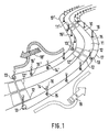
- a winding route section is equipped with the monitoring and information system according to the invention.
- This system comprises three measuring points 12, 12 ', spaced apart from each other in the direction of travel, with a road processor 13, 13' as an evaluation and control unit and lighting elements 14, 14 'arranged on the edge of the road following the course of the road.
- the lighting elements are each equipped with electronics 15, 15 'and signal lights 16, 16' connected to one another to form light chains and form a light bus 17, 17 '.
- the measuring points 12, 12 ' are arranged at different distances from one another in such a way that the distances between adjacent measuring points are larger in the case of a less curvy route, but smaller in the case of a curved route.
- the light chain which extends along the right edge of a lane 11, 11 'and is made up of light elements 14, 14' connected to a light bus 17, 17 ', is used to transmit information to the drivers of the assigned lane.
- the respective directions of travel are indicated by arrows 18, 18 '.
- FIG. 2 shows a section of a route section equipped with the monitoring and information system 20 with two adjacent lanes 21, 21 'for the same direction of travel. The latter are indicated by arrows 22, 22 '.
- this system comprises a measuring point 24, 24' with traffic and load detection devices embedded in the lane transverse to the longitudinal extent of the lane. Furthermore, as also shown in FIG. 1, measuring points of the same configuration are arranged at greater intervals along the road. The measuring points are equipped with axle detectors 25, 25 ', vehicle detectors 26, 26' in the form of induction loops, weighing plates 27, 27 'and dynamic wheel load meters 28, 28'.
- the traffic sensors can also be equipped with environmental sensors not shown in the exemplary embodiment.
- the road and traffic sensors of the adjacent measuring points 24, 24 'of both lanes 21, 21' are each coupled to an evaluation unit in the form of a road processor 30 for detecting the speeds, vehicle classes, vehicle weights and axle weights determined at the detectors of the respective measuring point and for local and If necessary, pairwise and higher-level traffic disturbance calculation using automatic traffic disturbance algorithms.
- a signal processor 32 assigned to the measuring point and with it are connected via a network 33 on both sides along the edge of the road at a distance from each other arranged intelligent lighting elements 34, 34 'with signal lights 35, 35' which are in turn statically or dynamically connected to each other coupled and thus connected to light chains or a light bus 36, 36 '.
- a plurality of measuring points with associated evaluation and control units and light chains coupled therewith are provided at a distance from one another in the direction of travel.
- the road processors 30 associated with the measuring points 24, 24 'spaced along the lane are connected to one another via a communication network 38 and the light chains arranged downstream of the respective signal processor 32 are in turn connected to one another as light buses 36, 36'.
- Each lighting element 34 is equipped with a manually operated emergency switch 40, 40 'which, in the event of an accident or other need, enables the lighting chains to be switched on manually over a distance which is dependent on the course of the route and counter to the direction of travel.
- a traffic disturbance is detected by means of the traffic sensors of a measuring point 24, 24 ', for example the driving of the different road users at very different driving speeds, this is detected by the assigned road processor 30 and automatically recognized on the basis of predetermined traffic disturbance algorithms.
- a road 50 with two adjacent lanes 51, 51 'for opposite directions of travel is equipped with a monitoring and information system which consists of subsystems each comprising a road processor.
- the direction of travel is indicated by arrows 52, 52 '.
- Each subsystem includes two measuring points 53, 53 'and 54, 54' spaced apart from one another in the longitudinal direction of the road, the sensors of which are connected to the assigned road processors 58, 59 via networks 55, 55 'and 56, 56'.
- the road processors assigned to the subsystems which follow one another in the longitudinal direction of the road are connected to one another via a processor network 68 and, moreover, are connected to a power supply 69, which is only indicated.
- Each road processor can also be provided with a modem connection 70 and connected to an optionally available central unit.
- 3 differs from the system structure explained above in connection with FIG. 2 in that the street processors 58, 59 include Appropriate slots for the individual functions are equipped and therefore no separate signal processors are required.
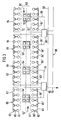
- the road processor 75 illustrated in FIG. 4 is a device in which the individual functional elements are accommodated within a housing 76 which is encapsulated to the outside. Between a power supply 77, which is connected to an external power supply cable 78, and a buffer battery 80, five insertion locations are arranged, in which the various processor cards are accommodated. Thus, the central processor 82 with a leptop interface 83 is located directly next to the power supply 77, and two induction loop processor cards 84, 85, which are followed by an insert 86 for neural processing, are accommodated next to it. Between this insert and the buffer battery 80 there is then an insert 87 designed as an interface card data network, which is connected directly to a data interface modem 88 led out of the housing 76.
- connection modules in the form of modular connection boards and these boards are equipped with terminal strips which provide the direct connection of the processor network, the sensors and a data interface for the signal network.
- the processor network 90 is thus passed through a suitable cable bushing in the outer housing and connected to the connection board 91 which provides the connection to the central processor.
- the connection to the associated sensor system is provided by connecting lines 94, 95 which are passed through cable bushings in the housing and are connected to the terminal strips of these connection boards.
- the signal lines 97, 98 for driving the lighting elements are connected to the remaining connection board 96, which is connected to the data network interface card. Otherwise, the connection modules are equipped with integrated lightning protection.
- the lighting element illustrated in FIG. 5 is a road guide post designed as a lighting post 100.
- This guide post has the typical cross section in the form of an isosceles triangle and is anchored with its lower end on the edge of a road in the ground 101.
- the tip of the triangular guide post cross section formed by the two legs of the triangle points towards the street and the surface facing the oncoming traffic is equipped with a rectangular reflector 102 which extends vertically in its main extension.
- the convertibility from the conventional guide post to the light post 100 is conveyed by a guide post intermediate piece 105 which is designed as a module and which is arranged above the reflector 102 and in the manner shown in FIG. 6, each with a signal light 106, 106 'facing the oncoming and outgoing traffic and with a manually operated push button 107 is provided.
- the guide post intermediate piece has a lower and an upper insertion section 108, 108 ', whose cross sections are adapted to the inner cross section of the guide post.
- the intermediate piece 105 designed as a module is accommodated between the region of the guide post provided with the vertically extending reflector 102 and an upper guide post cap.
- a floor housing 110 with a removable upper cover 111 is arranged in the ground 101, in which the electronics 112 belonging to this light element is accommodated.
- the electronics is connected via a cable network 115 to the electronics of adjacent lighting elements and is connected to the signal lights 106, 106 'arranged in the guide post intermediate piece 105 and the push button 107 via lines 116, 117 and a contact plug 118, which can be used as a removal or Tear-off connector is designed and, in the event of malfunctions or other reasons, allows the guide post intermediate piece to be easily removed with the signal lights and the pushbutton.
- the signal lights of the light post arranged in the guide post intermediate piece 105 are equipped with light area elements 120 in the form of LED arrays. These are LEDs 122 accommodated in a plastic frame 121, which are applied to a circuit board (not shown) in the interest of simple wiring and in the lower part of the plastic frame are shed. Casting the LEDs only in their lower area ensures that their brightness cannot be impaired by dirt when used outdoors because the domes of the LEDs are subject to a natural cleaning effect and the luminous flux is fixed on the domes.
Landscapes
- Physics & Mathematics (AREA)
- General Physics & Mathematics (AREA)
- Traffic Control Systems (AREA)
Applications Claiming Priority (6)
| Application Number | Priority Date | Filing Date | Title |
|---|---|---|---|
| DE4212341 | 1992-04-13 | ||
| DE19924212341 DE4212341A1 (de) | 1992-04-13 | 1992-04-13 | Verfahren zur Überwachung des Straßenverkehrs und zur Information der Verkehrsteilnehmer sowie System zum Durchführen dieses Verfahrens |
| DE4244169 | 1992-12-24 | ||
| DE19924244169 DE4244169A1 (de) | 1992-12-24 | 1992-12-24 | Verkehrsregelungs- und Informationssystem |
| DE19924244393 DE4244393C1 (de) | 1992-12-29 | 1992-12-29 | Verkehrsmeßwerk- und Überwachungssystem |
| DE4244393 | 1992-12-29 |
Publications (3)
| Publication Number | Publication Date |
|---|---|
| EP0565992A2 true EP0565992A2 (fr) | 1993-10-20 |
| EP0565992A3 EP0565992A3 (fr) | 1995-04-12 |
| EP0565992B1 EP0565992B1 (fr) | 2000-06-28 |
Family
ID=27203633
Family Applications (1)
| Application Number | Title | Priority Date | Filing Date |
|---|---|---|---|
| EP93105650A Expired - Lifetime EP0565992B1 (fr) | 1992-04-13 | 1993-04-06 | Procédé et système pour surveiller le trafic et informer les usagers de la voie publique |
Country Status (7)
| Country | Link |
|---|---|
| EP (1) | EP0565992B1 (fr) |
| AT (1) | ATE194245T1 (fr) |
| DE (1) | DE59310065D1 (fr) |
| DK (1) | DK0565992T3 (fr) |
| ES (1) | ES2150924T3 (fr) |
| HU (1) | HUT70249A (fr) |
| PT (1) | PT565992E (fr) |
Cited By (11)
| Publication number | Priority date | Publication date | Assignee | Title |
|---|---|---|---|---|
| EP0860804A3 (fr) * | 1997-02-19 | 2000-05-24 | Giovanni Gualdi | Système de détection et de signalisation d'objets sur la chaussée |
| EP1116172A2 (fr) * | 1998-09-23 | 2001-07-18 | Siemens Aktiengesellschaft | Procede et systeme pour determiner une suite d'actions pour un systeme presentant des etats et selon lequel le passage d'un etat a l'autre intervient suite a une action |
| WO2001097197A1 (fr) * | 2000-06-15 | 2001-12-20 | Coventry University | Dispositif lumineux d'indication de danger |
| DE102005007136A1 (de) * | 2005-02-17 | 2006-08-31 | Rtb Gmbh & Co. Kg | Geschwindigkeitsgesteuerte optische Signalisierungseinrichtung für Verkehrswege |
| CN102956116A (zh) * | 2011-08-23 | 2013-03-06 | 罗伯特·博世有限公司 | 用于突显汽车的期望的运动路径的方法和控制器 |
| CN103310639A (zh) * | 2013-03-19 | 2013-09-18 | 唐国桥 | 道路全程分布的动态交通信号系统 |
| CN105320049A (zh) * | 2015-11-11 | 2016-02-10 | 广东石油化工学院 | 一种新农村道路车辆限重系统及其控制方法 |
| CN106530771A (zh) * | 2017-01-04 | 2017-03-22 | 山东省交通规划设计院 | 一种高速公路主动发光轮廓标交通诱导装置及方法 |
| DE102020001023A1 (de) | 2020-02-18 | 2021-08-19 | Christian Niestolik | Optisches, elektronisches Mehrbereichs- und Orientierungs- und Verkehrsleitsystem |
| CN113628461A (zh) * | 2021-08-09 | 2021-11-09 | 海信集团控股股份有限公司 | 交通监管设备及方法 |
| CN113650601A (zh) * | 2021-09-23 | 2021-11-16 | 上海交通大学 | 车辆控制方法及系统、服务器、车辆 |
Families Citing this family (5)
| Publication number | Priority date | Publication date | Assignee | Title |
|---|---|---|---|---|
| DE102007057818A1 (de) * | 2007-11-30 | 2009-06-04 | Ifn Anwenderzentrum Gmbh | Informationssystem und -einrichtung für die Führer von Fahrzeugen auf Strassen und dergleichen |
| US9018850B2 (en) | 2010-12-28 | 2015-04-28 | GE Lighting Solutions, LLC | Safety flashing detector for traffic lamps |
| US8803704B2 (en) | 2011-03-21 | 2014-08-12 | GE Lighting Solutions, LLC | Traffic signal loading platform |
| US9524641B2 (en) | 2011-03-22 | 2016-12-20 | GE Lighting Solutions, LLC | LED traffic signal fault logging system and method |
| ES2953579A1 (es) * | 2022-04-01 | 2023-11-14 | Cintra Servicios De Infraestructuras S A | Sistema y procedimiento de detección de eventos de tráfico |
Citations (2)
| Publication number | Priority date | Publication date | Assignee | Title |
|---|---|---|---|---|
| DE1516669A1 (de) | 1966-12-02 | 1969-10-09 | Licentia Gmbh | OErtliches Autobahnwarnsystem |
| DE1943596A1 (de) | 1969-08-27 | 1971-03-11 | Standard Elektrik Lorenz Ag | Verfahren zur Weg- und Geschwindigkeitssteuerung von Fahrzeugen |
Family Cites Families (1)
| Publication number | Priority date | Publication date | Assignee | Title |
|---|---|---|---|---|
| DE4039216A1 (de) * | 1990-12-08 | 1992-06-11 | Anschuetz & Co Gmbh | Verfahren zur verstetigung des strassenverkehrs |
-
1993
- 1993-04-06 DE DE59310065T patent/DE59310065D1/de not_active Expired - Lifetime
- 1993-04-06 EP EP93105650A patent/EP0565992B1/fr not_active Expired - Lifetime
- 1993-04-06 ES ES93105650T patent/ES2150924T3/es not_active Expired - Lifetime
- 1993-04-06 AT AT93105650T patent/ATE194245T1/de active
- 1993-04-06 DK DK93105650T patent/DK0565992T3/da active
- 1993-04-06 PT PT93105650T patent/PT565992E/pt unknown
- 1993-04-09 HU HU9301044A patent/HUT70249A/hu unknown
Patent Citations (2)
| Publication number | Priority date | Publication date | Assignee | Title |
|---|---|---|---|---|
| DE1516669A1 (de) | 1966-12-02 | 1969-10-09 | Licentia Gmbh | OErtliches Autobahnwarnsystem |
| DE1943596A1 (de) | 1969-08-27 | 1971-03-11 | Standard Elektrik Lorenz Ag | Verfahren zur Weg- und Geschwindigkeitssteuerung von Fahrzeugen |
Cited By (13)
| Publication number | Priority date | Publication date | Assignee | Title |
|---|---|---|---|---|
| EP0860804A3 (fr) * | 1997-02-19 | 2000-05-24 | Giovanni Gualdi | Système de détection et de signalisation d'objets sur la chaussée |
| EP1116172A2 (fr) * | 1998-09-23 | 2001-07-18 | Siemens Aktiengesellschaft | Procede et systeme pour determiner une suite d'actions pour un systeme presentant des etats et selon lequel le passage d'un etat a l'autre intervient suite a une action |
| WO2001097197A1 (fr) * | 2000-06-15 | 2001-12-20 | Coventry University | Dispositif lumineux d'indication de danger |
| DE102005007136A1 (de) * | 2005-02-17 | 2006-08-31 | Rtb Gmbh & Co. Kg | Geschwindigkeitsgesteuerte optische Signalisierungseinrichtung für Verkehrswege |
| CN102956116B (zh) * | 2011-08-23 | 2018-02-02 | 罗伯特·博世有限公司 | 用于突显汽车的期望的运动路径的方法和控制器 |
| US9493109B2 (en) | 2011-08-23 | 2016-11-15 | Robert Bosch Gmbh | Method and control device for highlighting an expected movement path of a vehicle |
| CN102956116A (zh) * | 2011-08-23 | 2013-03-06 | 罗伯特·博世有限公司 | 用于突显汽车的期望的运动路径的方法和控制器 |
| CN103310639A (zh) * | 2013-03-19 | 2013-09-18 | 唐国桥 | 道路全程分布的动态交通信号系统 |
| CN105320049A (zh) * | 2015-11-11 | 2016-02-10 | 广东石油化工学院 | 一种新农村道路车辆限重系统及其控制方法 |
| CN106530771A (zh) * | 2017-01-04 | 2017-03-22 | 山东省交通规划设计院 | 一种高速公路主动发光轮廓标交通诱导装置及方法 |
| DE102020001023A1 (de) | 2020-02-18 | 2021-08-19 | Christian Niestolik | Optisches, elektronisches Mehrbereichs- und Orientierungs- und Verkehrsleitsystem |
| CN113628461A (zh) * | 2021-08-09 | 2021-11-09 | 海信集团控股股份有限公司 | 交通监管设备及方法 |
| CN113650601A (zh) * | 2021-09-23 | 2021-11-16 | 上海交通大学 | 车辆控制方法及系统、服务器、车辆 |
Also Published As
| Publication number | Publication date |
|---|---|
| HUT70249A (en) | 1995-09-28 |
| PT565992E (pt) | 2000-11-30 |
| EP0565992A3 (fr) | 1995-04-12 |
| DE59310065D1 (de) | 2000-08-03 |
| HU9301044D0 (en) | 1993-06-28 |
| ATE194245T1 (de) | 2000-07-15 |
| ES2150924T3 (es) | 2000-12-16 |
| DK0565992T3 (da) | 2000-10-16 |
| EP0565992B1 (fr) | 2000-06-28 |
Similar Documents
| Publication | Publication Date | Title |
|---|---|---|
| EP0565992B1 (fr) | Procédé et système pour surveiller le trafic et informer les usagers de la voie publique | |
| US5673039A (en) | Method of monitoring vehicular traffic and of providing information to drivers and system for carring out the method | |
| DE3830598C2 (fr) | ||
| EP3540709A1 (fr) | Système de surveillance de route | |
| DE4002337C2 (de) | Warneinrichtung | |
| DE4102381A1 (de) | Stauwarnanlage | |
| DE102014104574B4 (de) | Durchführung von Spezialtransporten | |
| EP1628276A2 (fr) | Système d'assistance pour conducteur d'un véhicule | |
| EP2896028B1 (fr) | Acquisition de donnees de circulation et d'accidentologie a des carrefours de la circulation routiere | |
| DE102020203102A1 (de) | System und Verfahren zur Bereitstellung einer beleuchteten Route für ein sich auf einem Weg bewegendes Objekt | |
| DE202022101961U1 (de) | Intelligentes System zur Steuerung von Strassentransporten zur Abfertigung von Krankenwagen auf der Basis von IOT und künstlicher Intelligenz | |
| DE202021105643U1 (de) | Signalleuchte für das Internet der Dinge mit Überwachungsfunktion | |
| DE4244393C1 (de) | Verkehrsmeßwerk- und Überwachungssystem | |
| DE102020202527A1 (de) | System und Verfahren zur Erfassung und Kommunikation von Informationen für ein Fahrzeug | |
| DE60106138T2 (de) | Verkehrsüberwachungssystem zur rechtzeitigen Signalisierung von Behinderungen in einem Verkehrsnetz | |
| DE202021102226U1 (de) | Verkehrssicherheitssystem | |
| DE10158678B4 (de) | Mobile Lichtsignalanlage und Verfahren zu ihrer Steuerung | |
| DE102007057818A1 (de) | Informationssystem und -einrichtung für die Führer von Fahrzeugen auf Strassen und dergleichen | |
| DE202017007122U1 (de) | Parkplatzüberwachungssystem | |
| WO2009021902A1 (fr) | Procédé et dispositif pour donner la priorité à des véhicules spéciaux à un carrefour réglé par des feux de signalisation | |
| DE4212341A1 (de) | Verfahren zur Überwachung des Straßenverkehrs und zur Information der Verkehrsteilnehmer sowie System zum Durchführen dieses Verfahrens | |
| DE19529079C2 (de) | Einrichtung zur Überwachung von Zugangsbereichen mehrerer Lagergassen | |
| DE29610241U1 (de) | Falschfahrer-Warnanlage | |
| DE69801030T2 (de) | Einrichtung zum Signalisieren von Fahrzeugverkehr auf Autobahnen, Schnellstrassen, Einbahnstrassen und dergleichen | |
| DE4244169A1 (de) | Verkehrsregelungs- und Informationssystem |
Legal Events
| Date | Code | Title | Description |
|---|---|---|---|
| PUAI | Public reference made under article 153(3) epc to a published international application that has entered the european phase |
Free format text: ORIGINAL CODE: 0009012 |
|
| AK | Designated contracting states |
Kind code of ref document: A2 Designated state(s): AT BE CH DE DK ES FR GB IT LI NL PT SE |
|
| PUAL | Search report despatched |
Free format text: ORIGINAL CODE: 0009013 |
|
| AK | Designated contracting states |
Kind code of ref document: A3 Designated state(s): AT BE CH DE DK ES FR GB IT LI NL PT SE |
|
| 17P | Request for examination filed |
Effective date: 19951005 |
|
| RAP1 | Party data changed (applicant data changed or rights of an application transferred) |
Owner name: KIH KOMMUNIKATIONS INDUSTRIE HOLDING AKTIENGESELLS |
|
| 17Q | First examination report despatched |
Effective date: 19980507 |
|
| GRAG | Despatch of communication of intention to grant |
Free format text: ORIGINAL CODE: EPIDOS AGRA |
|
| GRAG | Despatch of communication of intention to grant |
Free format text: ORIGINAL CODE: EPIDOS AGRA |
|
| GRAH | Despatch of communication of intention to grant a patent |
Free format text: ORIGINAL CODE: EPIDOS IGRA |
|
| GRAH | Despatch of communication of intention to grant a patent |
Free format text: ORIGINAL CODE: EPIDOS IGRA |
|
| GRAA | (expected) grant |
Free format text: ORIGINAL CODE: 0009210 |
|
| AK | Designated contracting states |
Kind code of ref document: B1 Designated state(s): AT BE CH DE DK ES FR GB IT LI NL PT SE |
|
| RAP1 | Party data changed (applicant data changed or rights of an application transferred) |
Owner name: PAT GMBH |
|
| REF | Corresponds to: |
Ref document number: 194245 Country of ref document: AT Date of ref document: 20000715 Kind code of ref document: T |
|
| REG | Reference to a national code |
Ref country code: CH Ref legal event code: EP |
|
| REG | Reference to a national code |
Ref country code: CH Ref legal event code: NV Representative=s name: TROESCH SCHEIDEGGER WERNER AG |
|
| GBT | Gb: translation of ep patent filed (gb section 77(6)(a)/1977) |
Effective date: 20000630 |
|
| REF | Corresponds to: |
Ref document number: 59310065 Country of ref document: DE Date of ref document: 20000803 |
|
| ITF | It: translation for a ep patent filed | ||
| ET | Fr: translation filed | ||
| REG | Reference to a national code |
Ref country code: DK Ref legal event code: T3 |
|
| REG | Reference to a national code |
Ref country code: PT Ref legal event code: SC4A Free format text: AVAILABILITY OF NATIONAL TRANSLATION Effective date: 20000829 |
|
| REG | Reference to a national code |
Ref country code: ES Ref legal event code: FG2A Ref document number: 2150924 Country of ref document: ES Kind code of ref document: T3 |
|
| PLBE | No opposition filed within time limit |
Free format text: ORIGINAL CODE: 0009261 |
|
| 26N | No opposition filed | ||
| REG | Reference to a national code |
Ref country code: GB Ref legal event code: IF02 |
|
| REG | Reference to a national code |
Ref country code: GB Ref legal event code: 732E |
|
| REG | Reference to a national code |
Ref country code: PT Ref legal event code: PC4A Free format text: INTERNATIONAL ROAD DYNAMICS INC. CA Effective date: 20040419 |
|
| REG | Reference to a national code |
Ref country code: ES Ref legal event code: PC2A |
|
| REG | Reference to a national code |
Ref country code: FR Ref legal event code: TP |
|
| REG | Reference to a national code |
Ref country code: CH Ref legal event code: PUE Owner name: INTERNATIONAL ROAD DYNAMICS INC. Free format text: PAT GMBH#HERTZSTRASSE 32-34#76275 ETTLINGEN (DE) -TRANSFER TO- INTERNATIONAL ROAD DYNAMICS INC.#702 43RD STREET EAST#SASKATOON, SK S7K 3T9 (CA) Ref country code: CH Ref legal event code: NV Representative=s name: ZIMMERLI, WAGNER & PARTNER AG |
|
| REG | Reference to a national code |
Ref country code: CH Ref legal event code: PFA Owner name: INTERNATIONAL ROAD DYNAMICS INC. Free format text: INTERNATIONAL ROAD DYNAMICS INC.#702 43RD STREET EAST#SASKATOON, SK S7K 3T9 (CA) -TRANSFER TO- INTERNATIONAL ROAD DYNAMICS INC.#702 43RD STREET EAST#SASKATOON, SK S7K 3T9 (CA) |
|
| PGFP | Annual fee paid to national office [announced via postgrant information from national office to epo] |
Ref country code: NL Payment date: 20120413 Year of fee payment: 20 Ref country code: DE Payment date: 20120419 Year of fee payment: 20 Ref country code: DK Payment date: 20120411 Year of fee payment: 20 Ref country code: CH Payment date: 20120412 Year of fee payment: 20 Ref country code: BE Payment date: 20120412 Year of fee payment: 20 |
|
| PGFP | Annual fee paid to national office [announced via postgrant information from national office to epo] |
Ref country code: FR Payment date: 20120504 Year of fee payment: 20 Ref country code: SE Payment date: 20120411 Year of fee payment: 20 Ref country code: GB Payment date: 20120404 Year of fee payment: 20 |
|
| PGFP | Annual fee paid to national office [announced via postgrant information from national office to epo] |
Ref country code: IT Payment date: 20120418 Year of fee payment: 20 |
|
| PGFP | Annual fee paid to national office [announced via postgrant information from national office to epo] |
Ref country code: ES Payment date: 20120510 Year of fee payment: 20 |
|
| PGFP | Annual fee paid to national office [announced via postgrant information from national office to epo] |
Ref country code: PT Payment date: 20120405 Year of fee payment: 20 |
|
| PGFP | Annual fee paid to national office [announced via postgrant information from national office to epo] |
Ref country code: AT Payment date: 20120327 Year of fee payment: 20 |
|
| REG | Reference to a national code |
Ref country code: DK Ref legal event code: EUP |
|
| REG | Reference to a national code |
Ref country code: DE Ref legal event code: R071 Ref document number: 59310065 Country of ref document: DE |
|
| REG | Reference to a national code |
Ref country code: CH Ref legal event code: PL |
|
| REG | Reference to a national code |
Ref country code: PT Ref legal event code: MM4A Free format text: MAXIMUM VALIDITY LIMIT REACHED Effective date: 20130406 |
|
| REG | Reference to a national code |
Ref country code: NL Ref legal event code: V4 Effective date: 20130406 |
|
| BE20 | Be: patent expired |
Owner name: *PAT G.M.B.H. Effective date: 20130406 |
|
| REG | Reference to a national code |
Ref country code: GB Ref legal event code: PE20 Expiry date: 20130405 |
|
| REG | Reference to a national code |
Ref country code: AT Ref legal event code: MK07 Ref document number: 194245 Country of ref document: AT Kind code of ref document: T Effective date: 20130406 |
|
| REG | Reference to a national code |
Ref country code: ES Ref legal event code: FD2A Effective date: 20130702 |
|
| PG25 | Lapsed in a contracting state [announced via postgrant information from national office to epo] |
Ref country code: GB Free format text: LAPSE BECAUSE OF EXPIRATION OF PROTECTION Effective date: 20130405 Ref country code: ES Free format text: LAPSE BECAUSE OF EXPIRATION OF PROTECTION Effective date: 20130407 Ref country code: DE Free format text: LAPSE BECAUSE OF EXPIRATION OF PROTECTION Effective date: 20130409 |
|
| PG25 | Lapsed in a contracting state [announced via postgrant information from national office to epo] |
Ref country code: PT Free format text: LAPSE BECAUSE OF EXPIRATION OF PROTECTION Effective date: 20130416 |