EP0566062A2 - Anzeigevorrichtung - Google Patents
Anzeigevorrichtung Download PDFInfo
- Publication number
- EP0566062A2 EP0566062A2 EP93105973A EP93105973A EP0566062A2 EP 0566062 A2 EP0566062 A2 EP 0566062A2 EP 93105973 A EP93105973 A EP 93105973A EP 93105973 A EP93105973 A EP 93105973A EP 0566062 A2 EP0566062 A2 EP 0566062A2
- Authority
- EP
- European Patent Office
- Prior art keywords
- panels
- bearing
- adjoining
- hinge
- hinge members
- Prior art date
- Legal status (The legal status is an assumption and is not a legal conclusion. Google has not performed a legal analysis and makes no representation as to the accuracy of the status listed.)
- Withdrawn
Links
Images


Classifications
-
- A—HUMAN NECESSITIES
- A47—FURNITURE; DOMESTIC ARTICLES OR APPLIANCES; COFFEE MILLS; SPICE MILLS; SUCTION CLEANERS IN GENERAL
- A47F—SPECIAL FURNITURE, FITTINGS, OR ACCESSORIES FOR SHOPS, STOREHOUSES, BARS, RESTAURANTS OR THE LIKE; PAYING COUNTERS
- A47F5/00—Show stands, hangers, or shelves characterised by their constructional features
- A47F5/10—Adjustable or foldable or dismountable display stands
- A47F5/105—Adjustable partition panels for displaying articles
Definitions
- THIS INVENTION relates to a display system suitable for temporary exhibition displays, for example and which comprises a plurality of panels which are readily connectable and disconnectable for assembly and disassembly of the display, the panels being interconnectable at choice to form any desired one of a variety of display structures.
- Such display systems are known, per se, and typically comprise a plurality of upright poles supported by respective bases and rectangular panels which extend from pole to pole and are clipped or otherwise attached to the respective poles at their respective edges.
- Such known display systems suffer from various disadvantages, ranging from low structural integrity to excessive complexity.
- some such known systems are aesthetically unsatisfactory, for example in having intervening poles, connectors, etc. exposed to view, distracting attention from the advertising or informational material which the display is intended to exhibit.
- such known systems generally suffer from a lack of standardisation in dimensions between components, in some cases inherent in the nature of the components, so that the construction of any but the simplest display structures may require a large number of basically similar but dimensionally slightly different components. It is an object of the invention to provide an improved display system by which the above disadvantages may be avoided or mitigated.
- a display system comprising a plurality of panels interconnected along adjoining sides by interengaging hinge formations comprising respective hinge knuckle or bearing units carried by the respective panels on the respective sides thereof and removable hinge pins extended through cooperating knuckle or bearing units of the adjoining panels to establish connections between the same.
- said panels form part of a modular system wherein the dimensions of each panel, as measured between the axes of respective hinge formations, are equal to a predetermined standard dimension or to an integral multiple thereof.
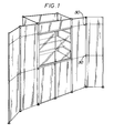
- FIG. 1 is a perspective view of a display constructed using the system of the present invention
- a display system embodying the invention comprises a plurality of panels having predetermined modular dimensions, (as shown in Figure 7) interconnected in such a way as to ensure that the resultant composite structure is also modular - i.e. has dimensions which are a simple integral multiple of the basic modular dimension or dimensions.
- the modular nature of the system is of significance in minimising manufacturing costs and in maximising efficient use of spaces allocated at exhibitions, for example, for such spaces are nowadays often allocated on a modular basis - i.e. the area allocated for each display has its length and breadth determined according to simple multiples of predetermined modular dimensions.
- the system is so arranged as to ensure that interconnections between adjoining panels are made along lines of interconnection which have fixed predetermined positions in relation to the panels themselves, irrespective, so far as possible, of variations in, for example, angular relationships between adjoining panels.
- connection between adjoining panels is by way of hinge members carried by adjoining panels, with the respective line of interconnection between adjoining panels being determined by the pivotal axis of cooperating hinge members, as disclosed in detail below.
- Figure 5 illustrates the form of a single such hinge member, referenced 30.
- Figure 5a is an end elevation view of a member
- Figure 5b is a rear elevation view of the member
- Figure 5c is a side elevation view
- Figure 5d is a front elevation view of member 30.
- Figure 5e is an elevation view from the opposite end from Figure 5a
- Figure 5f is a view in longitudinal section of the member 30.
- such member 30 comprises an elongate body part 32 adapted to be secured to a respective edge of a respective panel proper, the body part 32 having, integrally formed therewith, a laterally projecting ring or eye 34 defining a bearing aperture 36 (see Figure 5a).
- the central axis of the aperture 36 is parallel with the longitudinal dimension of the part 32 and the length of the ring 34, measured along this axis, corresponds with one sixth of the axial length of the part 32 (minus a predetermined dimension for clearance purposes).
- the system utilises three different types of connector elements, each with its respective ring 34 projecting therefrom at a different one of three axial positions along the part 32, as indicated at A, B and C in Figure 5, the pitch between the three positions corresponding to 1/6 of the effective length of the element 32.
- the hinge members, apart from the rings 34, are substantially symmetrical about the median centre line shown extending vertically in Figures 5a, 5b and 5d, it is possible, in effect, to obtain six different locations of ring 34 relative to member 32 taking account of the possibility of reversing the members 30.
- the outer end of the ring 34 has a counter-recess 42 formed therein, which is substantially circular in plan apart from a flat, indicated at 44 in Figure 5a extending chordally across the peripheral wall of the counter-recess.
- This flat 44 cooperates with a complementary flat on a retaining flange at one end of the hinge pin (see Figures 10a to 10d) used to connect cooperating members 30 of adjoining panels together as explained below.
- each panel, referenced 64 comprises a wooden frame with honeycomb core, with skins of MDF or similar material pressed and adhered to the frame.
- the frame is provided with a central groove on the outside edge, on all four sides. This groove, on any such side, may receive a tongue 46 of a connector strip for example of aluminium alloy, having a body portion 48.
- Such connector strips are formed, for example, as extrusions of aluminium alloy having the constant cross section shown in Figure 4.
- Figure 15 shows such a strip, in cross section, in greater detail.
- each member 30 forms a longitudinally extending channel, on the side of the part 32 remote from the ring 34, said channel including an outer region 52 and an inner region 54 separated by inwardly extending ribs 56 on either side of the channel, the part 32 having inwardly projecting flanges 58 which define a restricted longitudinally extending opening to the channel portion 52.
- a transverse web 60 extends across the channel portion 54 for reinforcement purposes.
- the channel portions 52, 54, and the inner edges of ribs 56, 58 preferably converge slightly from the free ends of the part 32 to the plane of web 60.
- the form of the head portion 48 of the connector strip is such as to be received snugly within the channel portion 52 but to project sufficiently far between the ribs 56 to interfere with the web 54. Consequently, whilst a length of connector strip may be extended into a body 32 from either end thereof, the member 32 is not entirely free to slide along the connector strip so that each connector member 32 is located longitudinally with respect to the panels to which it is fitted by two lengths of connector strip extending into the member from either end thereof, to engage the web 60.
- the members 30, with intervening fill members 70 are fitted to the vertical edges of the panels 64 at the upper and lower ends of such edges.
- a respective fill member 70 is slid along each panel vertical edge, on the respective strip 46, 48, to an intermediate position along such edge, leaving end portions of the respective strip 46 and 48 exposed.
- the hinge members 30 are then fitted over the end parts of the respective strips 46, 48 and pushed into their final positions in which their respective webs 60 engage the respective (slightly inset) ends of the respective strips 48.
- the respective members 30 project by half of their axial extent above and below the upper and lower edges of the respective panels.
- the rings 34 in superimposed relationship, of the hinge members of the panels to be interconnected along a common vertical axis, are connected at the upper and lower ends of the panels respectively by upper and lower hinge pins (see below) passed through the aligned rings 34.
- the desired hinge members 30 are preferably interconnected by their respective hinge pins before fitting to the edges of their respective panels.
- each body part 32 externally, has two planar side faces 68 which converge, as shown in end view in Figures 5a and 5c, towards the axis of the ring member 34, the included angle between these side faces being 60 ° or slightly less.
- each fill member 70 has a cross section similar to that of the body portion 32 but, in this case, the mutually inclined side faces actually meet along a line which, in the assembled display, lies on the axis of adjacent members 30.
- the channel parts of the members 70 and the flanges and ribs thereof, which correspond with the channel parts, flanges and ribs of the members 30, have the same references.
- the body part 32 terminates, at its closest approach to the axis of ring member 34, in a concave cylindrical surface centred on that axis and at a radius corresponding substantially with the radius of each ring member 34.
- the panels at each level are assembled before fitting the panels of the next panel above.
- the panels of each row above the first are fitted between the upwardly projecting halves of the members 30 carried by the row of panels below, with the ends of the strips 46, 48 of the upper panels being fitted in the channel parts 52 of the upwardly projecting halves of the members 30 carried by the lower panels.
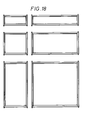
- the preferred display system also includes rectangular frames, in the same modular sizes as the solid panels and which may carry posters, for example or glass or clear plastics "glazing" sheets.
- frames are assembled using extrusions identical with the infill members 70 as the vertical frame members and rails of a cross section shown in Figure 8 as the horizontal frame members.
- the horizontal rails 80 are connected at their ends to the respective members 70 by screw and nut clamping arrangements as illustrated in Figure 12.
- the screws in such screw and nut arrangements may be, for example, hexagon socket screws.
- each horizontal rail 80 comprises two parallel transversely spaced vertical webs 82 connected by an intermediate horizontal web 84 from which project, at positions intermediate the web 82, a pair of upwardly extending inner webs 86 and a pair of downwardly extending inner webs 86, the webs 86 being parallel with the webs 82 and each upwardly extending web 86 being in substantially the same plane as a respective one of the downwardly extending webs 86.
- each web 86 extend upwardly and downwardly slightly further than the webs 82 and each web 86 carries along its free edge a respective flange or lip directed towards the opposing web 86 on the same side as the web 84 whereby there is formed, above and below the web 84 in each member 80, a central channel, (defined between the respective pair of webs 86) having a restricted mouth, bounded on either side by a respective side channel (defined between the respective web 86 and the adjoining part of the adjacent web 80).
- Figures 14a to 14e illustrate one component of the screw and nut connection used to connect an end of a rail 80 to the adjoining member 70.
- This component effectively forms a nut having an elongate rectangular head 90 adapted to fit snugly within the channel part 52 of the member 70 and having a rectangular spigot 92 extending from the head portion 90 at right angles thereto.
- a screw threaded bore extends through the head portion 90 and the spigot 92, along the axis indicated at 94 in Figure 14b to receive a screw 96 (see Figure 12).
- the width of the spigot portion 92 corresponds substantially to the spacing between adjacent webs 86 in the rail 80.
- a horizontal slot extends through the spigot 92 from its free end to a position closely adjacent the head 90.
- each rail 80 is prepared by eliminating the portion of the web 84 lying between the webs 86 over a predetermined distance from the free end of the rail 80 to form, as viewed in plan ( Figure 12) an elongate slot to receive the shank of screw 96, and eliminating the webs 86 and a slightly larger part of the web 84 at an intermediate position along said elongate slot to accommodate the head of the screw 96.
- the shank portion 92 fits snugly between the webs 86, the slot receiving the residual portions of the web 84 between the opposing webs 86.
- the nut 90 thus serves to locate the screw 96 with its axis lying in the plane of the web 84.
- the head 90 With the nut and screw thus assembled to the end of rail 80, the head 90 can be slipped into the channel 52' of the adjoining member 70 from the free end of the latter, whereafter, by tightening the screw 96 using an appropriate tool, for example a hexagonal key, the head portion 90 of the nut may be drawn towards the rail 80 until the flanges 58 of the member 70 are clamped firmly between the head 90 and the end of the rail 80.
- a spigot 81 (see below) may be located relatively loosely by the free end of the shank with the screw 96 extending therethrough an aperture provided in such spigot.
- Lengths of a glazing strip formed as a plastics extrusion of the cross section shown at 100 in Figure 13 (shown to a larger scale in Figure 9) are mounted on the vertical and horizontal members of the frames. These glazing strips are constructed to support plastics or glass glazing panels or other infill panels.
- the extrusion 100 comprises a base portion 102 adapted to fit snugly within the outer portions of the channels defined between opposing webs 86 and likewise to fit in the channel parts 52 of the members 70.
- the extrusion 100 further comprises opposing web formations 104 extending from such base portion 102 and defining a channel to receive plastics or glass glazing strips, or the like.
- Each extrusion 100 has, on each side of its base portion, a respective groove to receive the respective flange of the respective web 86, or the respective flanges 58 of a member 70 whereby each strip of extrusion 100 is held snugly within its respective channel.
- the lengths of extrusion 100 are, of course, fitted into such channels by longitudinal sliding and are so fitted before the frames are assembled. The ends of such strips 100 are mitred as shown in Figure 13a.
- the dimensions of the base portion of the extrusions 100 are such as to provide clearance between the base portions and the nut shanks 92 at the ends of the horizontal rails 80.
- the horizontal beams 80 also provide a means of supporting horizontal members of the system, for example shelves, by providing the latter with downwardly directed hooks or flanges which extend into the outer channels of the rails 80 (defined between the upper webs 86 and the upper portions of the webs 80).
- infill panels 110 may be fitted into such frames by having their edges accommodated within the outer channels of the horizontal rails and abutting or closely approaching the outer faces of the flanges 58 of the members 70.
- the horizontal rails 80 may likewise be utilised to fill in the spaces defined, at the top of the panel assembly, between the upwardly projecting portions, from the uppermost row of panels, of the uppermost members 30.
- the nut and screw clamping arrangement may be used to clamp the ends of the horizontal beams 80 to the members 30 in much the same way as to the members 70 forming the vertical limbs of the rectangular frame.
- a similar provision may be made at the lower ends of the panel assembly.
- the frames shown in Figure 18 have spigots 81 projecting upwardly and downwardly from the upper and lower ends of their respective members 70. These spigots 81 engage in the channel parts 54 of the members 30 fitted to superimposed or underlying panels of the type shown in Figure 7, in an assembled display, or into frames corresponding to those shown in Figure 18 but without such spigots (not shown), or into intervening infill panels.
- the spigots 81 at the top and bottom of a display may also engage in grooves formed in the foot pads 107 or connector caps 107.
- the spigots 81 are inserted into the channel parts 54 of the members 70 from which they project and are retained by the end of the respective screw 96 which projects through a transverse bore 83 in the spigot 81.
- each of the hinge pins referred to comprises a tubular externally cylindrical body or shank 120 dimensioned to fit snugly within the rings 34, a head 122 at one end of the shank which is in the form of a circular plate with a flat cut along one side and is adapted to fit snugly and non-rotatably within the recess 42 in an outermost ring member 34 to be held non-rotatably therein.
- a groove 124 is provided to receive a retaining circlip (not shown).
- the central bore, extending through the shank portion 120 and head 122 is screw threaded from either end of the hinge pin, to receive, where appropriate, a correspondingly screw threaded stud 106 on an upper or lower foot pad or connector cap 107 (according to whether the item 107 shown in Figure 11 is fitted at the upper or lower end of the assembled panel system).
- the screw threaded interengagement between the foot pad or cap and the hinge pin allows for vertical adjustment of the foot pad or cap relative to the remainder of the panel system to adapt to uneven floor surfaces.
- the cap has, on its side nearer the panel system, in use, i.e. the side from which the threaded stud extends, circumferential grooves adapted to receive the projecting portions 31 of the connector body parts 32.
- ceiling panels may be extended between rails 80 carried by transversely spaced panels, at the upper end of the display structure.
- the infill members 70 may be used as trunking to carry electrical cabling unobtrusively (within their inner channels 54).
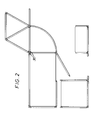
- the preferred system according to the invention allows up to six adjoining panels at the same level to be connected at a common vertical axis, the panels radiating from said axis (see Figure 2).
- the adjacent panels are provided, on their adjacent edges, with respective hinge members 30 having their rings 34 displaced relative to each other, so that, in the assembled condition, the rings 34 of the members 30 of the two panels lie one above the other, the body parts 32 of the adjoining hinge members of the adjoining panels being, of course, at the same level as each other.
Landscapes
- Connection Of Plates (AREA)
Applications Claiming Priority (2)
| Application Number | Priority Date | Filing Date | Title |
|---|---|---|---|
| GB9208459 | 1992-04-16 | ||
| GB929208459A GB9208459D0 (en) | 1992-04-16 | 1992-04-16 | Display system |
Publications (2)
| Publication Number | Publication Date |
|---|---|
| EP0566062A2 true EP0566062A2 (de) | 1993-10-20 |
| EP0566062A3 EP0566062A3 (en) | 1996-02-07 |
Family
ID=10714200
Family Applications (1)
| Application Number | Title | Priority Date | Filing Date |
|---|---|---|---|
| EP93105973A Withdrawn EP0566062A3 (en) | 1992-04-16 | 1993-04-13 | Display system |
Country Status (2)
| Country | Link |
|---|---|
| EP (1) | EP0566062A3 (de) |
| GB (1) | GB9208459D0 (de) |
Cited By (2)
| Publication number | Priority date | Publication date | Assignee | Title |
|---|---|---|---|---|
| FR2713198A1 (fr) * | 1993-12-02 | 1995-06-09 | Prod Cellulosiques Isolants | Profil en U pour le sertissage d'une plaque de carton ou analogue et classeur, boîtier, valisette et présentoir mettant en Óoeuvre un tel profil. |
| WO2008129085A1 (es) * | 2007-04-19 | 2008-10-30 | Iber-Stand, S.L. | Expositor de paneles verticales articulados y/o fijos |
Family Cites Families (6)
| Publication number | Priority date | Publication date | Assignee | Title |
|---|---|---|---|---|
| DE1043060B (de) * | 1956-06-12 | 1958-11-06 | Karl Muehlenbruch | Schau- und Verkaufsvorrichtung fuer verschieden grosse Waren |
| FR1313182A (fr) * | 1961-11-13 | 1962-12-28 | Cotexunion | Paravent perfectionné |
| DE1959874C3 (de) * | 1969-11-28 | 1974-09-12 | Marler Haley Exposystems Ltd., Barnet, Hertfordshire (Grossbritannien) | Ausstellungsmittel |
| GB1400407A (en) * | 1971-06-11 | 1975-07-16 | Wilks R V | Panel system |
| US3931894A (en) * | 1974-01-16 | 1976-01-13 | Murphy Thomas V | Display panel and assembly |
| FR2447701A1 (fr) * | 1979-02-02 | 1980-08-29 | Martinez Georges | Paravent et le moyen d'assemblage et d'articulation des elements ou panneaux le constituant |
-
1992
- 1992-04-16 GB GB929208459A patent/GB9208459D0/en active Pending
-
1993
- 1993-04-13 EP EP93105973A patent/EP0566062A3/en not_active Withdrawn
Cited By (4)
| Publication number | Priority date | Publication date | Assignee | Title |
|---|---|---|---|---|
| FR2713198A1 (fr) * | 1993-12-02 | 1995-06-09 | Prod Cellulosiques Isolants | Profil en U pour le sertissage d'une plaque de carton ou analogue et classeur, boîtier, valisette et présentoir mettant en Óoeuvre un tel profil. |
| WO2008129085A1 (es) * | 2007-04-19 | 2008-10-30 | Iber-Stand, S.L. | Expositor de paneles verticales articulados y/o fijos |
| ES2306608A1 (es) * | 2007-04-19 | 2008-11-01 | Iber-Stand, S.L. | Expositor de paneles verticales articulados y/o fijos. |
| ES2306608B1 (es) * | 2007-04-19 | 2009-09-16 | Iber-Stand, S.L. | Expositor de paneles verticales articulados y/o fijos. |
Also Published As
| Publication number | Publication date |
|---|---|
| GB9208459D0 (en) | 1992-06-03 |
| EP0566062A3 (en) | 1996-02-07 |
Similar Documents
| Publication | Publication Date | Title |
|---|---|---|
| US7165360B2 (en) | Modular room system and method | |
| US7185460B2 (en) | Free-standing panel wall system | |
| US5640816A (en) | Freestanding modular changing room system | |
| US7096637B2 (en) | Display structure and system | |
| CA2932170C (en) | Method of configuring walls | |
| US4545142A (en) | Display framing apparatus | |
| US5305571A (en) | Structural frame assembly | |
| US20020112443A1 (en) | Method of connecting partition panels | |
| US20020023391A1 (en) | Wall and display systems and components | |
| NZ191240A (en) | Panel support apparatus:article of furniture | |
| WO2015188105A1 (en) | Straight and curved reconfigurable partition systems | |
| US4549712A (en) | Apparatus for mounting a device on a slotted post | |
| US20140034596A1 (en) | Modular exhibit structure | |
| US4813196A (en) | Structural system | |
| US5421112A (en) | Modular display assembly | |
| WO1987003321A1 (en) | Panel structures | |
| EP0546492A2 (de) | Vorrichtung für Anzeigetafeln | |
| US4676469A (en) | Composite bar section | |
| EP0566062A2 (de) | Anzeigevorrichtung | |
| US5085155A (en) | Shelf assembly | |
| GB2142058A (en) | Panel securing device | |
| US6052950A (en) | Modular structure having an elevated load-bearing surface | |
| EP0288996A2 (de) | Ein Anzeigesystem | |
| CA2938880A1 (en) | Method of configuring walls | |
| NZ302193A (en) | Panel and method of connecting two adjacent panels - panels moved in a longitudinal direction to engage prior to lateral movement |
Legal Events
| Date | Code | Title | Description |
|---|---|---|---|
| PUAI | Public reference made under article 153(3) epc to a published international application that has entered the european phase |
Free format text: ORIGINAL CODE: 0009012 |
|
| AK | Designated contracting states |
Kind code of ref document: A2 Designated state(s): BE CH DE DK ES FR GB IT LI NL SE |
|
| PUAL | Search report despatched |
Free format text: ORIGINAL CODE: 0009013 |
|
| AK | Designated contracting states |
Kind code of ref document: A3 Designated state(s): BE CH DE DK ES FR GB IT LI NL SE |
|
| 17P | Request for examination filed |
Effective date: 19960805 |
|
| 17Q | First examination report despatched |
Effective date: 19970526 |
|
| 18D | Application deemed to be withdrawn |
Effective date: 19971007 |