EP0566176A1 - Dispositif pour couper des légumes, par exemple pommes de terre - Google Patents
Dispositif pour couper des légumes, par exemple pommes de terre Download PDFInfo
- Publication number
- EP0566176A1 EP0566176A1 EP93200844A EP93200844A EP0566176A1 EP 0566176 A1 EP0566176 A1 EP 0566176A1 EP 93200844 A EP93200844 A EP 93200844A EP 93200844 A EP93200844 A EP 93200844A EP 0566176 A1 EP0566176 A1 EP 0566176A1
- Authority
- EP
- European Patent Office
- Prior art keywords
- coupling piece
- cutting mechanism
- pipe
- pipe part
- directing means
- Prior art date
- Legal status (The legal status is an assumption and is not a legal conclusion. Google has not performed a legal analysis and makes no representation as to the accuracy of the status listed.)
- Granted
Links
- 230000007246 mechanism Effects 0.000 claims abstract description 41
- 230000008878 coupling Effects 0.000 claims abstract description 29
- 238000010168 coupling process Methods 0.000 claims abstract description 29
- 238000005859 coupling reaction Methods 0.000 claims abstract description 29
- 239000012530 fluid Substances 0.000 claims abstract description 7
- 235000002595 Solanum tuberosum Nutrition 0.000 claims abstract description 6
- 244000061456 Solanum tuberosum Species 0.000 claims abstract description 6
- 235000012015 potatoes Nutrition 0.000 claims abstract description 6
- 238000005192 partition Methods 0.000 claims description 13
- 238000011144 upstream manufacturing Methods 0.000 claims description 4
- 238000010276 construction Methods 0.000 claims description 3
- 239000000463 material Substances 0.000 claims description 2
- 210000005069 ears Anatomy 0.000 description 5
- XLYOFNOQVPJJNP-UHFFFAOYSA-N water Substances O XLYOFNOQVPJJNP-UHFFFAOYSA-N 0.000 description 4
- 230000000694 effects Effects 0.000 description 2
- 230000002411 adverse Effects 0.000 description 1
- 230000006835 compression Effects 0.000 description 1
- 238000007906 compression Methods 0.000 description 1
- 230000007423 decrease Effects 0.000 description 1
- 238000012423 maintenance Methods 0.000 description 1
- 230000000284 resting effect Effects 0.000 description 1
Images


Classifications
-
- B—PERFORMING OPERATIONS; TRANSPORTING
- B65—CONVEYING; PACKING; STORING; HANDLING THIN OR FILAMENTARY MATERIAL
- B65G—TRANSPORT OR STORAGE DEVICES, e.g. CONVEYORS FOR LOADING OR TIPPING, SHOP CONVEYOR SYSTEMS OR PNEUMATIC TUBE CONVEYORS
- B65G53/00—Conveying materials in bulk through troughs, pipes or tubes by floating the materials or by flow of gas, liquid or foam
- B65G53/34—Details
- B65G53/52—Adaptations of pipes or tubes
- B65G53/56—Switches
-
- B—PERFORMING OPERATIONS; TRANSPORTING
- B26—HAND CUTTING TOOLS; CUTTING; SEVERING
- B26D—CUTTING; DETAILS COMMON TO MACHINES FOR PERFORATING, PUNCHING, CUTTING-OUT, STAMPING-OUT OR SEVERING
- B26D7/00—Details of apparatus for cutting, cutting-out, stamping-out, punching, perforating, or severing by means other than cutting
- B26D7/06—Arrangements for feeding or delivering work of other than sheet, web, or filamentary form
- B26D7/0658—Arrangements for feeding or delivering work of other than sheet, web, or filamentary form using fluid, e.g. hydraulic, acting directly on the work
Definitions
- the invention relates to a device for cutting tuberous crops, such as potatoes, said device being provided with a frame and with a pipe supported by said frame, through which a fluid with tuberous crops present therein can be pumped by means of a pump, whilst a cutting mechanism is accommodated within said pipe and a directing means is provided between two pipe parts in the pipe, upstream of the cutting mechanism, said directing means bridging the gap between the facing ends of the pipe parts and being provided with a jacket of a flexible material, which comprises a passage which narrows in the direction of flow.
- Such a device is known from DE-A-1186673.
- the jacket is clamped down by means of a flange and bolts on the wall of a casing accommodating the jacket near one end.
- the mouth of the other end is located near an opening provided in the casing, to which a pipe part containing the cutting mechanism is connected.
- the directing means comprising the jacket can only be removed by dismounting a considerable part of the device. In addition to that there will be leakage losses, which will have an adverse effect on the efficiency of the device.
- the directing means is provided with flanges near its ends, whilst hold-down means are secured to the frame between said flanges, said hold-down means being used to press the flanges against corresponding abutting surfaces provided on the facing ends of the pipe parts.
- the directing means can be locked in position in the device and be detached in a simple manner, so that the directing means can be mounted and removed quickly and simply, which will considerably facilitate any necessary maintenance work on the device. Furthermore any leakage losses near the directing means are excluded.
- Figure 1 is a diagrammatic perspective view of a device according to the invention.
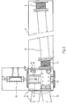
- Figure 2 is a larger-scale plan view of the adjustable pipe part.
- Figure 3 is a larger-scale cross-sectional view of Figure 2.
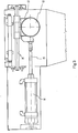
- Figure 4 is a plan view of a directing means and a cutting mechanism positioned therebehind.
- Figure 5 is a side view of Figure 4, wherein certain parts have been left out for easy reference.
- the device according to the invention shown in Figure 1 comprises a frame 1, which supports a trough 2, which opens into a reservoir 3, in which the tuberous crops to be cut, such as for example potatoes, are supplied (in a manner not shown) to the water contained therein.
- the reservoir 3 is connected to the suction side of a pump 5 by means of a connecting pipe 4, which pump can be driven by means of a motor 6.
- a pipe part 7 is connected to the delivery side of the pump 5, said pipe part 7 at its end remote from the pump connecting to a resilient bellows 8 (Figure 2), which is accommodated in a casing 9 supported by the frame.
- the bellows 8 forms the connection between the pipe part 7 and a further pipe part 10.
- the pipe part 10 is connected, through a resilient bellows 11, to a coupling piece 13 provided with a passage 12.
- Said coupling piece 13 is movably supported by means of two rods 14 secured to the walls of the casing 9, said rods crossing the longitudinal axis of the passage 12 perpendicularly.
- the pipe parts 18 and 19 connect to stubs 20 and 21 respectively with their ends remote from the casing 9, said stubs being secured to an upright partition 23 of a casing 24.
- Two directing means 25 are located inside the casing 24, only one being shown in Figure 4, the other being located under a cover 26 closing the respective part of the casing 24 at its upper side.
- the directing means 25 comprises two flanges 27 and 28, a rubber hose 29 (only diagrammatically indicated) extending between said flanges.
- Ears 30 are secured to the flange 27, said ears accommodating vertically extending pivot pins 31.
- Connecting blocks 32 are pivotable about said pivot pins 31, plates 33 surrounding said rubber hose being secured to said connecting blocks.
- the diameter of the hose 29 gradually decreases in downstream direction and the shape of the plates or wings 33 surrounding the hose is adapted thereto.
- each rod 35 extending parallel to the central axis of the hose 29 are journalled so as to have lengthwise movement in ears 34 secured to walls of the casing 24.
- the rods 35 When seen in plan view the rods 35 are thereby arranged in pairs, being in line with each other, on either side of the directing means 25.
- An air bellows 36 is disposed between each pair of aligned rods 35.
- each rod 35 is surrounded by a compression spring 37, which is confined between an ear 34 supporting the respective rod and a ring 38 secured to said rod.
- the ends of the rods 35 remote from the bellows 36 are located opposite ears 38 and 39 secured to the flanges 27 and 28 respectively.
- arms 41 are disposed beside the directing means, when seen in plan view, said arms each being connected near one end to a vertical pivot pin 42.
- the free ends of the arms support rollers 43.
- the pivot pins 42 are connected to arms 44 extending transversely to the arms 41.
- Pins 45 are secured to the free ends of the arms 44, said pins extending into a block 46.
- the sliding block 46 is secured to a rod 47, which is movable against the spring force exerted by a spring 49 surrounding the rod 47 when a pressurized fluid is supplied to the bellows.
- a block-shaped cutting mechanism 50 abuts against the side of the partition 40 remote from the directing means, said cutting mechanism resting on supports 51 provided in the casing 24.
- the block-shaped cutting mechanism 50 conventionally comprises a passage, in which cutting means are provided for cutting tuberous crops, such as potatoes, into desired chips, slices or the like.
- a tube section 52 At the side remote from the partition 40 the end of a tube section 52 abuts against the cutting mechanism 50, said tube section being slidably accommodated in a further tube section 53, which is secured to a partition 54 of the casing 24.
- a stub 55 is connected to the outer side of the casing, said stub being connected to a discharge pipe 56 ( Figure 1).
- Lever arms 59 are pivotable about the pins 58, the ends of said lever arms 59 being interconnected by means of a cross rod 60 forming a grip.
- a downwardly extending ear 61 is secured to each of the lever arms 59.
- One end of a coupling plate 63 is pivotably coupled to the ear 61 of the respective lever arm 59 by means of a pin 62 extending parallel to the pins 58.
- the other end of the coupling plate 63 is coupled to the end of the tube section 52 directed towards the cutting mechanism 50 by means of a pin 64 extending parallel to the pin 62.
- Said latter end of the tube section 52 is provided with a flange 65, which engagingly surrounds the end of the cutting mechanism 50 directed towards the flange with a protruding collar.
- the central axes of the pins 64 intersect the central axis of the passage through the tube section 52 perpendicularly, whilst in this illustrated operating position the central axes of the pins 62 are located under the plane through the central axes of the pins 64 and 58. In this position an adjusting bolt 68 secured to a lever arm 59 is furthermore supported on the coupling plate 63, so that the lever 59 cannot be pressed down any further.
- the cutting mechanism can thus be readily exchanged for another cutting mechanism, which can be placed on the supporting strips 51 in the position shown in Figure 5 again.
- the levers 59 can be pivoted in a direction opposed to the arrow A again, whereby the flange 65 of the sleeve 52 will be pressed firmly against the end of the cutting mechanism 50 again and whereby the cutting mechanism 50 will be pressed firmly against the partition 40, whilst after passing the aforesaid dead centre the mounting mechanism for the cutting mechanism 50 will be locked and the cutting mechanism 50 will not be unlocked before a force is exerted on the levers 59 in the direction according to arrow A.
- the fluid usually water
- the tuberous crops present therein such as potatoes
- the fluid will be sucked in from the reservoir 3 by the pump and, with the arrangement shown in Figure 1, be pumped into the pipe part 18 through the pipe parts 7 and 10 and the connecting piece 13.
- the flow will take place through the directing means 25 connected to the pipe part 18, in which the tuberous crops are oriented in such a manner that in lengthwise they extend at least substantially parallel to the direction of flow, in order to be moved through the cutting mechanism 50 in this position.
- the chipped products move from the cutting mechanism 50 into the discharge pipe 56, which discharges the product towards a screen (not shown), where the chipped products and the water are separated, whereby the separated water can be led back to the reservoir 3 via the trough 2.
- the connecting piece 13 can be moved from the position shown in the Figures in such a manner, that the pipe part 10 is put into communication with the pipe part 19, so that an unimpeded passage of the tuberous crops through the device can be effected.
- both the directing means and the cutting mechanism can be readily detached or locked in position, so that a quick detachment or mounting of both a directing mechanism and a cutting mechanism can be realized.
Landscapes
- Engineering & Computer Science (AREA)
- Mechanical Engineering (AREA)
- Life Sciences & Earth Sciences (AREA)
- Forests & Forestry (AREA)
- Apparatuses For Bulk Treatment Of Fruits And Vegetables And Apparatuses For Preparing Feeds (AREA)
- Harvesting Machines For Root Crops (AREA)
- Preparation Of Fruits And Vegetables (AREA)
- Control And Other Processes For Unpacking Of Materials (AREA)
- Harvesting Machines For Specific Crops (AREA)
- Sowing (AREA)
- Pretreatment Of Seeds And Plants (AREA)
Applications Claiming Priority (2)
| Application Number | Priority Date | Filing Date | Title |
|---|---|---|---|
| NL9200545 | 1992-03-25 | ||
| NL9200545A NL9200545A (nl) | 1992-03-25 | 1992-03-25 | Inrichting voor het snijden van knolgewassen. |
Publications (2)
| Publication Number | Publication Date |
|---|---|
| EP0566176A1 true EP0566176A1 (fr) | 1993-10-20 |
| EP0566176B1 EP0566176B1 (fr) | 1996-08-21 |
Family
ID=19860603
Family Applications (1)
| Application Number | Title | Priority Date | Filing Date |
|---|---|---|---|
| EP93200844A Expired - Lifetime EP0566176B1 (fr) | 1992-03-25 | 1993-03-24 | Dispositif pour couper des légumes, par exemple pommes de terre |
Country Status (5)
| Country | Link |
|---|---|
| EP (1) | EP0566176B1 (fr) |
| AT (1) | ATE141542T1 (fr) |
| DE (1) | DE69304114T2 (fr) |
| DK (1) | DK0566176T3 (fr) |
| NL (1) | NL9200545A (fr) |
Cited By (2)
| Publication number | Priority date | Publication date | Assignee | Title |
|---|---|---|---|---|
| GB2543797A (en) * | 2015-10-28 | 2017-05-03 | Vanmark Equipment Llc | Apparatus for diverting solid food pieces suspended in a flowing liquid |
| US10335971B2 (en) | 2015-10-28 | 2019-07-02 | Vanmark Equipment Llc | Apparatus for diverting solid food pieces suspended in a flowing liquid |
Citations (4)
| Publication number | Priority date | Publication date | Assignee | Title |
|---|---|---|---|---|
| US2586144A (en) * | 1950-07-08 | 1952-02-19 | Henry F Benoit | Stock switch |
| DE1186673B (de) * | 1963-10-29 | 1965-02-04 | Lamb Weston Inc | Vorrichtung zum Schneiden von Waren, z. B. rohen Kartoffeln, in vorgegebene Groessen |
| FR2189656A1 (fr) * | 1972-06-21 | 1974-01-25 | Simon Ltd Henry | |
| US4157848A (en) * | 1977-12-27 | 1979-06-12 | Smoot Co. | Diverter valve |
-
1992
- 1992-03-25 NL NL9200545A patent/NL9200545A/nl not_active Application Discontinuation
-
1993
- 1993-03-24 DK DK93200844.4T patent/DK0566176T3/da active
- 1993-03-24 DE DE69304114T patent/DE69304114T2/de not_active Expired - Fee Related
- 1993-03-24 EP EP93200844A patent/EP0566176B1/fr not_active Expired - Lifetime
- 1993-03-24 AT AT93200844T patent/ATE141542T1/de not_active IP Right Cessation
Patent Citations (4)
| Publication number | Priority date | Publication date | Assignee | Title |
|---|---|---|---|---|
| US2586144A (en) * | 1950-07-08 | 1952-02-19 | Henry F Benoit | Stock switch |
| DE1186673B (de) * | 1963-10-29 | 1965-02-04 | Lamb Weston Inc | Vorrichtung zum Schneiden von Waren, z. B. rohen Kartoffeln, in vorgegebene Groessen |
| FR2189656A1 (fr) * | 1972-06-21 | 1974-01-25 | Simon Ltd Henry | |
| US4157848A (en) * | 1977-12-27 | 1979-06-12 | Smoot Co. | Diverter valve |
Cited By (3)
| Publication number | Priority date | Publication date | Assignee | Title |
|---|---|---|---|---|
| GB2543797A (en) * | 2015-10-28 | 2017-05-03 | Vanmark Equipment Llc | Apparatus for diverting solid food pieces suspended in a flowing liquid |
| US10335971B2 (en) | 2015-10-28 | 2019-07-02 | Vanmark Equipment Llc | Apparatus for diverting solid food pieces suspended in a flowing liquid |
| GB2543797B (en) * | 2015-10-28 | 2020-04-29 | Vanmark Equipment Llc | Apparatus for diverting solid food pieces suspended in a flowing liquid |
Also Published As
| Publication number | Publication date |
|---|---|
| DK0566176T3 (da) | 1996-12-02 |
| NL9200545A (nl) | 1993-10-18 |
| ATE141542T1 (de) | 1996-09-15 |
| EP0566176B1 (fr) | 1996-08-21 |
| DE69304114D1 (de) | 1996-09-26 |
| DE69304114T2 (de) | 1997-01-23 |
Similar Documents
| Publication | Publication Date | Title |
|---|---|---|
| EP0566176B1 (fr) | Dispositif pour couper des légumes, par exemple pommes de terre | |
| US5074143A (en) | Cart for removing and installing dies in a cut-off press | |
| US20010042428A1 (en) | Tensive cutting assembly | |
| DE2145571C3 (de) | Schlauchquetschpumpe | |
| SU1195920A3 (ru) | Двухцилиндровый шламовый насос | |
| US4170253A (en) | Bakery mix dispenser having pump actuated outlet gate | |
| CN211806353U (zh) | 一种香肠加工切片装置 | |
| CN112519295A (zh) | 一种废金属自动化打包流水生产线及其打包方法 | |
| US3975992A (en) | Lift control system for press unloader or the like | |
| US3908537A (en) | Vacuumizing apparatus | |
| KR20030005233A (ko) | 수분 함유 제품의 압출용 장치 | |
| US5219319A (en) | Apparatus for replacing tool sets of powder molding press | |
| US5586494A (en) | Swivelling piston press | |
| CN109368275A (zh) | 一种卸料阀 | |
| US3711223A (en) | Hydraulic control system for concrete placer | |
| US5514031A (en) | Automated leg shear with bi-directional cutting arm | |
| US4173436A (en) | Pivotable pipe slide for use in a two cylinder concrete pump | |
| CN223759183U (zh) | 一种鲜湿米粉分流装置 | |
| DE59910805D1 (de) | Stufenloses automatisch-mechanisches Schaum-Dosiersystem für Hoch- und Normaldruck Feuerlöschkreiselpumpen | |
| EP0291829A3 (en) | Hopper for a pneumatic suction or pressure conveyor system | |
| US2697006A (en) | Liquid handling machine for log debarking | |
| CN221187482U (zh) | 一种医用引流袋成型装置 | |
| US6896018B2 (en) | Vacuum flitch table system | |
| CN114572671A (zh) | 一种奶茶输送拨料装置 | |
| JPH07332510A (ja) | 流体用バルブ装置 |
Legal Events
| Date | Code | Title | Description |
|---|---|---|---|
| PUAI | Public reference made under article 153(3) epc to a published international application that has entered the european phase |
Free format text: ORIGINAL CODE: 0009012 |
|
| AK | Designated contracting states |
Kind code of ref document: A1 Designated state(s): AT BE CH DE DK ES FR GB GR IE IT LI LU MC NL PT SE |
|
| 17P | Request for examination filed |
Effective date: 19940411 |
|
| 17Q | First examination report despatched |
Effective date: 19950711 |
|
| GRAG | Despatch of communication of intention to grant |
Free format text: ORIGINAL CODE: EPIDOS AGRA |
|
| GRAH | Despatch of communication of intention to grant a patent |
Free format text: ORIGINAL CODE: EPIDOS IGRA |
|
| GRAH | Despatch of communication of intention to grant a patent |
Free format text: ORIGINAL CODE: EPIDOS IGRA |
|
| GRAA | (expected) grant |
Free format text: ORIGINAL CODE: 0009210 |
|
| AK | Designated contracting states |
Kind code of ref document: B1 Designated state(s): AT BE CH DE DK ES FR GB GR IE IT LI LU MC NL PT SE |
|
| PG25 | Lapsed in a contracting state [announced via postgrant information from national office to epo] |
Ref country code: GR Free format text: LAPSE BECAUSE OF FAILURE TO SUBMIT A TRANSLATION OF THE DESCRIPTION OR TO PAY THE FEE WITHIN THE PRESCRIBED TIME-LIMIT Effective date: 19960821 Ref country code: ES Free format text: THE PATENT HAS BEEN ANNULLED BY A DECISION OF A NATIONAL AUTHORITY Effective date: 19960821 |
|
| REF | Corresponds to: |
Ref document number: 141542 Country of ref document: AT Date of ref document: 19960915 Kind code of ref document: T |
|
| REG | Reference to a national code |
Ref country code: CH Ref legal event code: NV Representative=s name: BOVARD AG PATENTANWAELTE |
|
| REG | Reference to a national code |
Ref country code: IE Ref legal event code: FG4D Free format text: 69497 |
|
| REF | Corresponds to: |
Ref document number: 69304114 Country of ref document: DE Date of ref document: 19960926 |
|
| ITF | It: translation for a ep patent filed | ||
| REG | Reference to a national code |
Ref country code: CH Ref legal event code: PFA Free format text: KIREMKO B.V.,STEENOVENWEG 9 P.O. BOX 5,NL-3417 ZG MONTFOORT (NL) TRANSFER- KIREMKO B.V.,TASVELD 7, POSTBUS 5,3417 ZG MONTFOORT (NL) |
|
| RAP2 | Party data changed (patent owner data changed or rights of a patent transferred) |
Owner name: KIREMKO B.V. |
|
| PG25 | Lapsed in a contracting state [announced via postgrant information from national office to epo] |
Ref country code: PT Effective date: 19961121 |
|
| REG | Reference to a national code |
Ref country code: DK Ref legal event code: T3 |
|
| ET | Fr: translation filed |
Free format text: CORRECTIONS |
|
| NLT2 | Nl: modifications (of names), taken from the european patent patent bulletin |
Owner name: KIREMKO B.V. |
|
| PG25 | Lapsed in a contracting state [announced via postgrant information from national office to epo] |
Ref country code: IE Free format text: LAPSE BECAUSE OF NON-PAYMENT OF DUE FEES Effective date: 19970324 |
|
| PLBE | No opposition filed within time limit |
Free format text: ORIGINAL CODE: 0009261 |
|
| STAA | Information on the status of an ep patent application or granted ep patent |
Free format text: STATUS: NO OPPOSITION FILED WITHIN TIME LIMIT |
|
| 26N | No opposition filed | ||
| PG25 | Lapsed in a contracting state [announced via postgrant information from national office to epo] |
Ref country code: MC Effective date: 19970930 |
|
| PGFP | Annual fee paid to national office [announced via postgrant information from national office to epo] |
Ref country code: LU Payment date: 19991224 Year of fee payment: 8 |
|
| PGFP | Annual fee paid to national office [announced via postgrant information from national office to epo] |
Ref country code: DE Payment date: 20000128 Year of fee payment: 8 |
|
| PGFP | Annual fee paid to national office [announced via postgrant information from national office to epo] |
Ref country code: BE Payment date: 20000208 Year of fee payment: 8 |
|
| PGFP | Annual fee paid to national office [announced via postgrant information from national office to epo] |
Ref country code: DK Payment date: 20000317 Year of fee payment: 8 |
|
| PGFP | Annual fee paid to national office [announced via postgrant information from national office to epo] |
Ref country code: SE Payment date: 20000320 Year of fee payment: 8 Ref country code: GB Payment date: 20000320 Year of fee payment: 8 |
|
| PGFP | Annual fee paid to national office [announced via postgrant information from national office to epo] |
Ref country code: AT Payment date: 20000324 Year of fee payment: 8 |
|
| PGFP | Annual fee paid to national office [announced via postgrant information from national office to epo] |
Ref country code: FR Payment date: 20000327 Year of fee payment: 8 |
|
| PGFP | Annual fee paid to national office [announced via postgrant information from national office to epo] |
Ref country code: NL Payment date: 20000329 Year of fee payment: 8 |
|
| PGFP | Annual fee paid to national office [announced via postgrant information from national office to epo] |
Ref country code: CH Payment date: 20010305 Year of fee payment: 9 |
|
| PG25 | Lapsed in a contracting state [announced via postgrant information from national office to epo] |
Ref country code: LU Free format text: LAPSE BECAUSE OF NON-PAYMENT OF DUE FEES Effective date: 20010324 Ref country code: GB Free format text: LAPSE BECAUSE OF NON-PAYMENT OF DUE FEES Effective date: 20010324 Ref country code: DK Free format text: LAPSE BECAUSE OF NON-PAYMENT OF DUE FEES Effective date: 20010324 Ref country code: AT Free format text: LAPSE BECAUSE OF NON-PAYMENT OF DUE FEES Effective date: 20010324 |
|
| PG25 | Lapsed in a contracting state [announced via postgrant information from national office to epo] |
Ref country code: SE Free format text: LAPSE BECAUSE OF NON-PAYMENT OF DUE FEES Effective date: 20010325 |
|
| PG25 | Lapsed in a contracting state [announced via postgrant information from national office to epo] |
Ref country code: BE Free format text: LAPSE BECAUSE OF NON-PAYMENT OF DUE FEES Effective date: 20010331 |
|
| BERE | Be: lapsed |
Owner name: KIREMKO B.V. Effective date: 20010331 |
|
| PG25 | Lapsed in a contracting state [announced via postgrant information from national office to epo] |
Ref country code: NL Free format text: LAPSE BECAUSE OF NON-PAYMENT OF DUE FEES Effective date: 20011001 |
|
| EUG | Se: european patent has lapsed |
Ref document number: 93200844.4 |
|
| GBPC | Gb: european patent ceased through non-payment of renewal fee |
Effective date: 20010324 |
|
| REG | Reference to a national code |
Ref country code: DK Ref legal event code: EBP |
|
| PG25 | Lapsed in a contracting state [announced via postgrant information from national office to epo] |
Ref country code: FR Free format text: LAPSE BECAUSE OF NON-PAYMENT OF DUE FEES Effective date: 20011130 |
|
| NLV4 | Nl: lapsed or anulled due to non-payment of the annual fee |
Effective date: 20011001 |
|
| REG | Reference to a national code |
Ref country code: FR Ref legal event code: ST |
|
| PG25 | Lapsed in a contracting state [announced via postgrant information from national office to epo] |
Ref country code: DE Free format text: LAPSE BECAUSE OF NON-PAYMENT OF DUE FEES Effective date: 20020101 |
|
| PG25 | Lapsed in a contracting state [announced via postgrant information from national office to epo] |
Ref country code: LI Free format text: LAPSE BECAUSE OF NON-PAYMENT OF DUE FEES Effective date: 20020331 Ref country code: CH Free format text: LAPSE BECAUSE OF NON-PAYMENT OF DUE FEES Effective date: 20020331 |
|
| REG | Reference to a national code |
Ref country code: CH Ref legal event code: PL |
|
| PG25 | Lapsed in a contracting state [announced via postgrant information from national office to epo] |
Ref country code: IT Free format text: LAPSE BECAUSE OF NON-PAYMENT OF DUE FEES Effective date: 20050324 |