EP0566236A1 - Amplicateur optique avec spectre de gain automatiquement auto-ajustable - Google Patents
Amplicateur optique avec spectre de gain automatiquement auto-ajustable Download PDFInfo
- Publication number
- EP0566236A1 EP0566236A1 EP93301692A EP93301692A EP0566236A1 EP 0566236 A1 EP0566236 A1 EP 0566236A1 EP 93301692 A EP93301692 A EP 93301692A EP 93301692 A EP93301692 A EP 93301692A EP 0566236 A1 EP0566236 A1 EP 0566236A1
- Authority
- EP
- European Patent Office
- Prior art keywords
- optical
- signals
- fibre
- optical amplifier
- gain medium
- Prior art date
- Legal status (The legal status is an assumption and is not a legal conclusion. Google has not performed a legal analysis and makes no representation as to the accuracy of the status listed.)
- Granted
Links
Images

Classifications
-
- H—ELECTRICITY
- H01—ELECTRIC ELEMENTS
- H01S—DEVICES USING THE PROCESS OF LIGHT AMPLIFICATION BY STIMULATED EMISSION OF RADIATION [LASER] TO AMPLIFY OR GENERATE LIGHT; DEVICES USING STIMULATED EMISSION OF ELECTROMAGNETIC RADIATION IN WAVE RANGES OTHER THAN OPTICAL
- H01S3/00—Lasers, i.e. devices using stimulated emission of electromagnetic radiation in the infrared, visible or ultraviolet wave range
- H01S3/10—Controlling the intensity, frequency, phase, polarisation or direction of the emitted radiation, e.g. switching, gating, modulating or demodulating
- H01S3/10007—Controlling the intensity, frequency, phase, polarisation or direction of the emitted radiation, e.g. switching, gating, modulating or demodulating in optical amplifiers
- H01S3/10023—Controlling the intensity, frequency, phase, polarisation or direction of the emitted radiation, e.g. switching, gating, modulating or demodulating in optical amplifiers by functional association of additional optical elements, e.g. filters, gratings, reflectors
-
- H—ELECTRICITY
- H01—ELECTRIC ELEMENTS
- H01S—DEVICES USING THE PROCESS OF LIGHT AMPLIFICATION BY STIMULATED EMISSION OF RADIATION [LASER] TO AMPLIFY OR GENERATE LIGHT; DEVICES USING STIMULATED EMISSION OF ELECTROMAGNETIC RADIATION IN WAVE RANGES OTHER THAN OPTICAL
- H01S2301/00—Functional characteristics
- H01S2301/06—Gain non-linearity, distortion; Compensation thereof
-
- H—ELECTRICITY
- H01—ELECTRIC ELEMENTS
- H01S—DEVICES USING THE PROCESS OF LIGHT AMPLIFICATION BY STIMULATED EMISSION OF RADIATION [LASER] TO AMPLIFY OR GENERATE LIGHT; DEVICES USING STIMULATED EMISSION OF ELECTROMAGNETIC RADIATION IN WAVE RANGES OTHER THAN OPTICAL
- H01S3/00—Lasers, i.e. devices using stimulated emission of electromagnetic radiation in the infrared, visible or ultraviolet wave range
- H01S3/05—Construction or shape of optical resonators; Accommodation of active medium therein; Shape of active medium
- H01S3/06—Construction or shape of active medium
- H01S3/063—Waveguide lasers, i.e. whereby the dimensions of the waveguide are of the order of the light wavelength
- H01S3/067—Fibre lasers
- H01S3/06754—Fibre amplifiers
-
- H—ELECTRICITY
- H01—ELECTRIC ELEMENTS
- H01S—DEVICES USING THE PROCESS OF LIGHT AMPLIFICATION BY STIMULATED EMISSION OF RADIATION [LASER] TO AMPLIFY OR GENERATE LIGHT; DEVICES USING STIMULATED EMISSION OF ELECTROMAGNETIC RADIATION IN WAVE RANGES OTHER THAN OPTICAL
- H01S3/00—Lasers, i.e. devices using stimulated emission of electromagnetic radiation in the infrared, visible or ultraviolet wave range
- H01S3/23—Arrangements of two or more lasers not provided for in groups H01S3/02 - H01S3/22, e.g. tandem arrangements of separate active media
- H01S3/2308—Amplifier arrangements, e.g. MOPA
- H01S3/2325—Multi-pass amplifiers, e.g. regenerative amplifiers
- H01S3/2333—Double-pass amplifiers
-
- H—ELECTRICITY
- H01—ELECTRIC ELEMENTS
- H01S—DEVICES USING THE PROCESS OF LIGHT AMPLIFICATION BY STIMULATED EMISSION OF RADIATION [LASER] TO AMPLIFY OR GENERATE LIGHT; DEVICES USING STIMULATED EMISSION OF ELECTROMAGNETIC RADIATION IN WAVE RANGES OTHER THAN OPTICAL
- H01S3/00—Lasers, i.e. devices using stimulated emission of electromagnetic radiation in the infrared, visible or ultraviolet wave range
- H01S3/23—Arrangements of two or more lasers not provided for in groups H01S3/02 - H01S3/22, e.g. tandem arrangements of separate active media
- H01S3/2308—Amplifier arrangements, e.g. MOPA
- H01S3/2325—Multi-pass amplifiers, e.g. regenerative amplifiers
- H01S3/235—Regenerative amplifiers
Definitions
- This invention relates to optical amplifiers for amplifying signals of different wavelengths, and is particularly, but not exclusively, applicable to optical amplifiers having an active fibre, such as a rare-earth-doped optical fibre as a gain medium.
- Rare-earth-doped optical fibre amplifiers particularly using erbium-doped fibre, have recently attracted very considerable attention in the field of optical fibre communications.
- An erbium-doped fibre amplifier conveniently operates in the preferred telecommunications spectral window located at a wavelength of 1.55wm.
- it has been shown to have high polarisation insensitive gain (greater than 30dB), low crosstalk between signals at different wavelengths, good saturation output power (>1 mW) and a noise figure close to the fundamental quantum limit (approximately 3dB).
- the excellent noise characteristics potentially allow hundreds of amplifiers to be incorporated along the length of a fibre telecommunications link, which could then span more than 10,000km.
- an all optical link has the merit that it is transparent to the transmission-code format and bit-rate. It can thus be upgraded by changing only the transmitter and receiver, and not the repeaters.
- the optical amplifier can simultaneously amplify several optical channels and thus wavelength division multiplexing of several optical channels can be employed to expand the capacity of the link.
- the 3dB gain bandwidth of erbium doped fibre amplifiers is typically in the range 3-8nm but can be increased to around 30nm with a technique such as disclosed in GB-A-2246234. However, in these cases the gain band is not flat and may exhibit a small ripple ( ⁇ 1 dB). Combined with wavelength dependent losses in the transmission fibre and optical components in the link such variations can limit the number of amplifiers that can be cascaded before a significant difference in net gain develops between the channels. Ideally the signal levels should be actively compensated after each amplifier to maintain all channels at an equal level.
- a broad object of the invention is to provide an optical amplifier for amplifying signals of different wavelengths throughout a spectral window which modifies the amplification of each signal such that the output levels of the signals are more equal than the input levels thereof when the input levels differ by more than a predetermined amount.
- the spectral window may be as low as about 5nm and is preferably at least 10nm.
- the gain available in erbium-doped fibre amplifiers saturates with increasing input signal intensity and provides a self limiting mechanism for the amplifier.
- the erbium ion in silica based optical fibre material is predominantly homogeneously broadened.
- the gain spectrum decreases relatively uniformly even if one input signal is substantially larger than the others and no significant spectral gain compensation occurs.
- the small-signal gain for each channel would be unaltered.
- the erbium ions exhibit homogeneous and inhomogeneous linewidths of 11.5nm and 11.5nm respectively. Further contributions to the homogeneous linewidth of Stark splitting and a Boltz- mann thermal distribution results in an effective homogeneous linewidth in excess of 25nm near room temperature. Thus no significant spectral gain compensation occurs intrinsically in this material.
- the erbium ion exhibits homogeneous and inhomogeneous linewidths of 4nm and 7nm respectively. An insignificant amount of spectral gain compensation is observed in this host however this is at the expense of a much reduced amplifier bandwidth of only a few nanometres.
- the invention contemplates the use of a host glass material in an erbium-doped fibre amplifier in which the erbium ions exhibit a decreased homogeneous linewidth but increased inhomogeneous linewidth to maintain the bandwidth for providing improved spectral gain compensation and thus amplifier flatness.
- the invention includes an optical amplifier for amplifying signals of different wavelengths throughout a spectral window of at least 5nm which modifies the amplification of each signal such that the output levels of the signals are more equal than the input levels thereof when the input levels differ by more than a predetermined amount, the amplifier comprising a rare earth, preferably erbium, doped fibre the characteristics of which are to cause said modification of the amplification of each signal.
- the gain medium is configured such that the intensity of signal light is modulated periodically along the gain medium with period proportional to wavelength.
- the population inversion in the gain medium, and thus the local gain, is reduced at the peaks of the intensity distribution.
- the amplification is a product of the signal intensity at a given point and the population inversion at that point.
- a different signal wavelength will set up a different intensity distribution and thus the gain of the two wavelengths will be partially decoupled.
- one signal is larger than the other spatial hole-burning will preferentially decrease its gain resulting in a form of automatic spectral gain compensation.
- the invention includes an optical amplifier for amplifying signals of different wavelengths throughout a spectral window of at least 5nm which modifies the amplification of each signal such that the output levels of the signals are more equal than the input levels thereof when the input levels differ by more than a predetermined amount, the amplifier including modifying means for causing said modification of the amplification of each signal, said modifying means comprising means for setting up a spatial pattern in a gain medium of the amplifier, or means for spatially separating the signals.
- the invention also includes an optical amplifier for amplifying signals of different wavelengths having a gain medium and means for setting up a spatial intensity pattern in the gain medium or spatially separating the different wavelengths thereby to provide for or allow automatic spectral gain compensation.
- the above-defined amplifier may include means for inputting said signals into said gain medium at one end thereof and a mirror at an opposite end thereof for reflecting said signals thereby to set up a said spatial intensity pattern in the gain medium.
- the gain medium may be placed in a sagnac loop configuration to set up a said spatial intensity pattern in the gain medium.
- the gain medium is preferably an active fibre - an erbium doped fibre being presently preferred although fibres doped with other rare earths are contemplated.
- the gain medium of the amplifier may be an optical fibre having two cores at least one of which is active and said cores are arranged such that signals couple between the cores to become spatially separated.
- the or each active core is preferably erbium doped.
- the means forspatially separating the different wavelengths may comprise first optical means downstream of said gain medium, there being means for modifying the level of signals of the spatially separated wavelengths downstream of said first optical means and second optical means for recombining said modified spatially separated signals downstream of said level modifying means.
- One or each of the above-mentioned optical means may comprise a grating or a prism.
- the level modifying means may comprise a non-linear intensity dependent absorbing or amplifying device.
- this device comprises an array of self-electro-optic effect devices.
- the gain medium upstream of the first optical means may be an active fibre, preferably an erbium doped fibre.
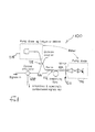
- the amplifiers 100 and 200 shown in Figures 1 and 2 are examples of amplifiers in which a spatial, or periodic, intensity pattern is set up in the gain medium to provide for automatic spectral gain compensation.
- the amplifier 100 has a gain medium comprising an erbium doped amplifying fibre 112 pumped by a pump source 114 or 116 at 1480 or 980nm for amplifying signal light of different wavelengths throughout a spectral window of at least 20nm and preferably about 30nm located at about 1550nm.
- Pump light for the pump source 114 is supplied to the erbium doped fibre 112 via a dichroic coupler 118 together with signal light.
- pump light from the pump source 116 is supplied to the fibre 112 via a dichroic end reflector 120 which is provided at the end 124 of the fibre 112, which is opposite the end 126 into which the signal light is supplied, for reflecting the signal light and allowing passage of the pump light.
- Astanding wave pattern is set up by interference of the forward and reflected signal light in the amplifier fibre 112. Signal light at different wavelengths will set up standing wave patterns of different periods. Thus each signal preferentially decreases it own gain with increasing signal level.
- the signal is coupled in and out via an optical circulator 128.
- both pump sources 14 and 16 may be provided or only one of them, but if pump source 116 is omitted the dichroic reflector 120 is still required.
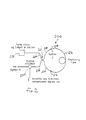
- the amplifier 200 comprises an erbium doped amplifying fibre 212 placed in a sagnac loop.
- the ends 214, 216 of the fibre 212 are spliced to the ends of two output fibre tails 218, 220 of a coupler 222 which has two input fibre tails 224, 226.
- Input fibre tail 224 receives pump light from a pump source 228 of, for example, 1480 or 980nm, which is supplied via the output fibre tail 220 of the coupler 222 to the amplifying fibre 212.
- Signal light at different wavelengths throughout a spectral window of at least 20nm and preferably about 30nm located at about 1550nm is received from an optical circulator 230 by input fibre tail 226, split into two by the coupler 222 and supplied via the two output fibre tails 218, 220 to the amplifying fibre 212.
- a standing wave pattern is set up by interference of the signal light travelling from end 214 to end 216 of the fibre 212 and the signal light travelling from end 216 to end 214 of the fibre 212 and as discussed above in connection with the arrangement of Figure 1 each signal preferentially decreases its own gain with increasing signal level.
- the amplified signal light is coupled together again by the coupler 222 and directed via tail 226 to the optical circulator 230.
- the amplifiers 300 and 400 shown in Figures 3 and 7 are examples of amplifiers in which signals of different wavelengths are spatially separated to provide for or allow automatic spectral gain compensation.
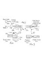
- the amplifier 300 has a gain medium which comprises an amplifying optical fibre 312 having two cores 314, 316 at least one of which is active by being doped with erbium.
- Pump light for example at 1480 or 980nm from a pump source 318 is supplied to end 320 of the fibre 312 via a dichroic coupler 322 which also supplies signal light at different wavelengths throughout a spectral window of at least 20nm and preferably about 30nm located at about 1550nm to the fibre end 320.
- the pump and signal light may be launched into one (as better illustrated in Figure 4) or each of the cores 314, 316 via a fusion splice 324 between the fibre 312 and a single mode output fibre tail 326 of the coupler.
- the cores are arranged such that optical power at each wavelength couples sinusoidally between the two cores down the fibre with a typical coupling length of about 1cm.
- the coupling length for this process is a function of the optical wavelength and thus the different signal wavelengths preferentially interact with different erbium ions. As a result automatic spectral gain compensation is obtained.
- the two cores of the fibre 312 could be identical, to provide approximately 100% coupling at all wavelengths.
- the propagation constants might only be matched at the signal wavelengths such that there is low coupling at the pump wavelength but approximately 100% coupling at the signal wavelengths.
- the coupling length would be designed to be in the range 100 ⁇ m to 1m and the length of the amplifying fibre 312 would be in the range 10cm to 100km.
- the power is split arbitrarily between the two cores 314, 316 since the total fibre length cannot be an exact integer number of coupling lengths for all possible signal wavelengths.
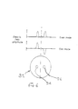
- the distribution of power between the two cores of a twincore fibre is a result of the superposition of an even and odd mode which have equal power irrespective of wavelength as shown in Figure 6. These two modes travel at different velocities and thus result in the observed coupling of power between the two cores.
- For small core to core separations tapering the twincore fibre at the output end to approximately one half its original diameter (as indicated in Figure 5) results in the cutoff of the odd (second) mode.
- the even mode which then approximates well to a Guassian can be coupled without significant loss into a single-mode fibre.
- An advantage of this technique is that the power in the even mode is independent of the precise amplifier length.
- the amplifier 400 shown in Figure 7 includes an amplifying fibre 412 which comprises an erbium doped fibre.
- Pump light at 1480 or 980nm is supplied from a pump source 414 via a dichroic coupler 416 to an input end 418 of the amplifying fibre 412.
- Signals of different wavelengths throughout a spectral window of at least 20nm and preferably about 30nm located at about 1550nm are also supplied to the amplifying fibre input end 418.
- the amplified signal lights at the different wavelengths from the output end 420 of the amplifying fibre are spatially separated by first optical means 422 comprising collimating means 424 for collimating the amplified output signal lights and a grating 426 or prism.
- the spatially separated signal lights are then passed through a means 428 for modifying their amplification such that the output levels of the signals are more equal than the levels of the signals inputted to the amplifying fibre.
- the modifying means may comprise a non-linear intensity dependent absorbing or amplifying device such as an array of self-electro-optic devices (seeds) or a suitable semiconductor material.
- the modified spatially separated signals are then recombined downstream of the modifying means 428 by a second optical means 430 comprising collimating means and a grating or prism and fed back into a transmission fibre 432 at the output 434 of the amplifier.
- the modifying means 428 performs spectral reshaping since it acts independently on the spatially separated signals.
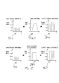
- Figure 8 shows in the upper portion how an input signal spectrum 500 is amplified to an output signal spectrum 510 using an amplifiersuch as disclosed in GB-A-2246234 having a gain spectrum 520.
- input signals at different wavelengths represented to vertical lines throughout a spectral window are amplified in accordance with the gain spectrum 520 to provide output signals and as the gain spectrum is substantially flat across the spectral window the output levels of the signals are markedly less equal than the input levels thereof.
- the lower portion of Figure 8 shows how an identical input signal spectrum 550 to spectrum 500 is typically amplified to an output signal spectrum 560 when using an amplifier embodying the present invention.
- the gain spectrum for the input signal spectrum 550 is illustrated at 570 and indicates the presence of automatic spectral gain compensation.
- the amplification of the input signals at different wavelengths represented by vertical lines is modified such that the output levels of the signals are more equal than the input levels thereof.
- the levels of the input signals are substantially equal the levels of the output signals will be less equal using either an amplifier as disclosed in GB-A-2246234 or an amplifier in accordance with the present invention having automatic spectral gain compensation, because of the ripple on the substantially flat portion of the gain spectra.
- signals whose levels are originally substantially equal will become successively less equal as they pass through the amplifiers.
- the amplifiers have automatic spectral gain compensation in accordance with the invention, once the levels of the signals differ by more than a predetermined amount an amplifier having such signals inputted will modify the amplification of those signals such that the output levels are more equal than the input levels. Eventually the output levels stabilise such that they are substantially as equal as the input levels.
Landscapes
- Physics & Mathematics (AREA)
- Electromagnetism (AREA)
- Engineering & Computer Science (AREA)
- Plasma & Fusion (AREA)
- Optics & Photonics (AREA)
- Lasers (AREA)
- Semiconductor Lasers (AREA)
- Optical Communication System (AREA)
Applications Claiming Priority (2)
| Application Number | Priority Date | Filing Date | Title |
|---|---|---|---|
| GB9206304 | 1992-03-23 | ||
| GB9206304A GB2265751B (en) | 1992-03-23 | 1992-03-23 | Optical amplifier with automatic self adjusting gain spectrum |
Publications (2)
| Publication Number | Publication Date |
|---|---|
| EP0566236A1 true EP0566236A1 (fr) | 1993-10-20 |
| EP0566236B1 EP0566236B1 (fr) | 1998-05-20 |
Family
ID=10712659
Family Applications (1)
| Application Number | Title | Priority Date | Filing Date |
|---|---|---|---|
| EP93301692A Expired - Lifetime EP0566236B1 (fr) | 1992-03-23 | 1993-03-05 | Amplicateur optique avec spectre de gain automatiquement auto-ajustable |
Country Status (6)
| Country | Link |
|---|---|
| US (1) | US5526175A (fr) |
| EP (1) | EP0566236B1 (fr) |
| CA (1) | CA2092146C (fr) |
| DE (1) | DE69318618T2 (fr) |
| ES (1) | ES2117098T3 (fr) |
| GB (1) | GB2265751B (fr) |
Cited By (9)
| Publication number | Priority date | Publication date | Assignee | Title |
|---|---|---|---|---|
| DE4331204A1 (de) * | 1992-09-14 | 1994-03-17 | Ando Electric | Optischer Pulsgenerator |
| WO1995032451A1 (fr) * | 1994-05-19 | 1995-11-30 | University Of Southampton | Dispositifs optiques |
| EP0685946A1 (fr) * | 1994-06-02 | 1995-12-06 | Nortel Networks Corporation | Amplificateur à guide d'ondes optique |
| EP0704945A1 (fr) * | 1994-09-29 | 1996-04-03 | Alcatel N.V. | Amplificateur optique régulé à circulateur optique |
| EP0734105A3 (fr) * | 1995-03-20 | 1998-04-15 | Fujitsu Limited | Amplificateur à fibre optique et module à fibre pour la compensation de la dispersion pour amplificateur à fibre optique |
| WO1998032198A1 (fr) * | 1997-01-15 | 1998-07-23 | Litton Systems, Inc. | Procede et dispositif convenant a un amplificateur de fibre optique |
| US5838487A (en) * | 1995-08-05 | 1998-11-17 | Samsung Electronics Co., Ltd. | Optical amplifiers |
| US6337763B1 (en) | 1999-01-25 | 2002-01-08 | Corning Incorporated | Distributed resonant ring fiber filter |
| EP3641079A1 (fr) * | 2013-03-01 | 2020-04-22 | Princeton Optronics, Inc. | Systèmes de gain à fibres optiques à pompage vcsel |
Families Citing this family (17)
| Publication number | Priority date | Publication date | Assignee | Title |
|---|---|---|---|---|
| GB2289978B (en) * | 1994-06-02 | 1997-11-26 | Northern Telecom Ltd | Optical waveguide amplifiers |
| EP0729207A3 (fr) * | 1995-02-24 | 1997-10-15 | At & T Corp | Amplificateur à fibres optiques comprenant un circulateur optique |
| JPH0918416A (ja) * | 1995-06-28 | 1997-01-17 | Hitachi Ltd | 光増幅器 |
| FR2737787B1 (fr) * | 1995-08-07 | 1997-10-31 | France Telecom | Amplificateur optique bidirectionnel pour systemes optiques a multiplexage en longueur d'onde |
| FR2737788B1 (fr) * | 1995-08-07 | 1998-12-04 | France Telecom | Amplificateur optique bidirectionnel pour systemes optiques a multiplexage en longueur d'onde |
| EP0883255A3 (fr) * | 1997-06-05 | 2002-01-09 | Nortel Networks Limited | Système de transmission WDM avec amplificateurs optiques |
| US6393167B1 (en) * | 1998-07-31 | 2002-05-21 | Monica K. Davis | Fast, environmentally-stable fiber switches using a Sagnac interferometer |
| US6204958B1 (en) * | 1998-10-08 | 2001-03-20 | Ciena Corporation | Optical amplifier having a substantially flat gain spectrum |
| DE19917751C2 (de) * | 1999-04-20 | 2001-05-31 | Nokia Networks Oy | Verfahren und Überwachungsvorrichtung zur Überwachung der Qualität der Datenübertragung über analoge Leitungen |
| US6377391B1 (en) * | 1999-08-02 | 2002-04-23 | The Board Of Trustees Of The Leland Stanford Junior University | Gain flattening with nonlinear Sagnac amplifiers |
| CA2394620A1 (fr) | 1999-12-16 | 2001-06-21 | Douglas E. Goforth | Fibres a gain optique |
| US6388803B1 (en) * | 2000-03-02 | 2002-05-14 | Agere Systems Guardian Corp. | Article comprising a broad band optical amplifier |
| US6552844B2 (en) | 2001-06-01 | 2003-04-22 | Agere Systems Guardian Corp. | Passively output flattened optical amplifier |
| KR100415548B1 (ko) * | 2001-08-16 | 2004-01-24 | 한국전자통신연구원 | 2단 장파장 대역 어븀첨가 광섬유 증폭 장치 |
| US6577789B1 (en) * | 2001-09-26 | 2003-06-10 | Onetta, Inc. | Double-pass optical amplifiers and optical network equipment |
| US9059799B2 (en) * | 2011-04-21 | 2015-06-16 | Futurewei Technologies, Inc. | Apparatus and method to calculate a noise figure of an optical amplifier for wavelength channels in a partial-fill scenario to account for channel loading |
| JP6064530B2 (ja) * | 2012-11-08 | 2017-01-25 | 住友電気工業株式会社 | 発光モジュール及び光トランシーバ |
Citations (2)
| Publication number | Priority date | Publication date | Assignee | Title |
|---|---|---|---|---|
| EP0450603A2 (fr) * | 1990-04-03 | 1991-10-09 | Canon Kabushiki Kaisha | Méthode et dispositif pour l'amplification de lumière avec un spectre d'amplification plat |
| US5067789A (en) * | 1991-02-14 | 1991-11-26 | Corning Incorporated | Fiber optic coupling filter and amplifier |
Family Cites Families (10)
| Publication number | Priority date | Publication date | Assignee | Title |
|---|---|---|---|---|
| US3868589A (en) * | 1972-10-10 | 1975-02-25 | Univ California | Thin film devices and lasers |
| US4358851A (en) * | 1980-02-28 | 1982-11-09 | Xerox Corporation | Fiber optic laser device and light emitter utilizing the device |
| US4405199A (en) * | 1981-02-11 | 1983-09-20 | Ogle James W | Method for enhancing signals transmitted over optical fibers |
| GB8629123D0 (en) * | 1986-12-05 | 1987-01-14 | Hussey C D | Fibre optic components |
| IT1237136B (it) * | 1989-10-30 | 1993-05-24 | Pirelli Cavi Spa | Amplificatore ottico a fibra attiva a larga banda di lunghezza d'onda di segnale. |
| IT1237970B (it) * | 1990-02-07 | 1993-06-19 | Pirelli Cavi Spa | Amplificatore ottico a fibra attiva,con porzioni a doppio nucleo,a larga banda di lunghezza d'onda di segnale |
| GB2246234A (en) * | 1990-05-21 | 1992-01-22 | Univ Southampton | Optical amplifier with shaped spectral gain |
| US5050949A (en) * | 1990-06-22 | 1991-09-24 | At&T Bell Laboratories | Multi-stage optical fiber amplifier |
| US5117303A (en) * | 1990-08-23 | 1992-05-26 | At&T Bell Laboratories | Method of operating concatenated optical amplifiers |
| US5148510A (en) * | 1990-11-28 | 1992-09-15 | Corning Incorporated | Optical fiber made of galliobismuthate glasses and optical devices using same |
-
1992
- 1992-03-23 GB GB9206304A patent/GB2265751B/en not_active Revoked
-
1993
- 1993-03-05 ES ES93301692T patent/ES2117098T3/es not_active Expired - Lifetime
- 1993-03-05 EP EP93301692A patent/EP0566236B1/fr not_active Expired - Lifetime
- 1993-03-05 DE DE69318618T patent/DE69318618T2/de not_active Expired - Lifetime
- 1993-03-22 CA CA002092146A patent/CA2092146C/fr not_active Expired - Lifetime
-
1994
- 1994-10-13 US US08/322,740 patent/US5526175A/en not_active Expired - Lifetime
Patent Citations (2)
| Publication number | Priority date | Publication date | Assignee | Title |
|---|---|---|---|---|
| EP0450603A2 (fr) * | 1990-04-03 | 1991-10-09 | Canon Kabushiki Kaisha | Méthode et dispositif pour l'amplification de lumière avec un spectre d'amplification plat |
| US5067789A (en) * | 1991-02-14 | 1991-11-26 | Corning Incorporated | Fiber optic coupling filter and amplifier |
Non-Patent Citations (5)
| Title |
|---|
| ELECTRONICS LETTERS. vol. 27, no. 23, 7 November 1991, STEVENAGE GB pages 2176 - 2177 H. SABERT ET AL. 'Reduction of spatial hole burning by singlephase modulator in linear Nd3+ fibre laser' * |
| ELECTRONICS LETTERS. vol. 27, no. 4, 14 February 1991, STEVENAGE GB pages 327 - 329 V. LAURIDSEN ET AL. 'Gain and noise performance of fibre amplifiers operating in new pump configurations' * |
| IEEE PHOTONICS TECHNOLOGY LETTERS vol. 4, no. 3, March 1992, NEW YORK US pages 269 - 271 S.F. SU ET AL. 'Gain equalization in multiwavelength lightwave systems using acoustooptic tunable filters' * |
| OPTICS LETTERS. vol. 16, no. 19, 1 October 1991, NEW YORK US pages 1499 - 1501 M. TACHIBANA ET AL. 'Gain cross saturation and spectral hole burning in wideband erbium-doped fiber amplifiers' * |
| PATENT ABSTRACTS OF JAPAN vol. 14, no. 414 (E-975)7 September 1990 & JP-A-02 159 085 ( FUJITSU ) * |
Cited By (21)
| Publication number | Priority date | Publication date | Assignee | Title |
|---|---|---|---|---|
| DE4331204A1 (de) * | 1992-09-14 | 1994-03-17 | Ando Electric | Optischer Pulsgenerator |
| US5930435A (en) * | 1994-05-19 | 1999-07-27 | University Of Southampton | Optical filter device |
| WO1995032451A1 (fr) * | 1994-05-19 | 1995-11-30 | University Of Southampton | Dispositifs optiques |
| EP1158350A1 (fr) * | 1994-05-19 | 2001-11-28 | University Of Southampton | Dispositifs optiques |
| EP1158351A1 (fr) * | 1994-05-19 | 2001-11-28 | University Of Southampton | Dispositfs optiques |
| EP0685946A1 (fr) * | 1994-06-02 | 1995-12-06 | Nortel Networks Corporation | Amplificateur à guide d'ondes optique |
| US5636054A (en) * | 1994-09-29 | 1997-06-03 | Alcatel N.V. | Regulated optical amplifier having an optical circulator |
| FR2725283A1 (fr) * | 1994-09-29 | 1996-04-05 | Alcatel Nv | Amplificateur optique regule a circulateur optique |
| EP0704945A1 (fr) * | 1994-09-29 | 1996-04-03 | Alcatel N.V. | Amplificateur optique régulé à circulateur optique |
| US6342965B1 (en) | 1995-03-20 | 2002-01-29 | Fujitsu Limited | Optical fiber amplifier and dispersion compensating fiber module for optical fiber amplifier |
| EP0734105A3 (fr) * | 1995-03-20 | 1998-04-15 | Fujitsu Limited | Amplificateur à fibre optique et module à fibre pour la compensation de la dispersion pour amplificateur à fibre optique |
| US6462862B2 (en) | 1995-03-20 | 2002-10-08 | Fujitsu Limited | Optical fiber amplifier and dispersion compensating fiber module for optical fiber amplifier |
| US6747788B2 (en) | 1995-03-20 | 2004-06-08 | Fujitsu Limited | Optical fiber amplifier and dispersion compensating fiber module for optical fiber amplifier |
| US6975447B2 (en) | 1995-03-20 | 2005-12-13 | Fujitsu Limited | Optical fiber amplifier and dispersion compensating fiber module for optical fiber amplifier |
| US7391562B2 (en) | 1995-03-20 | 2008-06-24 | Fujitsu Limited | Optical fiber amplifier and dispersion compensating fiber module for optical fiber amplifier |
| US7466477B2 (en) | 1995-03-20 | 2008-12-16 | Fujitsu Limited | Optical fiber amplifier and dispersion compensating fiber module for optical fiber amplifier |
| US5838487A (en) * | 1995-08-05 | 1998-11-17 | Samsung Electronics Co., Ltd. | Optical amplifiers |
| WO1998032198A1 (fr) * | 1997-01-15 | 1998-07-23 | Litton Systems, Inc. | Procede et dispositif convenant a un amplificateur de fibre optique |
| US6337763B1 (en) | 1999-01-25 | 2002-01-08 | Corning Incorporated | Distributed resonant ring fiber filter |
| US6429963B1 (en) | 1999-01-25 | 2002-08-06 | Corning Incorporated | Distributed resonant ring fiber filter |
| EP3641079A1 (fr) * | 2013-03-01 | 2020-04-22 | Princeton Optronics, Inc. | Systèmes de gain à fibres optiques à pompage vcsel |
Also Published As
| Publication number | Publication date |
|---|---|
| GB2265751B (en) | 1995-12-20 |
| US5526175A (en) | 1996-06-11 |
| CA2092146A1 (fr) | 1993-09-24 |
| GB9206304D0 (en) | 1992-05-06 |
| GB2265751A (en) | 1993-10-06 |
| ES2117098T3 (es) | 1998-08-01 |
| CA2092146C (fr) | 2001-02-13 |
| EP0566236B1 (fr) | 1998-05-20 |
| DE69318618T2 (de) | 1998-11-26 |
| DE69318618D1 (de) | 1998-06-25 |
Similar Documents
| Publication | Publication Date | Title |
|---|---|---|
| CA2092146C (fr) | Amplificateur optique a reglage automatique du gain | |
| US6876489B2 (en) | All band amplifier | |
| US6954303B2 (en) | Multi-stage optical amplifier and broadband communication system | |
| US6178038B1 (en) | Optical amplifier having an improved noise figure | |
| EP0938172B1 (fr) | Appareil comprenant un laser Raman à fibre en cascade amélioré | |
| US6603594B2 (en) | Multi-stage optical amplifier and broadband communication system | |
| US5978130A (en) | Dual-band fiber optic amplification system using a single pump source | |
| JP2734209B2 (ja) | 光ファイバ増幅器 | |
| US20030035202A1 (en) | Active gain equalization | |
| US6943936B2 (en) | Co-propagating Raman amplifiers | |
| EP0695050A1 (fr) | Système de télécommunication amplifié pour transmission à multiplexage en longueurs d'ondes avec égalisation de puissance de sortie | |
| EP1030414B1 (fr) | Article comprenant un amplificateur à fibre optique en bande L | |
| US6924926B2 (en) | Laser diode pump sources | |
| KR100649903B1 (ko) | 광통신 시스템 및 이에 사용되는 광 증폭 장치, 광 증폭유닛 및 광 커플러 | |
| Talam et al. | EDFA gain flattening using fiber Bragg gratings employing different host materials | |
| JP3129368B2 (ja) | 光信号伝送方法および中継増幅器 | |
| US6738180B2 (en) | Optical transmission system | |
| EP0964486A2 (fr) | Amplificateur à fibre optique | |
| JP2870870B2 (ja) | 光ファイバ増幅方法および光ファイバ増幅器 | |
| JPH1146167A (ja) | 光中継器 | |
| KR100194960B1 (ko) | 광 증폭기 | |
| JP4568247B2 (ja) | 光増幅モジュール及びそれを含む光増幅器 | |
| US20040090664A1 (en) | Integration of gain equalization filter in a gain medium | |
| KR0168913B1 (ko) | 다채널 광원 전송을 위한 광 섬유 증폭기 | |
| JP2827335B2 (ja) | 光ファイバ増幅器 |
Legal Events
| Date | Code | Title | Description |
|---|---|---|---|
| PUAI | Public reference made under article 153(3) epc to a published international application that has entered the european phase |
Free format text: ORIGINAL CODE: 0009012 |
|
| AK | Designated contracting states |
Kind code of ref document: A1 Designated state(s): DE ES FR GB IT |
|
| 17P | Request for examination filed |
Effective date: 19940418 |
|
| 17Q | First examination report despatched |
Effective date: 19950327 |
|
| GRAG | Despatch of communication of intention to grant |
Free format text: ORIGINAL CODE: EPIDOS AGRA |
|
| GRAG | Despatch of communication of intention to grant |
Free format text: ORIGINAL CODE: EPIDOS AGRA |
|
| GRAH | Despatch of communication of intention to grant a patent |
Free format text: ORIGINAL CODE: EPIDOS IGRA |
|
| GRAH | Despatch of communication of intention to grant a patent |
Free format text: ORIGINAL CODE: EPIDOS IGRA |
|
| GRAA | (expected) grant |
Free format text: ORIGINAL CODE: 0009210 |
|
| AK | Designated contracting states |
Kind code of ref document: B1 Designated state(s): DE ES FR GB IT |
|
| REF | Corresponds to: |
Ref document number: 69318618 Country of ref document: DE Date of ref document: 19980625 |
|
| ET | Fr: translation filed | ||
| REG | Reference to a national code |
Ref country code: ES Ref legal event code: FG2A Ref document number: 2117098 Country of ref document: ES Kind code of ref document: T3 |
|
| ITF | It: translation for a ep patent filed | ||
| PLBE | No opposition filed within time limit |
Free format text: ORIGINAL CODE: 0009261 |
|
| STAA | Information on the status of an ep patent application or granted ep patent |
Free format text: STATUS: NO OPPOSITION FILED WITHIN TIME LIMIT |
|
| 26N | No opposition filed | ||
| REG | Reference to a national code |
Ref country code: GB Ref legal event code: IF02 |
|
| PGFP | Annual fee paid to national office [announced via postgrant information from national office to epo] |
Ref country code: FR Payment date: 20120406 Year of fee payment: 20 |
|
| PGFP | Annual fee paid to national office [announced via postgrant information from national office to epo] |
Ref country code: IT Payment date: 20120327 Year of fee payment: 20 Ref country code: GB Payment date: 20120326 Year of fee payment: 20 |
|
| PGFP | Annual fee paid to national office [announced via postgrant information from national office to epo] |
Ref country code: DE Payment date: 20120328 Year of fee payment: 20 |
|
| REG | Reference to a national code |
Ref country code: DE Ref legal event code: R071 Ref document number: 69318618 Country of ref document: DE |
|
| REG | Reference to a national code |
Ref country code: GB Ref legal event code: PE20 Expiry date: 20130304 |
|
| PG25 | Lapsed in a contracting state [announced via postgrant information from national office to epo] |
Ref country code: GB Free format text: LAPSE BECAUSE OF EXPIRATION OF PROTECTION Effective date: 20130304 Ref country code: DE Free format text: LAPSE BECAUSE OF EXPIRATION OF PROTECTION Effective date: 20130306 |
|
| PGFP | Annual fee paid to national office [announced via postgrant information from national office to epo] |
Ref country code: ES Payment date: 20120326 Year of fee payment: 20 |
|
| REG | Reference to a national code |
Ref country code: ES Ref legal event code: FD2A Effective date: 20130718 |
|
| PG25 | Lapsed in a contracting state [announced via postgrant information from national office to epo] |
Ref country code: ES Free format text: LAPSE BECAUSE OF EXPIRATION OF PROTECTION Effective date: 20130306 |