EP0566280A2 - Méthode pour réunir des fibres optiques - Google Patents
Méthode pour réunir des fibres optiques Download PDFInfo
- Publication number
- EP0566280A2 EP0566280A2 EP93302563A EP93302563A EP0566280A2 EP 0566280 A2 EP0566280 A2 EP 0566280A2 EP 93302563 A EP93302563 A EP 93302563A EP 93302563 A EP93302563 A EP 93302563A EP 0566280 A2 EP0566280 A2 EP 0566280A2
- Authority
- EP
- European Patent Office
- Prior art keywords
- tubular member
- optical fibers
- reception space
- uniting
- memorized shape
- Prior art date
- Legal status (The legal status is an assumption and is not a legal conclusion. Google has not performed a legal analysis and makes no representation as to the accuracy of the status listed.)
- Granted
Links
Images





Classifications
-
- G—PHYSICS
- G02—OPTICS
- G02B—OPTICAL ELEMENTS, SYSTEMS OR APPARATUS
- G02B6/00—Light guides; Structural details of arrangements comprising light guides and other optical elements, e.g. couplings
- G02B6/24—Coupling light guides
- G02B6/36—Mechanical coupling means
- G02B6/40—Mechanical coupling means having fibre bundle mating means
- G02B6/403—Mechanical coupling means having fibre bundle mating means of the ferrule type, connecting a pair of ferrules
-
- A—HUMAN NECESSITIES
- A61—MEDICAL OR VETERINARY SCIENCE; HYGIENE
- A61B—DIAGNOSIS; SURGERY; IDENTIFICATION
- A61B1/00—Instruments for performing medical examinations of the interior of cavities or tubes of the body by visual or photographical inspection, e.g. endoscopes; Illuminating arrangements therefor
- A61B1/06—Instruments for performing medical examinations of the interior of cavities or tubes of the body by visual or photographical inspection, e.g. endoscopes; Illuminating arrangements therefor with illuminating arrangements
- A61B1/07—Instruments for performing medical examinations of the interior of cavities or tubes of the body by visual or photographical inspection, e.g. endoscopes; Illuminating arrangements therefor with illuminating arrangements using light-conductive means, e.g. optical fibres
-
- G—PHYSICS
- G02—OPTICS
- G02B—OPTICAL ELEMENTS, SYSTEMS OR APPARATUS
- G02B6/00—Light guides; Structural details of arrangements comprising light guides and other optical elements, e.g. couplings
- G02B6/04—Light guides; Structural details of arrangements comprising light guides and other optical elements, e.g. couplings formed by bundles of fibres
-
- G—PHYSICS
- G02—OPTICS
- G02B—OPTICAL ELEMENTS, SYSTEMS OR APPARATUS
- G02B6/00—Light guides; Structural details of arrangements comprising light guides and other optical elements, e.g. couplings
- G02B6/24—Coupling light guides
- G02B6/36—Mechanical coupling means
- G02B6/40—Mechanical coupling means having fibre bundle mating means
- G02B6/406—Mechanical coupling means having fibre bundle mating means of the ferrule type, connecting a plurality of pairs of ferrules
-
- Y—GENERAL TAGGING OF NEW TECHNOLOGICAL DEVELOPMENTS; GENERAL TAGGING OF CROSS-SECTIONAL TECHNOLOGIES SPANNING OVER SEVERAL SECTIONS OF THE IPC; TECHNICAL SUBJECTS COVERED BY FORMER USPC CROSS-REFERENCE ART COLLECTIONS [XRACs] AND DIGESTS
- Y10—TECHNICAL SUBJECTS COVERED BY FORMER USPC
- Y10T—TECHNICAL SUBJECTS COVERED BY FORMER US CLASSIFICATION
- Y10T29/00—Metal working
- Y10T29/49—Method of mechanical manufacture
- Y10T29/49826—Assembling or joining
- Y10T29/49863—Assembling or joining with prestressing of part
- Y10T29/49865—Assembling or joining with prestressing of part by temperature differential [e.g., shrink fit]
-
- Y—GENERAL TAGGING OF NEW TECHNOLOGICAL DEVELOPMENTS; GENERAL TAGGING OF CROSS-SECTIONAL TECHNOLOGIES SPANNING OVER SEVERAL SECTIONS OF THE IPC; TECHNICAL SUBJECTS COVERED BY FORMER USPC CROSS-REFERENCE ART COLLECTIONS [XRACs] AND DIGESTS
- Y10—TECHNICAL SUBJECTS COVERED BY FORMER USPC
- Y10T—TECHNICAL SUBJECTS COVERED BY FORMER US CLASSIFICATION
- Y10T29/00—Metal working
- Y10T29/49—Method of mechanical manufacture
- Y10T29/49826—Assembling or joining
- Y10T29/49906—Metal deforming with nonmetallic bonding
-
- Y—GENERAL TAGGING OF NEW TECHNOLOGICAL DEVELOPMENTS; GENERAL TAGGING OF CROSS-SECTIONAL TECHNOLOGIES SPANNING OVER SEVERAL SECTIONS OF THE IPC; TECHNICAL SUBJECTS COVERED BY FORMER USPC CROSS-REFERENCE ART COLLECTIONS [XRACs] AND DIGESTS
- Y10—TECHNICAL SUBJECTS COVERED BY FORMER USPC
- Y10T—TECHNICAL SUBJECTS COVERED BY FORMER US CLASSIFICATION
- Y10T29/00—Metal working
- Y10T29/49—Method of mechanical manufacture
- Y10T29/49826—Assembling or joining
- Y10T29/49908—Joining by deforming
- Y10T29/49925—Inward deformation of aperture or hollow body wall
- Y10T29/49927—Hollow body is axially joined cup or tube
Definitions
- This invention relates to a method of uniting a number of optical fibers into a bundle.
- An optical fiber bundle has been widely used for transmitting illumination light in an endoscope.
- the optical fiber bundle is obtained by uniting or joining at least opposites ends of a number of optical fibers.
- tubular members have conventionally been used for this uniting operation. More specifically, the end portions of a number of optical fibers to which an adhesive has been applied are inserted into the tubular members, and the optical fibers are united together upon solidification of the adhesive. It is preferred that as many optical fibers as possible be inserted into the tubular member so as to increase the density of filling of the optical fibers. In the above method, however, when trying to insert as many optical fibers as possible into the tubular member, the optical fibers are rubbed by the inner surface of the tubular member, and are damaged. Therefore, to increase the density of filling of the optical fibers has been limited.
- Japanese Laid-Open Utility Model Application No. 59-43903 discloses a method of uniting optical fibers together, in which a number of optical fibers are first inserted into a tubular member of a circular cross-section, and then a wedge member is inserted into the tubular member, thereby increasing the density of filling of the optical fibers.
- the wedge member rubs the optical fibers, and therefore may damage them.
- optical fibers in a bent condition are united together.
- Japanese Laid-Open Patent Application No. 59-34239 shows in Fig. 5 a front end structure of an endoscope of a side-viewing type. End portions of optical fibers are bent generally right-angularly or perpendicularly, and in this condition they are united together by a uniting member.
- this uniting member is composed of two halves, and a pair of curved grooves are formed respectively in opposed surfaces of the two halves. The optical fibers are received in these grooves, and the two halves are connected together, with the two grooves mated together, thereby uniting the optical fibers.
- the density of filling of the optical fiber is low, and the uniting operation is quite cumbersome.
- This joint has a tubular shape, and is made of a shape memory alloy. Opposed ends of the two pipes are inserted respectively into the opposite end portions of the joint, and then heat is applied to the joint to return it to its memorized configuration, that is, a smaller diameter, thereby connecting the two pipes together.
- a method of uniting a number of optical fibers comprising the steps of:
- a method of uniting a number of optical fibers comprising the steps of:
- a tubular member 10 is prepared.
- This tubular member 10 is made of a shape memory alloy.
- the tubular member 10 is processed with respect to its memory at a temperature higher than an ordinary temperature (room temperature), and its memorized shape is a cylinder having an inner diameter d1, as shown in Figs. 3 and 4.
- the tubular member 10 is expanded in diameter at the ordinary temperature into a cylinder having an inner diameter d2 (d2 > d1), as shown in Figs. 1 and 2.
- the internal space or interior of the tubular member 10 serves as a reception space 11.
- the cross-sectional area of the reception space 11 is uniform throughout the length of the tubular member 10.
- a through hole 12 is formed through the peripheral wall of the tubular member 10.
- a maximum number for example, several thousands to several tens of thousands
- optical fibers 20 which can be inserted into the tubular member 10, having the inner diameter d2, without damage.
- One ends of these optical fibers 20 are disposed generally in a common plane, and in this condition an adhesive is applied to almost all of the optical fibers 20 over a predetermined distance (indicated by L in Fig. 2) from the one ends thereof.
- a number of optical fibers 20 mentioned above are inserted into the reception space 11 of the tubular member 10, and one ends of the optical fibers 20 are projected from one end of the tubular member 10. Since the diameter of the tubular member 10 is large, the optical fibers 20 can be easily inserted into the tubular member 10 without damage.
- the tubular member 10 is disposed on those portions of the optical fibers 20 to which the adhesive has been applied.
- the tubular member 10 is heated to be returned to its memorized shape, that is, into the cylindrical shape having the inner diameter d1.
- the optical fibers 20 are united together by the tubular member 10.
- the inner diameter d1 of the tubular member 10 is small, the number of optical fibers 20 to be united together can be increased, so that the density of filling of the optical fibers 20 can be increased.
- the adhesive is cured or set by the above heating.
- the cured adhesive prevents the optical fibers 20 from being withdrawn from the tubular member 10 after the optical fibers 20 are united together.
- the adhesive fills in gaps between the optical fibers 20 to thereby prevent the intrusion of water.
- the tubular member 10 When the tubular member 10 is reduced or contracted in diameter by heating, the adhesive leaks from the through hole 12 in the tubular member 10. Therefore, the amount of flow of the adhesive along the optical fibers 20 can be reduced. As a result, straight portions of the optical fibers 20 which are unable to be bent after the curing of the adhesive can be shortened.
- the end portions of the united optical fibers 20 projected from the end of the tubular member 10 are cut off, so that the cut ends of the optical fibers 20 lie substantially flush with the end of the tubular member 10. Then, the end faces of the optical fibers 20 are polished.
- the other ends of the optical fibers 20 are united together by the use of another tubular member 10' similar to the tubular member 10 in a manner described above.
- An optical fiber bundle 25, obtained by uniting both ends of the optical fibers by the respective tubular members 10 and 10', is incorporated, for example, into an endoscope 50 (Fig. 5) for transmitting illumination light.
- the endoscope 50 comprises a body 51, a flexible insertion portion 52 extending from the body 51, a bending portion 53 extending from a front end of the insertion portion 52, a rigid tip member 54 provided at a front end of the bending portion 53, a light guide cable 55 extending from the body 51, and a connector 56 mounted on a distal end of the light guide cable 55.
- a manipulation member 57 is mounted on the body 51, and by operating this manipulation member 57, the bending portion 53 is bent in a remotely-controlled manner.
- An ocular portion 58 is further provided on the body 51.
- one end portion of the optical fiber bundle 25 inserted into the connector 56 of a tubular shape, and is fixed to this connector 56 by a screw (not shown) which is threaded through the peripheral wall of the connector 56, and is firmly held at its distal end against the outer peripheral surface of the tubular member 10.
- the optical fiber bundle 25 passes sequentially through the light guide cable 55, the body 51, the insertion portion 52 and the bending portion 53, and is inserted into and fixed to the tip member 54 at the other end portion thereof, as shown in Fig. 7. More specifically, the tubular member 10' of the optical fiber bundle 25 is inserted into and fixed to a retainer tube 26.
- a flat pane 27 of glass, serving as an illumination window, is fitted in the front end of the retainer tube 26.
- the retainer tube 26 is fitted in and fixed to a through hole 54a formed through the tip member 54.
- the image transmission optical system 30 shown in Fig. 7 is provided between the ocular portion 58 and the tip member 54.
- the image transmission optical system 30 comprises an optical fiber bundle 31.
- the optical fiber bundle 31 comprises a number of optical fibers 32 united at their opposite ends by tubular members 33.
- One end portion of the optical fiber bundle 31, as well as a flat pane 37 of glass (which serves as an inspection window) and an objective lens 38, is fitted in and fixed to a retainer tube 36.
- This retainer tube 36 is inserted into and fixed to a through hole 54b of the tip member 54.
- the other end portion of the optical fiber bundle 31 is fixed, together with an ocular lens, to the ocular portion 58.
- the connector 56 of the endoscope 50 is connected to a light source device 60.
- the light source device 60 comprises a concave mirror 61 within a housing, and a lamp 62 which serves as a light source and mounted on the concave mirror 61. Illumination light from the lamp 62 is reflected by the concave mirror 61 to converge, and is incident on one end faces of the optical fibers 20 supported by the connector 56. This incident light passes through the optical fibers 20, and is applied to a body cavity via the illumination window 27. An image of an inner wall of the body cavity can be observed from the ocular portion 58 via the image transmission optical system 30.
- the connector 56 since the density of filling of the optical fibers 20 in the tubular member 10 is high, the connector 56 can efficiently receive the illumination light from the lamp 62. Also, in the tip member 54, since the density of filling of the optical fibers 20 in the tubular member 10' is high, a large amount of light can be applied from the tubular member 10' having a relatively small transverse cross-sectional area.
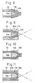
- a tubular member 10A is uniform in thickness throughout the length thereof, and an inner diameter of the tubular member 10A, as well as its outer diameter, is decreasing progressively toward one end of the tubular member 10A.
- a reception space 11A of the tubular member 10A has a circular transverse cross-section, and is decreasing progressively toward one end thereof.
- the tubular member 10A is made of a shape memory alloy, and is processed in such a manner that it is larger in diameter than its memorized shape.
- optical fibers 20 are inserted into the reception space 11A of the tubular member 10A, and then a core 15A of a conical shape is inserted into a bundle of optical fibers 20.
- the optical fibers are disposed between the outer peripheral surface of the core 15A and the inner peripheral surface of the tubular member 10A.
- the tubular member 10A is heated to be returned to its memorized shape having the smaller diameter, so that the optical fibers 20 are united together.
- the end portions of the optical fibers 20 projected from one end of the tubular member 10A is cut off, so that the cut ends of the optical fibers 20 lie substantially flush with the one end of the tubular member 10A.
- the end portions of the thus united optical fibers 20 are inserted into and fixed to a connector 56A of an endoscope.
- the end portions of the optical fibers 20 flare to the left in Fig. 9, and therefore the angle between illumination light, which is emitted from a light source to be incident on each optical fiber 20, and the optical fiber 20 is small, so that the optical fibers 20 can efficiently receive the illumination light.
- a tubular member 10B made of a shape memory alloy has a cylindrical outer peripheral surface.
- a reception space 11B of the tubular member 10B has a circular transverse cross-section, and is decreasing at its one end portion progressively toward one open end of the tubular member 10B.
- the tubular member 10B is processed in such a manner that this open end is larger in diameter than its memorized shape.
- a core 15B has a left end portion of a cylindrical shape, and a right end portion of a conical shape.
- optical fibers 20 are disposed between the tubular member 10B and the core 15B.
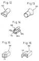
- Figs. 12 to 16 respectively show modified tubular members of a shape memory alloy in their respective memorized shapes, which tubular members are used for uniting optical fibers.
- the tubular member 10C of Fig. 12 has one end portion of a circular transverse cross-section, and the other end portion of an oval transverse cross-section.
- the tubular member 10D of Fig. 13 has a cylindrical shape at its one end portion, and is increasing in diameter toward the other end.
- Each of the tubular members 10C and 10D are processed in such a manner that it is larger in diameter than its memorized shape throughout the length thereof.
- a reception space 11E of the tubular member 10E has a generally C-shape.
- the tubular member 10E is processed in such a manner that the outer arcuate portion 10Ea is larger in diameter than its memorized shape.
- the tubular member 10F of Fig. 15, as well as the tubular member 10G of Fig. 16, has a generally rectangular cross-section. Each of these tubular members 10F and 10G is processed in such a manner that its reception space 11F, 11G is larger in cross-sectional area than that of the memorized shape.
- a coil 10H made of a shape memory alloy is used as a tubular member.
- the coil 10H is processed in such a manner that it is larger in diameter than its memorized shape.
- a number of optical fibers 20 are inserted into a reception space 11H of the tubular member 10H, and one end portions of the optical fibers 20 are projected from one end of the tubular member 10H.
- the tubular member 10H is heated to be returned to its memorized shape having the smaller diameter, thereby uniting the optical fibers 20 together.
- the end portions of the optical fibers 20 projected from the tubular member 10H are cut off, so that the cut ends of the optical fibers 20 lie substantially flush with the end of the tubular member 10.
- the end faces of the optical fibers 20 are polished.
- the optical fibers united by the above tubular members 10C to 10H are used for transmitting illumination light in an endoscope.
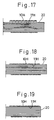
- a tubular member 10J used in this embodiment in its memorized shape, has a circular cross-section, and has an axis of an L-shape which is bent generally perpendicularly.
- the tubular member 10J is processed in such a manner that it is larger in diameter and is curved along its axis more gently than its memorized shape.
- One end portions of a number of optical fibers 20 are inserted into the tubular member 10J.
- the curvature or bending of the tubular member 10J in the axial direction is gentle, and besides the cross-sectional area of a reception space 11J is large, and therefore the insertion of the optical fibers 20 is easy.
- the tubular member 10J is heated to be returned to its memorized shape, so that the tubular member 10J is reduced in diameter and is brought into the perpendicularly-bent condition, thereby uniting the one end portions of the optical fibers 20.
- the end portions projected from the tubular member 10J are cut off.
- the other end portions of the optical fibers 20 are united together in the manner as described in any one of the above embodiments.
- one end portion of the thus obtained optical fiber bundle 25J is incorporated into a tip member 54J of the endoscope.
- the tip member 54J is composed of two halves having L-shaped grooves in their opposed surfaces, respectively. The two halves are joined together with the tubular member 10J fitted in the opposed L-shaped grooves, thereby attaching the optical fiber bundle 25J to the tip member 54J.
- the pair of grooves cooperate with each other to form a through hole 54Ja receiving the tubular member 10J.
- One end portion of an image transmission optical system 30 is also attached to the tip member 54J when the above two halves are joined together.
- a prism 39 is provided between an inspection window 37 and an objective lens 38.
- Figs. 22 and 23 show a method of uniting optical fibers intermediate opposite ends thereof.
- a tubular member 10K used in this embodiment in its memorized shape, has a circular cross-section, and has a generally S-shaped axis.
- the tubular member 10K is processed in such a manner that it is larger in diameter and is curved along its axis more gently than its memorized shape.
- a number of optical fibers 20 are inserted through the tubular member 10K. At this time, the curvature or bending of the tubular member 10K in the axial direction is gentle, and besides the cross-sectional area of a reception space 11K is large, and therefore the insertion of the optical fibers 20 is easy.
- the tubular member 10K is heated to be returned to its memorized shape, so that the tubular member 10K is reduced in diameter and is brought into the S-shaped, bent condition, thereby uniting the optical fibers 20 intermediate the opposite ends thereof.
- the opposite end portions of the optical fibers 20 are united in the manner as described above in any one of the above embodiments.
- An optical fiber bundle 25K obtained by thus uniting the optical fibers 20 is incorporated into an endoscope.
- An intermediate portion of the optical fiber bundle 25K is received within a body 51K of the endoscope.
- the body 51K includes a base portion 51Ka, and a hollow projection 51Kb projected from the base portion 51Ka.
- the above tubular member 10K is received in the base portion 51Ka and the projection 51Kb.
- the optical fiber bundle 25K extended from the projection 51Kb is covered by a light guide cable.
- the optical fiber bundle 25K is protected by the tubular member 10K, and therefore is prevented from being damaged by movable portions in the body 51K.
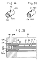
- the outer tubular member 10K1 is made of a shape memory alloy, and is processed in such a manner that it is larger in diameter than its memorized shape.
- the outer tubular member 10K1 has a through hole 12 for allowing the leakage of an adhesive.
- the inner tubular member 10K2 is received in the outer tubular member 10K2 to form a reception space 11K therebetween, and one end portions of optical fibers 20 are inserted into the reception space 11K.
- the front ends of the optical fibers 20 are spaced rearwardly from one ends of the tubular members 10K1 and 10K2.
- the outer tubular member 10K1 is heated to be returned to its memorized shape having the smaller diameter, thereby uniting the optical fibers 20.
- one end portion of an image transmission optical system 30 including an objective lens is inserted into and fixed to the inner tubular member 10K2, and an annular glass pane 27K serving as an illumination window is fitted between the front end portions of the tubular members 10K1 and 10K2.
- a tip assembly thus obtained is fitted in and fixed to a through hole 54Ka in a tip member 54K.
- the inner tubular member 10K2 of Fig. 24 may be replaced by an inner tubular member 10K2' of Fig. 26.
- the inner tubular member 10K2, 10K2' may be made of a shape memory alloy.
- the inner tubular member 10K2, 10K2' may be made of a shape memory alloy.
- the inner tubular member 10K2, 10K2' is processed in such a manner that it is smaller in diameter than its memorized shape, and when the inner tubular member is heated, it is returned to its memorized shape having the larger diameter, thereby reducing the cross-sectional area of the reception space 11K.
- the inner tubular member 10K2 may have an adhesive leakage through hole.
- the inner tubular member 10K2 may have an adhesive leakage through hole.
- a tubular member 40 and a partition plate 45 of a shape memory alloy there are used a tubular member 40 and a partition plate 45 of a shape memory alloy.
- the partition plate 45 in its memorized shape is flat, and has a width equal to the inner diameter of the tubular member 40.
- the partition plate 45 is processed in such a manner that it is curved into an arcuate transverse cross-section at an ordinary temperature.
- the curved partition plate 45 when received into the tubular member 40, divides an internal space of the tubular member 40 into two sections, that is, a pair of reception spaces 41 and 42.
- One end portions of optical fibers 20 is inserted into the lower reception space 41 of a larger volume.
- the end portions of the optical fibers 20 are first inserted into the tubular member 40, and then the partition plate 45 is inserted into the tubular member 40 in such a manner that the partition plate 45 rests on the optical fibers 20 during the insertion.
- the partition plate 45 is heated to be returned to its memorized shape, that is, the flat shape.
- the partition plate 45 is disposed on the center of the tubular member 40, and the cross-sectional area of the reception space 41 is reduced, thereby uniting the end portions of the optical fibers 20.
- the central portion of the partition plate 45 is prevented by a jig from upward movement when the partition plate 45 is to be heated.
- the cross-sectional area of the reception space may be reduced by returning the tubular member from a transverse circular cross-section to a memorized, transverse non-circular cross-section by application of heat.
- the cross-sectional area of the reception space may be reduced by returning the inner tubular member from a non-circular cross-section to a memorized, circular cross-section by application of heat.
- the united optical fibers may be used in the image transmission optical system of the endoscope.
- the united optical fibers may also be used in other devices than an endoscope.
Landscapes
- Physics & Mathematics (AREA)
- Optics & Photonics (AREA)
- General Physics & Mathematics (AREA)
- Health & Medical Sciences (AREA)
- Life Sciences & Earth Sciences (AREA)
- Surgery (AREA)
- Engineering & Computer Science (AREA)
- Medical Informatics (AREA)
- Radiology & Medical Imaging (AREA)
- Nuclear Medicine, Radiotherapy & Molecular Imaging (AREA)
- Biophysics (AREA)
- Biomedical Technology (AREA)
- Heart & Thoracic Surgery (AREA)
- Pathology (AREA)
- Molecular Biology (AREA)
- Animal Behavior & Ethology (AREA)
- General Health & Medical Sciences (AREA)
- Public Health (AREA)
- Veterinary Medicine (AREA)
- Endoscopes (AREA)
- Optical Fibers, Optical Fiber Cores, And Optical Fiber Bundles (AREA)
- Instruments For Viewing The Inside Of Hollow Bodies (AREA)
Applications Claiming Priority (3)
| Application Number | Priority Date | Filing Date | Title |
|---|---|---|---|
| JP12128592A JP3210404B2 (ja) | 1992-04-15 | 1992-04-15 | 光ファイバー用結束装置 |
| JP12128592 | 1992-04-15 | ||
| JP121285/92 | 1992-04-15 |
Publications (3)
| Publication Number | Publication Date |
|---|---|
| EP0566280A2 true EP0566280A2 (fr) | 1993-10-20 |
| EP0566280A3 EP0566280A3 (en) | 1994-08-17 |
| EP0566280B1 EP0566280B1 (fr) | 1999-06-30 |
Family
ID=14807476
Family Applications (1)
| Application Number | Title | Priority Date | Filing Date |
|---|---|---|---|
| EP93302563A Expired - Lifetime EP0566280B1 (fr) | 1992-04-15 | 1993-04-01 | Méthode pour réunir des fibres optiques |
Country Status (4)
| Country | Link |
|---|---|
| US (2) | US6101703A (fr) |
| EP (1) | EP0566280B1 (fr) |
| JP (1) | JP3210404B2 (fr) |
| DE (1) | DE69325477T2 (fr) |
Cited By (3)
| Publication number | Priority date | Publication date | Assignee | Title |
|---|---|---|---|---|
| WO1995031926A1 (fr) * | 1994-05-23 | 1995-11-30 | Sachdeva Rohit C I | Instrument pour procedures de type endoscopique |
| WO2002041037A3 (fr) * | 2000-11-16 | 2003-05-01 | Schott Glas | Procede de transfert d'un grand nombre d'extremites de fibres dans une position determinee |
| US6780175B1 (en) | 1996-02-23 | 2004-08-24 | Memory Medical Systems, Inc. | Medical instrument with slotted memory metal tube |
Families Citing this family (18)
| Publication number | Priority date | Publication date | Assignee | Title |
|---|---|---|---|---|
| JP3610157B2 (ja) * | 1996-04-03 | 2005-01-12 | オリンパス株式会社 | 内視鏡 |
| JP3710610B2 (ja) * | 1997-10-17 | 2005-10-26 | 株式会社フジクラ | ファイバスコープおよびその製造方法 |
| HU225935B1 (en) * | 2001-03-23 | 2008-01-28 | Phoenix Rubber Gumiipari Kft | Method for manufacturing outside armoured rubber hose |
| JP4183991B2 (ja) * | 2002-07-12 | 2008-11-19 | シーシーエス株式会社 | 光ファイバ保持装置、光ファイバ保持方法 |
| US7055235B2 (en) * | 2004-03-04 | 2006-06-06 | Chin Ju Liu | Sleeve for connector of optical fibers and method of manufacturing same |
| JP4916164B2 (ja) * | 2005-12-02 | 2012-04-11 | オリンパスメディカルシステムズ株式会社 | 内視鏡 |
| CN100392459C (zh) * | 2006-07-05 | 2008-06-04 | 仪和仪美(北京)科技有限公司 | 光纤插座及光纤插头 |
| EP2089747A4 (fr) * | 2006-12-08 | 2010-07-21 | Wallac Oy | Câble à fibre optique et son procédé de production |
| US8326103B2 (en) * | 2008-04-04 | 2012-12-04 | Baker Hughes Incorporated | Cable and method |
| DE102010056025A1 (de) | 2010-12-27 | 2012-06-28 | Olympus Winter & Ibe Gmbh | Endoskop mit einem Schaftrohr |
| DE102012200794A1 (de) | 2012-01-20 | 2013-07-25 | Karl Storz Gmbh & Co. Kg | Lichtleiter mit einem Bündel von lichtleitenden Fasern und ein Verfahren zur Biegung des Lichtleiters |
| US9946033B2 (en) * | 2013-08-07 | 2018-04-17 | Corning Optical Communications LLC | Fiber optic connector with adhesive management |
| DE102013110692A1 (de) * | 2013-09-27 | 2015-04-02 | Karl Storz Gmbh & Co. Kg | Herstellen eines Endoskops mit einer Lichtleiteinrichtung |
| DE102014111069A1 (de) * | 2014-08-04 | 2016-02-04 | Olympus Winter & Ibe Gmbh | Endoskop und Verfahren zur Montage eines Endoskops |
| DE102015203357A1 (de) | 2015-02-25 | 2016-08-25 | Olympus Winter & Ibe Gmbh | Optische Baueinheit eines Endoskops |
| JP6817920B2 (ja) * | 2017-10-24 | 2021-01-20 | 三菱電線工業株式会社 | 光ファイババンドル端末構造 |
| WO2020217351A1 (fr) * | 2019-04-24 | 2020-10-29 | オリンパス株式会社 | Dispositif d'imagerie d'endoscope et endoscope |
| WO2022159782A1 (fr) | 2021-01-22 | 2022-07-28 | Macleon, LLC | Câble à fibres optiques et système et procédé de distribution d'ultra-haute puissance à l'aide de celui-ci |
Family Cites Families (21)
| Publication number | Priority date | Publication date | Assignee | Title |
|---|---|---|---|---|
| US3579805A (en) * | 1968-07-05 | 1971-05-25 | Gen Electric | Method of forming interference fits by heat treatment |
| US3580775A (en) * | 1969-04-28 | 1971-05-25 | American Optical Corp | Method of making fiberscopes with trimmed tips |
| US3834008A (en) * | 1973-01-29 | 1974-09-10 | Uniroyal Inc | Method of joining two wire cords |
| US4198081A (en) * | 1973-10-29 | 1980-04-15 | Raychem Corporation | Heat recoverable metallic coupling |
| US3914015A (en) * | 1974-10-15 | 1975-10-21 | Itt | Fiber optic connector and assembly method |
| GB2025084B (en) * | 1978-06-19 | 1982-07-07 | Elliott Brothers London Ltd | Terminating optical fibres |
| GB2053766B (en) * | 1979-07-24 | 1983-01-06 | Fulmer Res Inst Ltd | Mounting connectors on elongate members |
| US4352542A (en) * | 1980-08-26 | 1982-10-05 | The United States Of America As Represented By The Secretary Of The Navy | Cable connector |
| JPS5934239A (ja) * | 1982-08-20 | 1984-02-24 | オリンパス光学工業株式会社 | 内視鏡 |
| JPS5943903A (ja) * | 1982-09-06 | 1984-03-12 | Mitsubishi Heavy Ind Ltd | 翼付根付近にクラツクを発生させる方法 |
| CA1214660A (fr) * | 1982-09-30 | 1986-12-02 | Koichiro Inomata | Dynamometre, et sa fabrication |
| ATE40011T1 (de) * | 1982-11-26 | 1989-01-15 | British Telecomm | Verbindungsstuecke. |
| JPS59121006A (ja) * | 1982-12-27 | 1984-07-12 | Omron Tateisi Electronics Co | 光学導体の実装構造 |
| GB2185923B (en) * | 1986-02-05 | 1989-12-20 | Fulton | Tube assemblies |
| US4743084A (en) * | 1986-05-14 | 1988-05-10 | Amp Incorporated | Optical fiber connector for field application |
| JPS6459304A (en) * | 1987-08-31 | 1989-03-07 | Showa Electric Wire & Cable Co | Connecting method for frp covered optical fiber cable |
| JPH01109310A (ja) * | 1987-10-23 | 1989-04-26 | Hitachi Ltd | 樹脂製光フアイバ接続管 |
| US4894906A (en) * | 1987-12-23 | 1990-01-23 | Nicolet Instrument Corporation | Superconductive joint for multifilament superconducting and method of forming |
| US4921323A (en) * | 1988-12-22 | 1990-05-01 | Kingston Technologies, L.P. | Memory polymer optical fiber splicer and methods |
| IT1231076B (it) * | 1989-09-28 | 1991-11-12 | Pirelli Cavi Spa | Procedimento per la realizzazione di gruppo di connessione separabile per fibre ottiche riunite a nastro e gruppo di connessione con esso realizzato. |
| US5231681A (en) * | 1990-12-14 | 1993-07-27 | Telefonaktiebolaget Lm Ericsson | Optical fibre cable for detecting a change in temperature |
-
1992
- 1992-04-15 JP JP12128592A patent/JP3210404B2/ja not_active Expired - Fee Related
-
1993
- 1993-04-01 DE DE69325477T patent/DE69325477T2/de not_active Expired - Fee Related
- 1993-04-01 EP EP93302563A patent/EP0566280B1/fr not_active Expired - Lifetime
- 1993-04-07 US US08/043,743 patent/US6101703A/en not_active Expired - Fee Related
-
2000
- 2000-05-10 US US09/568,042 patent/US6324742B1/en not_active Expired - Fee Related
Cited By (6)
| Publication number | Priority date | Publication date | Assignee | Title |
|---|---|---|---|---|
| WO1995031926A1 (fr) * | 1994-05-23 | 1995-11-30 | Sachdeva Rohit C I | Instrument pour procedures de type endoscopique |
| US5607435A (en) * | 1994-05-23 | 1997-03-04 | Memory Medical Systems, Inc. | Instrument for endoscopic-type procedures |
| EP1221296A2 (fr) | 1994-05-23 | 2002-07-10 | Rohit C. L. Sachdeva | Instrument endoscopique |
| US6780175B1 (en) | 1996-02-23 | 2004-08-24 | Memory Medical Systems, Inc. | Medical instrument with slotted memory metal tube |
| US7037321B2 (en) | 1996-02-23 | 2006-05-02 | Memory Medical Systems, Inc. | Medical device with slotted memory metal tube |
| WO2002041037A3 (fr) * | 2000-11-16 | 2003-05-01 | Schott Glas | Procede de transfert d'un grand nombre d'extremites de fibres dans une position determinee |
Also Published As
| Publication number | Publication date |
|---|---|
| DE69325477D1 (de) | 1999-08-05 |
| DE69325477T2 (de) | 2000-03-16 |
| EP0566280B1 (fr) | 1999-06-30 |
| JPH05297287A (ja) | 1993-11-12 |
| JP3210404B2 (ja) | 2001-09-17 |
| US6324742B1 (en) | 2001-12-04 |
| US6101703A (en) | 2000-08-15 |
| EP0566280A3 (en) | 1994-08-17 |
Similar Documents
| Publication | Publication Date | Title |
|---|---|---|
| US6101703A (en) | Method of uniting optical fibers | |
| US4294234A (en) | Endoscope | |
| US4183618A (en) | Couplings and terminals for optical waveguides | |
| US5680492A (en) | Singular fiber to bundle illumination with optical coupler | |
| US9989711B2 (en) | Fiber optic connector and fiber optic cable assembly with fiber optic cable anchored to boot of fiber optic connector | |
| JP2928101B2 (ja) | 光ファイバーコネクター | |
| US4687288A (en) | Fiber optic connector with temperature compensating mechanism | |
| US4684205A (en) | Fiber optic connector with compensating mechanism | |
| CN101515051B (zh) | 光纤用连接器 | |
| JP2002341185A (ja) | ファイバ位置決めコネクタを有する光ファイバモジュールアタッチメント | |
| JP2002541525A (ja) | 多重式導光コネクタ用の光ファイバ照明器アダプタ・アセンブリ | |
| US4844580A (en) | Fiber optic lens | |
| US5193135A (en) | Optical connector and endoscope with optical connector | |
| KR100713430B1 (ko) | 광커넥터 플러그, 그 제조방법 및 조립공구 | |
| CA1298504C (fr) | Raccord optique reconfigurable a tiges | |
| US6604867B2 (en) | Fiber optic connector | |
| US4183615A (en) | Couplings and terminals for optical waveguides | |
| US5018818A (en) | Field installable fiber optic connector | |
| CN105511020B (zh) | 光纤连接器及其组装方法 | |
| EP1286193A2 (fr) | Connecteur pour câble de fibres optiques et procédé de fabrication de ceux-ci | |
| KR100970853B1 (ko) | 광섬유 케이블 커넥터 시스템 | |
| JPH0335209A (ja) | 光導波管用コネクタ | |
| CN114847866B (zh) | 侧面oct成像微型光纤内窥镜探针及其制作方法 | |
| JP2001501325A (ja) | 高強度点光源をファイバ束に連結する方法 | |
| GB2127170A (en) | Fibre optic cables |
Legal Events
| Date | Code | Title | Description |
|---|---|---|---|
| PUAI | Public reference made under article 153(3) epc to a published international application that has entered the european phase |
Free format text: ORIGINAL CODE: 0009012 |
|
| AK | Designated contracting states |
Kind code of ref document: A2 Designated state(s): DE FR GB |
|
| PUAL | Search report despatched |
Free format text: ORIGINAL CODE: 0009013 |
|
| AK | Designated contracting states |
Kind code of ref document: A3 Designated state(s): DE FR GB |
|
| 17P | Request for examination filed |
Effective date: 19941004 |
|
| 17Q | First examination report despatched |
Effective date: 19970307 |
|
| GRAG | Despatch of communication of intention to grant |
Free format text: ORIGINAL CODE: EPIDOS AGRA |
|
| GRAG | Despatch of communication of intention to grant |
Free format text: ORIGINAL CODE: EPIDOS AGRA |
|
| GRAG | Despatch of communication of intention to grant |
Free format text: ORIGINAL CODE: EPIDOS AGRA |
|
| GRAH | Despatch of communication of intention to grant a patent |
Free format text: ORIGINAL CODE: EPIDOS IGRA |
|
| GRAH | Despatch of communication of intention to grant a patent |
Free format text: ORIGINAL CODE: EPIDOS IGRA |
|
| GRAA | (expected) grant |
Free format text: ORIGINAL CODE: 0009210 |
|
| AK | Designated contracting states |
Kind code of ref document: B1 Designated state(s): DE FR GB |
|
| REF | Corresponds to: |
Ref document number: 69325477 Country of ref document: DE Date of ref document: 19990805 |
|
| ET | Fr: translation filed | ||
| PLBE | No opposition filed within time limit |
Free format text: ORIGINAL CODE: 0009261 |
|
| STAA | Information on the status of an ep patent application or granted ep patent |
Free format text: STATUS: NO OPPOSITION FILED WITHIN TIME LIMIT |
|
| 26N | No opposition filed | ||
| REG | Reference to a national code |
Ref country code: GB Ref legal event code: IF02 |
|
| PGFP | Annual fee paid to national office [announced via postgrant information from national office to epo] |
Ref country code: GB Payment date: 20030326 Year of fee payment: 11 |
|
| PGFP | Annual fee paid to national office [announced via postgrant information from national office to epo] |
Ref country code: FR Payment date: 20030408 Year of fee payment: 11 |
|
| PGFP | Annual fee paid to national office [announced via postgrant information from national office to epo] |
Ref country code: DE Payment date: 20030409 Year of fee payment: 11 |
|
| PG25 | Lapsed in a contracting state [announced via postgrant information from national office to epo] |
Ref country code: GB Free format text: LAPSE BECAUSE OF NON-PAYMENT OF DUE FEES Effective date: 20040401 |
|
| PG25 | Lapsed in a contracting state [announced via postgrant information from national office to epo] |
Ref country code: DE Free format text: LAPSE BECAUSE OF NON-PAYMENT OF DUE FEES Effective date: 20041103 |
|
| GBPC | Gb: european patent ceased through non-payment of renewal fee | ||
| PG25 | Lapsed in a contracting state [announced via postgrant information from national office to epo] |
Ref country code: FR Free format text: LAPSE BECAUSE OF NON-PAYMENT OF DUE FEES Effective date: 20041231 |
|
| REG | Reference to a national code |
Ref country code: FR Ref legal event code: ST |