EP0566529A1 - Vorrichtung zum Anzeigen der Mondphasen und Uhr mit einer derartigen Vorrichtung - Google Patents
Vorrichtung zum Anzeigen der Mondphasen und Uhr mit einer derartigen Vorrichtung Download PDFInfo
- Publication number
- EP0566529A1 EP0566529A1 EP93810233A EP93810233A EP0566529A1 EP 0566529 A1 EP0566529 A1 EP 0566529A1 EP 93810233 A EP93810233 A EP 93810233A EP 93810233 A EP93810233 A EP 93810233A EP 0566529 A1 EP0566529 A1 EP 0566529A1
- Authority
- EP
- European Patent Office
- Prior art keywords
- moon
- ring
- gear
- planetary gear
- moon ball
- Prior art date
- Legal status (The legal status is an assumption and is not a legal conclusion. Google has not performed a legal analysis and makes no representation as to the accuracy of the status listed.)
- Granted
Links
- PEDCQBHIVMGVHV-UHFFFAOYSA-N Glycerine Chemical compound OCC(O)CO PEDCQBHIVMGVHV-UHFFFAOYSA-N 0.000 title claims abstract description 43
- 239000011521 glass Substances 0.000 claims description 4
- 230000005540 biological transmission Effects 0.000 claims description 3
- 238000010276 construction Methods 0.000 description 2
- 230000001419 dependent effect Effects 0.000 description 1
Images
Classifications
-
- G—PHYSICS
- G04—HOROLOGY
- G04B—MECHANICALLY-DRIVEN CLOCKS OR WATCHES; MECHANICAL PARTS OF CLOCKS OR WATCHES IN GENERAL; TIME PIECES USING THE POSITION OF THE SUN, MOON OR STARS
- G04B19/00—Indicating the time by visual means
- G04B19/26—Clocks or watches with indicators for tides, for the phases of the moon, or the like
- G04B19/268—Clocks or watches with indicators for tides, for the phases of the moon, or the like with indicators for the phases of the moon
Definitions
- the present invention relates to a device for displaying the moon phases according to the preamble of claim 1 and a clock with such a device.
- the invention has for its object to provide a device for displaying the phases of the moon, which has a simply constructed transmission with a small number of individual parts and low height, and which can be mounted as a unit on a clockwork.
- a watch with a device for displaying the moon phases is characterized by the features of claim 7.
- the watch has the advantage that the current position of the moon is displayed at any time during a lunation.
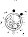
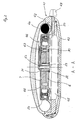
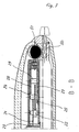
- Figures 1 to 3 show a preferred embodiment of the device according to the invention for displaying the moon phases, which is designed as a structural unit.
- the device consists of a moon ball 1, a first and second ring gear 2 and 3, a bearing ring 4 for the moon ball 1, a gear train 5, a base plate 6 and a cover plate 7.
- the first ring gear 2 has an internal toothing which has ninety-nine teeth and an annular section 11 which is formed on the circumference of the ring gear.
- the second ring gear 3 has an internal toothing which has one hundred and two teeth and a section 12 with an axial toothing which is formed on the circumference and has one hundred and nine teeth.
- the moon ball 1 has a shaft 14 provided with a pinion 13, which projects radially on one side and radially from the moon ball.
- the moon ball 1 is divided radially into a light and a dark half.
- the bearing ring 4 has a through hole 15 in which the free end of the shaft 14 is mounted.
- the bearing ring is connected to the first ring gear 2 by screws, not shown, which are screwed into threaded holes 16.
- a cutout 17 is formed, in which a section of the shaft 14 is mounted.
- the second ring gear 3 lies on the bearing ring 4 and engages with the axial toothing with the pinion 13 of the moon ball 1.
- the gear train 5 comprises a first drive 21 with pinion 22, which is in engagement with an hour tube 23, an intermediate wheel 24 with pinion 25, which is in engagement with the pinion 22, and a second drive 26.
- the second drive 26 has a first and second gear wheels 27 and 28, which are fixed at a distance on a common axis 29 such that the first gear wheel 27 is in engagement with the first ring gear 2 and with the second gear wheel 28 (FIGS. 1 and 2).
- the wheels of the gear train have a number of teeth which is less than 2/5 of the number of teeth of the sprockets 2 and 3.
- the first drive has thirty-six teeth and its pinion pinion has eleven teeth
- the idler gear has thirty-five teeth and its pinion sixteen teeth
- the first gear of the second drive thirty-six teeth and the second gear of the second drive thirty-three.
- the pinion of the moon ball has seven teeth.
- the first and second ring gear 2, 3, the pinion 13 of the moon ball 1 and the gear train 5 form a differential epicyclic planetary gear according to the invention.
- the bottom plate 6 and the top plate 7 are connected by screws 30 and form a substantially closed housing in which the planetary gear is arranged.
- Through holes 31, 32 are provided in the center of the two boards, the purpose of which will be explained later.
- the device described above is according to the invention in a watch, e.g. built in a wristwatch.
- the watch has a two-part housing 41 consisting of a central section bezel 42 and base 43, a watch glass 44, a watch mechanism 45, a minute hand 46, an hour hand 47, a dial 48 and an actuating device with a crown 49.
- a ring 50 is arranged in the watch case 41 and has a groove-shaped recess 51.
- the ring 50 is arranged below the plane of rotation of the moon ball 1 such that a section of the moon ball 1 projects into the recess 51.
- the assembly is mounted directly on the top of the clockwork 45.
- the minute tube 52 and the hour tube 23 protrude through the holes 31, 32 in the plates 6 and 7 in order to mount the corresponding pointers 46, 47.
- the dial 48 is arranged directly on the cover plate 7 and has an edge 54 in order to completely cover the cover plate (FIG. 2).
- the structural unit is arranged on the clockwork 45 such that the moon ball 1 over a imaginary sun is standing, the position of which is fixed in the 12 o'clock position of the clockwork 45, and that the moon ball 1 in the 12 o'clock position is directed towards the watch glass 44 with the dark half and towards the imaginary sun with the light half.
- a marking (not shown) can be provided on the watch case 41 or on the watch glass 44.
- the moon ball 1 is rotated by the hour tube 23 and the differential epicyclic planetary gear, formed by the pinion 13 of the moon ball, the sprockets 2 and 3 and the gear train 5.
- the moon ball is rotated via ten toothed links and seven axes .
- the hour tube 23 drives the first drive 21, the pinion 22 drives the intermediate wheel 24.
- the pinion 25 of the intermediate gear 24 meshes with the first gear 27 of the second drive, the second gear 28 rotates at the same speed.
- the first gear 27 rotates the first ring gear 2 with the bearing ring 4 and the moon ball 1 mounted therein, so that it rotates the dial clockwise.
- the second gear 28 rotates the second ring gear 3. Since the first and second ring gear 2, 3 and the first and second gear wheel 27, 28 of the second drive each have different numbers of teeth, the first and second ring gears 2 and 3 rotate at different speeds, the second ring gear 3 sliding on the bearing ring 4. Due to the speed difference of the two ring gears 2, 3, the moon ball 1, which engages with the second ring gear 3 via the pinion 13, performs a left-hand rotation.
- the moon is rotated clockwise once around the dial in 29.53 days and, on the other hand, performs its own rotation during this time, such that the bright section of moon ball 1 is always directed towards the imaginary sun and that the phases of the moon correspond to those in the sky visible is reproduced.
- the clockwork 45 is equipped with an additional adjusting wheel 55, which is in engagement with the first gear 27 of the second drive.
- the moon ball 1 is adjusted via the crown 49.
Landscapes
- Physics & Mathematics (AREA)
- Astronomy & Astrophysics (AREA)
- General Physics & Mathematics (AREA)
- Electric Clocks (AREA)
- Devices For Indicating Variable Information By Combining Individual Elements (AREA)
- Transmission Devices (AREA)
- Details Of Spanners, Wrenches, And Screw Drivers And Accessories (AREA)
Abstract
Description
- Die vorliegende Erfindung betrifft eine Vorrichtung zum Anzeigen der Mondphasen gemäss dem Oberbegriff des Anspruches 1 und eine Uhr mit einer derartigen Vorrichtung.
- Vorrichtungen zur Anzeige der Mondphasen sind bekannt. Die Bestandteile dieser Uhren sind einzeln in eine besondere Ausführungsform einer Uhr, einer sogenannten astronomischen Uhr integriert. Aus diesem Grunde sind derartige Vorrichtungen kompliziert im Aufbau und folglich Einzelanfertigungen, die teuer sind.
- Der Erfindung liegt die Aufgabe zugrunde eine Vorrichtung zum Anzeigen der Mondphasen zu schaffen, die ein einfach aufgebautes Getriebe mit einer geringen Anzahl von Einzelteilen und geringe Bauhöhe aufweist, und die als Baueinheit auf ein Uhrwerk montierbar ist.
- Diese Aufgabe wird erfindungsgemäss mit den kennzeichnenden Merkmalen des Anspruches 1 gelöst.
- Die mit der Erfindung erzielbaren Vorteile sind im wesentlichen darin zusehen, dass
- die Vorrichtung wenig Einzelelemente aufweist und einfach aufgebaut ist,
- die Vorrichtung maschinell hergestellt und montiert werden kann und
- die Vorrichtung eine geringe Bauhöhe aufweist, wodurch die Anwendungsmöglichkeiten vervielfacht werden können.
- Eine Uhr mit einer Vorrichtung zum Anzeigen der Mondphasen ist erfindungsgemäss durch die Merkmale des Anspruches 7 gekennzeichnet.
- Die Uhr hat den Vorteil, dass der aktuelle Stand des Mondes während einer Lunation zu jedem Zeitpunkt plastisch dargestellt wird.
- Vorteilhafte Ausführungsformen der Erfindung ergeben sich aus den abhängigen Ansprüchen.
- Im folgenden wird die Erfindung anhand der beiliegenden Zeichnungen erläutert.
- Es zeigen:
- Fig.1)
- eine Draufsicht auf ein Ausführungsbeispiel einer erfindungsgemässen Vorrichtung, welche das Getriebe darstellt,
- Fig.2)
- einen Schnitt entlang der Linie A-A in Figur 1,
- Fig.3)
- einen Schnitt entlang der Linie B-B in Figur 1 und
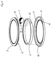
- Fig.4)
- eine Explosionszeichnung von Antriebsmitteln für eine Mondkugel.
- Die Figuren 1 bis 3 zeigen eine bevorzugte Ausführungsform der erfindungsgemässen Vorrichtung zum Anzeigen der Mondphasen, die als Baueinheit ausgebildet ist.
- Die Vorrichtung besteht aus einer Mondkugel 1, einem ersten und zweiten Zahnkranz 2 und 3, einem Lagerring 4 für die Mondkugel 1, einem Räderwerk 5, einer Bodenplatine 6 und einer Deckplatine 7.
- Wie die Figur 4 zeigt hat der erste Zahnkranz 2 eine Innenverzahnung, die neunundneunzig Zähne aufweist, und einen ringförmigen Abschnitt 11, der am Umfang des Zahnkranzes ausgebildet ist. Der zweite Zahnkranz 3 hat eine Innenverzahnung, die einhundertzwei Zähne aufweist, und einen Abschnitt 12 mit einer axialen Verzahnung, der am Umfang ausgebildet ist und einhundertundneun Zähne aufweist.
- Die Mondkugel 1 hat eine mit einem Ritzel 13 versehene Welle 14, die einseitig und radial von der Mondkugel absteht. Die Mondkugel 1 ist radial in eine helle und eine dunkle Hälfte unterteilt.
- Der Lagerring 4 hat ein Durchgangsloch 15 in welches das freie Ende der Welle 14 gelagert ist. Der Lagerring ist mit dem ersten Zahnkranz 2 durch nicht dargestellte Schrauben verbunden, die in Gewindelöchern 16 eingeschraubt sind. Im ringförmigen Abschnitt 11 des ersten Zahnkranzes 2 ist ein Ausschnitt 17 ausgebildet, in welchem ein Abschnitt der Welle 14 gelagert ist.
- Im montierten Zustand liegt der zweite Zahnkranz 3 auf dem Lagerring 4 und steht mit der axialen Verzahnung mit dem Ritzel 13 der Mondkugel 1 in Eingriff.
- Das Räderwerk 5 umfasst einen ersten Trieb 21 mit Ritzel 22, der mit einem Stundenrohr 23 in Eingriff steht, ein Zwischenrad 24 mit Ritzel 25, das mit dem Ritzel 22 in Eingriff steht, und einen zweiten Trieb 26. Der zweite Trieb 26 hat ein erstes und zweites Zahrad 27 und 28, die im Abstand auf einer gemeinsamen Achse 29 so befestigt sind, dass das erste Zahnrad 27 mit dem ersten Zahnkranz 2 und mit dem zweiten Zahnrad 28 in Eingriff steht (Fig.1 und 2).
- Bei der bevorzugten Ausführungsform haben die Räder des Räderwerkes eine Zähnezahl, die kleiner ist als 2/5 der Zähnezahl der Zahnkränze 2 und 3. Im einzelnen hat der der erste Trieb sechsunddreissig Zähne und dessen Ritzel Ritzel elf Zähne, das Zwischenrad fünfunddreissig Zähne und dessen Ritzel sechszehn Zähne, das erste Zahnrad des zweiten Triebes sechsunddreissig Zähne und das zweite Zahnrad des zweiten Triebes dreiunddreissig. Das Ritzel der Mondkugel hat sieben Zähne.
- Der erste und zweite Zahnkranz 2,3, das Ritzel 13 der Mondkugel 1 und das Räderwerk 5 bilden ein erfindungsgemässes differo-epizyklisches Planetenradgetriebe.
- Die Bodenplatine 6 und die Deckplatine 7 sind durch Schrauben 30 verbunden und bilden ein im wesentlichen geschlossenens Gehäuse, in welchem das Planetenradgetriebe angeordnet ist. Im Zentrum der beiden Platinen sind jeweils Durchgangslöcher 31,32 vorgesehen, deren Zweck später erläutert wird.
- Die vorstehend beschriebene Vorrichtung wird erfindungsgemäss in eine Uhr, z.B. eine Armbanduhr eingebaut. Die Uhr hat ein zweiteiliges Gehäuse 41 bestehend aus Mittelteil-Glasreif 42 und Boden 43, ein Uhrglas 44, ein Uhrwerk 45, einen Minutenzeiger 46, einen Stundenzeiger 47, ein Zifferblatt 48 und eine Stelleinrichtung mit einer Krone 49.
- Im Uhrgehäuse 41 ist ein Ring 50 angeordnet, der eine rinnenförmige Ausnehmung 51 aufweist. Der Ring 50 ist unterhalb der Rotationsebene der Mondkugel 1 so angeordnet, dass ein Abschnitt der Mondkugel 1 in die Ausnehmung 51 ragt.
- Wie Fig.2 zeigt, ist die Baueinheit direkt auf die Oberseite des Uhrwerkes 45 montiert. Das Minutenrohr 52 und das Stundenrohr 23 ragen durch die Bohrungen 31,32 in den Platinen 6 und 7, um die entsprechenden Zeiger 46,47 zu montieren. Das Zifferblatt 48 ist direkt auf der auf der Deckplatine 7 angeordnet und hat einen Rand 54, um die Deckplatine vollständig abzudecken ( Fig. 2 ).
- Die Baueinheit wird erfindungsgemäss so auf dem Uhrwerk 45 angeordnet, dass die Mondkugel 1 über einer gedachten Sonne steht, deren Stellung in der 12 Uhr Position des Uhrwerkes 45 festgelegt ist, und dass die Mondkugel 1 in der 12 Uhr Position mit der dunklen Hälfte zum Uhrglas 44 und mit der hellen Hälfte zur gedachten Sonne gerichtet ist. Um die Einstellung der Mondkugel 1 bezüglich der Sonne zu erleichtern, kann am Uhrgehäuse 41 oder am Uhrglas 44 eine Markierung (nicht dargestellt) vorgesehen werden.
- Die Drehung der Mondkugel 1 erfolgt durch das Stundenrohr 23 und über das differo-epizyklische Planetenradgetriebe, gebildet durch das Ritzel 13 der Mondkugel, die Zahnkränze 2 und 3 und das Räderwerk 5. Somit erfolgt die Drehung der Mondkugel erfindungsgemäss über zehn verzahnte Glieder und sieben Achsen.
- Das Stundenrohr 23 treibt den ersten Trieb 21, dessen Ritzel 22 das Zwischenrad 24 antreibt. Das Ritzel 25 des Zwischenrades 24 kämmt mit dem ersten Zahnrad 27 des zweiten Triebes, dessen zweites Zahnrad 28 mit der gleichen Drehzahl dreht. Das erste Zahnrad 27 dreht den ersten Zahnkranz 2 mit dem Lagerring 4 und der darin gelagerten Mondkugel 1, so dass diese im Uhrzeigersinn das Zifferblatt rotiert. Das zweite Zahnrad 28 dreht den den zweiten Zahnkranz 3. Da der erste und zweite Zahnkranz 2,3 sowie das erste und zweite Zahnrad 27,28 des zweiten Triebes jeweils unterschiedliche Zähnezahlen haben, rotieren der erste und zweite Zahnkranz 2 und 3 mit unterschiedlicher Drehzahl, wobei der zweite Zahnkranz 3 auf dem Lagerring 4 gleitet. Durch die Drehzahldifferenz der beiden Zahnkränze 2,3 führt die über das Ritzel 13 mit dem zweiten Zahnkranz 3 in Eingriff stehende Mondkugel 1 eine linksgängige Eigendrehung aus.
- Dadurch wird die Mondkugel einerseits in 29,53 Tagen einmal im Uhrzeigersinn um das Zifferblatt gedreht und führt andererseits die Eigendrehung in dieser Zeit aus, derart, dass der helle Abschnitt der Mondkugel 1 immer zur gedachten Sonne gerichtet ist und dass die Mondphasen gemäss der am Himmel sichtbaren wiedergegeben wird.
- Zur Verstellung der Mondkugel 1 ist das Uhrwerk 45 mit einem zusätzlichem Stellrad 55 ausgerüstet, das mit dem ersten Zahnrad 27 des zweiten Triebes in Eingriff steht. Die Verstellung der Mondkugel 1 erfolgt über die Krone 49. Es ist aber auch möglich eine separate Einstellvorrichtung vorzusehen.
Claims (8)
Applications Claiming Priority (2)
| Application Number | Priority Date | Filing Date | Title |
|---|---|---|---|
| CH1066/92 | 1992-04-02 | ||
| CH1066/92A CH684981B5 (de) | 1992-04-02 | 1992-04-02 | Vorrichtung zum Anzeigen der Mondphasen und Uhr mit einer derartigen Vorrichtung. |
Publications (2)
| Publication Number | Publication Date |
|---|---|
| EP0566529A1 true EP0566529A1 (de) | 1993-10-20 |
| EP0566529B1 EP0566529B1 (de) | 1997-06-04 |
Family
ID=4201658
Family Applications (1)
| Application Number | Title | Priority Date | Filing Date |
|---|---|---|---|
| EP93810233A Expired - Lifetime EP0566529B1 (de) | 1992-04-02 | 1993-04-01 | Vorrichtung zum Anzeigen der Mondphasen und Uhr mit einer derartigen Vorrichtung |
Country Status (4)
| Country | Link |
|---|---|
| EP (1) | EP0566529B1 (de) |
| AT (1) | ATE154146T1 (de) |
| CH (1) | CH684981B5 (de) |
| DE (1) | DE59306632D1 (de) |
Cited By (5)
| Publication number | Priority date | Publication date | Assignee | Title |
|---|---|---|---|---|
| WO2007099134A3 (fr) * | 2006-03-01 | 2007-11-15 | Vincent Plomb | Montre avec au moins un indicateur du temps a trois dimensions |
| EP2687918A1 (de) * | 2012-07-17 | 2014-01-22 | LVMH Swiss Manufactures SA | Mondphasenmechanismus |
| KR20170088430A (ko) * | 2014-12-31 | 2017-08-01 | 불랑패인쏘시에떼아노님 | 문 페이즈 인디케이터 메커니즘 |
| EP3483664A1 (de) * | 2017-11-10 | 2019-05-15 | Montres Breguet S.A. | Uhrmechanismus zum anzeigen des mondtags und der mondphase mit korrektursystem mit doppeltem antriebsstrang |
| CN113093505A (zh) * | 2019-12-23 | 2021-07-09 | 布朗潘有限公司 | 月相显示机构 |
Citations (2)
| Publication number | Priority date | Publication date | Assignee | Title |
|---|---|---|---|---|
| DE8906998U1 (de) * | 1989-06-08 | 1989-10-05 | Unkel, Manfred, Dipl.-Kaufm., 8000 München | Astronomische Jahresuhr |
| WO1991011756A1 (fr) * | 1990-01-25 | 1991-08-08 | Richard Jean Pierre | Dispositif de representation de la lune, notamment sur le cadran d'une montre |
-
1992
- 1992-04-02 CH CH1066/92A patent/CH684981B5/de not_active IP Right Cessation
-
1993
- 1993-04-01 EP EP93810233A patent/EP0566529B1/de not_active Expired - Lifetime
- 1993-04-01 DE DE59306632T patent/DE59306632D1/de not_active Expired - Fee Related
- 1993-04-01 AT AT93810233T patent/ATE154146T1/de not_active IP Right Cessation
Patent Citations (2)
| Publication number | Priority date | Publication date | Assignee | Title |
|---|---|---|---|---|
| DE8906998U1 (de) * | 1989-06-08 | 1989-10-05 | Unkel, Manfred, Dipl.-Kaufm., 8000 München | Astronomische Jahresuhr |
| WO1991011756A1 (fr) * | 1990-01-25 | 1991-08-08 | Richard Jean Pierre | Dispositif de representation de la lune, notamment sur le cadran d'une montre |
Non-Patent Citations (1)
| Title |
|---|
| JAHRBUCH DER DEUTSCHEN GESELLSCHAFT FüR CHRONOMETRIE Bd. 40, 1989, STUTTGART DEUTSCHLAND Seiten 139 - 161 G.GLASER 'Astronomische Indikationen bei Uhren' * |
Cited By (13)
| Publication number | Priority date | Publication date | Assignee | Title |
|---|---|---|---|---|
| WO2007099134A3 (fr) * | 2006-03-01 | 2007-11-15 | Vincent Plomb | Montre avec au moins un indicateur du temps a trois dimensions |
| JP2009528526A (ja) * | 2006-03-01 | 2009-08-06 | プロン、バンサン | 少なくとも一つの三次元時刻インジケータを有する腕時計 |
| US7859948B2 (en) | 2006-03-01 | 2010-12-28 | Vincent Plomb | Watch with at least one three-dimensional time indicator |
| CN101432667B (zh) * | 2006-03-01 | 2011-09-21 | 文森特·普隆布 | 具有至少一个三维时间指示器的表 |
| EP2687918A1 (de) * | 2012-07-17 | 2014-01-22 | LVMH Swiss Manufactures SA | Mondphasenmechanismus |
| CH706748A1 (fr) * | 2012-07-17 | 2014-01-31 | Lvmh Swiss Mft Sa | Mécanisme de phase de lune. |
| KR20170088430A (ko) * | 2014-12-31 | 2017-08-01 | 불랑패인쏘시에떼아노님 | 문 페이즈 인디케이터 메커니즘 |
| JP2017538119A (ja) * | 2014-12-31 | 2017-12-21 | ブランパン・エス アー | 月相表示機構 |
| EP3483664A1 (de) * | 2017-11-10 | 2019-05-15 | Montres Breguet S.A. | Uhrmechanismus zum anzeigen des mondtags und der mondphase mit korrektursystem mit doppeltem antriebsstrang |
| CN109765775A (zh) * | 2017-11-10 | 2019-05-17 | 宝玑表有限公司 | 具有使用双运动链的校正系统的用于显示阴历日和月相的钟表机械装置 |
| US11036185B2 (en) | 2017-11-10 | 2021-06-15 | Montres Breguet S.A. | Timepiece mechanism for displaying the lunar day and moon phase, with a correction system using a double kinematic chain |
| CN113093505A (zh) * | 2019-12-23 | 2021-07-09 | 布朗潘有限公司 | 月相显示机构 |
| US11940760B2 (en) | 2019-12-23 | 2024-03-26 | Blancpain Sa | Moon phase display mechanism |
Also Published As
| Publication number | Publication date |
|---|---|
| ATE154146T1 (de) | 1997-06-15 |
| EP0566529B1 (de) | 1997-06-04 |
| DE59306632D1 (de) | 1997-07-10 |
| CH684981GA3 (de) | 1995-02-28 |
| CH684981B5 (de) | 1995-08-31 |
Similar Documents
| Publication | Publication Date | Title |
|---|---|---|
| DE69306054T2 (de) | Weltzeituhr | |
| DE3036165C3 (de) | Uhr zur analogen Anzeige der Zeit | |
| DE69309884T2 (de) | Uhrwerk mit zwei entgegengesetzten Analoganzeigen | |
| EP0529191B1 (de) | Datumsanzeige einer Uhr | |
| DE1805915A1 (de) | Zeitzonenumschaltmechanismus in einer Uhr | |
| DE10050557C1 (de) | Uhrenanzeigevorrichtung | |
| DE69826248T2 (de) | Uhr mit angabe des aufzeichnungszustandes der zugfeder | |
| DE2632303A1 (de) | Batteriebetriebene elektronische uhr | |
| DE602005001612T2 (de) | Uhr mit Zeitperiodeanzeige | |
| EP0566529B1 (de) | Vorrichtung zum Anzeigen der Mondphasen und Uhr mit einer derartigen Vorrichtung | |
| DE69000423T2 (de) | Astronomische uhr mit einem teil, der die bewegung eines himmelskoerpers simuliert. | |
| DE4330895A1 (de) | Uhr mit rotierenden Anzeigeelementen | |
| DE3940254C2 (de) | ||
| DE2230289B2 (de) | Kanalanzeigevorrichtung fuer einen uhf-tuner | |
| DE3832271C2 (de) | ||
| DE3918647C2 (de) | Uhr mit einer Darstellung der Mondphasen | |
| DE2524414A1 (de) | Digitaluhr mit mechanischem gangwerk | |
| DE60025745T2 (de) | Mechanisches uhrwerk mit kleiner oder mittelsekunde | |
| DE3527125C1 (de) | Armbanduhr | |
| DE69215412T2 (de) | Uhr | |
| DE3602976C2 (de) | ||
| DE7933304U1 (de) | Zeigeruhr, insbesondere Armbanduhr | |
| DE602004008207T2 (de) | Kalendermechanismus | |
| DE102024002702B3 (de) | Uhr | |
| DE8122416U1 (de) | Elektronische Uhr mit Analoganzeige |
Legal Events
| Date | Code | Title | Description |
|---|---|---|---|
| PUAI | Public reference made under article 153(3) epc to a published international application that has entered the european phase |
Free format text: ORIGINAL CODE: 0009012 |
|
| AK | Designated contracting states |
Kind code of ref document: A1 Designated state(s): AT BE CH DE DK ES FR GB GR IE IT LI LU MC NL PT SE |
|
| RBV | Designated contracting states (corrected) |
Designated state(s): AT BE DE FR GB LU NL |
|
| 17P | Request for examination filed |
Effective date: 19940409 |
|
| 17Q | First examination report despatched |
Effective date: 19951128 |
|
| GRAG | Despatch of communication of intention to grant |
Free format text: ORIGINAL CODE: EPIDOS AGRA |
|
| GRAH | Despatch of communication of intention to grant a patent |
Free format text: ORIGINAL CODE: EPIDOS IGRA |
|
| GRAH | Despatch of communication of intention to grant a patent |
Free format text: ORIGINAL CODE: EPIDOS IGRA |
|
| GRAA | (expected) grant |
Free format text: ORIGINAL CODE: 0009210 |
|
| AK | Designated contracting states |
Kind code of ref document: B1 Designated state(s): AT BE DE FR GB LU NL |
|
| REF | Corresponds to: |
Ref document number: 154146 Country of ref document: AT Date of ref document: 19970615 Kind code of ref document: T |
|
| GBT | Gb: translation of ep patent filed (gb section 77(6)(a)/1977) |
Effective date: 19970606 |
|
| REF | Corresponds to: |
Ref document number: 59306632 Country of ref document: DE Date of ref document: 19970710 |
|
| ET | Fr: translation filed | ||
| PLBE | No opposition filed within time limit |
Free format text: ORIGINAL CODE: 0009261 |
|
| STAA | Information on the status of an ep patent application or granted ep patent |
Free format text: STATUS: NO OPPOSITION FILED WITHIN TIME LIMIT |
|
| 26N | No opposition filed | ||
| REG | Reference to a national code |
Ref country code: GB Ref legal event code: IF02 |
|
| PGFP | Annual fee paid to national office [announced via postgrant information from national office to epo] |
Ref country code: NL Payment date: 20040226 Year of fee payment: 12 |
|
| PGFP | Annual fee paid to national office [announced via postgrant information from national office to epo] |
Ref country code: AT Payment date: 20040423 Year of fee payment: 12 |
|
| PGFP | Annual fee paid to national office [announced via postgrant information from national office to epo] |
Ref country code: BE Payment date: 20040426 Year of fee payment: 12 Ref country code: LU Payment date: 20040426 Year of fee payment: 12 |
|
| PGFP | Annual fee paid to national office [announced via postgrant information from national office to epo] |
Ref country code: FR Payment date: 20040427 Year of fee payment: 12 |
|
| PG25 | Lapsed in a contracting state [announced via postgrant information from national office to epo] |
Ref country code: LU Free format text: LAPSE BECAUSE OF NON-PAYMENT OF DUE FEES Effective date: 20050401 Ref country code: AT Free format text: LAPSE BECAUSE OF NON-PAYMENT OF DUE FEES Effective date: 20050401 |
|
| PG25 | Lapsed in a contracting state [announced via postgrant information from national office to epo] |
Ref country code: BE Free format text: LAPSE BECAUSE OF NON-PAYMENT OF DUE FEES Effective date: 20050430 |
|
| BERE | Be: lapsed |
Owner name: S.A. *BUNZ MONTRES Effective date: 20050430 |
|
| PG25 | Lapsed in a contracting state [announced via postgrant information from national office to epo] |
Ref country code: NL Free format text: LAPSE BECAUSE OF NON-PAYMENT OF DUE FEES Effective date: 20051101 |
|
| PG25 | Lapsed in a contracting state [announced via postgrant information from national office to epo] |
Ref country code: FR Free format text: LAPSE BECAUSE OF NON-PAYMENT OF DUE FEES Effective date: 20051230 |
|
| NLV4 | Nl: lapsed or anulled due to non-payment of the annual fee |
Effective date: 20051101 |
|
| REG | Reference to a national code |
Ref country code: FR Ref legal event code: ST Effective date: 20051230 |
|
| PGFP | Annual fee paid to national office [announced via postgrant information from national office to epo] |
Ref country code: DE Payment date: 20060217 Year of fee payment: 14 |
|
| PGFP | Annual fee paid to national office [announced via postgrant information from national office to epo] |
Ref country code: GB Payment date: 20060426 Year of fee payment: 14 |
|
| GBPC | Gb: european patent ceased through non-payment of renewal fee |
Effective date: 20070401 |
|
| BERE | Be: lapsed |
Owner name: S.A. *BUNZ MONTRES Effective date: 20050430 |
|
| PG25 | Lapsed in a contracting state [announced via postgrant information from national office to epo] |
Ref country code: DE Free format text: LAPSE BECAUSE OF NON-PAYMENT OF DUE FEES Effective date: 20071101 |
|
| PG25 | Lapsed in a contracting state [announced via postgrant information from national office to epo] |
Ref country code: GB Free format text: LAPSE BECAUSE OF NON-PAYMENT OF DUE FEES Effective date: 20070401 |