EP0566530A2 - Ensemble d'éléments pour un dispositif d'arrêt pour maintenir une fenêtre au moins entre-ouverte - Google Patents
Ensemble d'éléments pour un dispositif d'arrêt pour maintenir une fenêtre au moins entre-ouverte Download PDFInfo
- Publication number
- EP0566530A2 EP0566530A2 EP93810236A EP93810236A EP0566530A2 EP 0566530 A2 EP0566530 A2 EP 0566530A2 EP 93810236 A EP93810236 A EP 93810236A EP 93810236 A EP93810236 A EP 93810236A EP 0566530 A2 EP0566530 A2 EP 0566530A2
- Authority
- EP
- European Patent Office
- Prior art keywords
- frame
- bolt
- kit
- window
- sash
- Prior art date
- Legal status (The legal status is an assumption and is not a legal conclusion. Google has not performed a legal analysis and makes no representation as to the accuracy of the status listed.)
- Ceased
Links
Images

Classifications
-
- E—FIXED CONSTRUCTIONS
- E05—LOCKS; KEYS; WINDOW OR DOOR FITTINGS; SAFES
- E05C—BOLTS OR FASTENING DEVICES FOR WINGS, SPECIALLY FOR DOORS OR WINDOWS
- E05C17/00—Devices for holding wings open; Devices for limiting opening of wings or for holding wings open by a movable member extending between frame and wing; Braking devices, stops or buffers, combined therewith
- E05C17/02—Devices for holding wings open; Devices for limiting opening of wings or for holding wings open by a movable member extending between frame and wing; Braking devices, stops or buffers, combined therewith by mechanical means
- E05C17/04—Devices for holding wings open; Devices for limiting opening of wings or for holding wings open by a movable member extending between frame and wing; Braking devices, stops or buffers, combined therewith by mechanical means with a movable bar or equivalent member extending between frame and wing
-
- E—FIXED CONSTRUCTIONS
- E05—LOCKS; KEYS; WINDOW OR DOOR FITTINGS; SAFES
- E05B—LOCKS; ACCESSORIES THEREFOR; HANDCUFFS
- E05B17/00—Accessories in connection with locks
- E05B17/06—Templates for marking the position of apertures in fittings of wings or frames; Apparatus for installation of a lockset
-
- E—FIXED CONSTRUCTIONS
- E05—LOCKS; KEYS; WINDOW OR DOOR FITTINGS; SAFES
- E05B—LOCKS; ACCESSORIES THEREFOR; HANDCUFFS
- E05B63/00—Locks or fastenings with special structural characteristics
- E05B63/0004—Additional locks added to existing lock arrangements
-
- E—FIXED CONSTRUCTIONS
- E05—LOCKS; KEYS; WINDOW OR DOOR FITTINGS; SAFES
- E05B—LOCKS; ACCESSORIES THEREFOR; HANDCUFFS
- E05B63/00—Locks or fastenings with special structural characteristics
- E05B63/04—Locks or fastenings with special structural characteristics for alternative use on the right-hand or left-hand side of wings
-
- E—FIXED CONSTRUCTIONS
- E05—LOCKS; KEYS; WINDOW OR DOOR FITTINGS; SAFES
- E05B—LOCKS; ACCESSORIES THEREFOR; HANDCUFFS
- E05B9/00—Lock casings or latch-mechanism casings ; Fastening locks or fasteners or parts thereof to the wing
- E05B9/08—Fastening locks or fasteners or parts thereof, e.g. the casings of latch-bolt locks or cylinder locks to the wing
Definitions
- the invention relates to a kit according to the preamble of patent claims 1 and 6.
- Under a reach-wide opening pivot position of a window or a door is understood to mean an opening between the sash and frame, which is so large that it can be reached through or at least with an object such as. B. a bent wire can be reached to z. B. "fishing out" objects from the living room or hereby actuating an actuator for an adjusting device for fully opening the casement.
- a generic kit is known from EP-A 0 477 485.
- the heel has, as components to be attached to the sash and frame, a housing arranged on the sash frame with a spring-loaded mushroom-shaped catch pin which can be pulled in via a pawl and a slotted extension arm held on the frame with a pivot bearing.
- the slot width is chosen so that when the frame is closed, the head of the catch pin can be inserted into the slot and the opening arm is taken along when the wing is swung open. In the outer area, the slot width is reduced so that the catch pin can no longer be pulled out of the slot.
- the catch pin can only be removed when the window is closed, which means that it is safe to insert.
- the sash is held in its open position by a "sliding clamp seat" caused by the spring force of the tab. The holding force should be so small, however, that the sash should be slammed even with small gusts of wind.
- kits are known from CA-A 898 304.
- the known kit consists of a latch holder to be arranged on the casement frame, the latch of which can be locked in several positions and can be inserted into a longitudinal slot of a pivoting arm arranged on the frame. It is not possible to fix the casement in an open position, slamming against wind gusts, but security against creeping is provided insofar as the bolt from the longitudinal slot is only possible when the casement is closed.
- a kit similar to this is known from DE-C 44 038.
- the kit known from DE-A 35 21 492 has a fitting plate arranged on the window frame face with a flange having a fork-like open sliding seat.
- a housing with a fold-out connecting piece is arranged on the rollover peripheral surface of the casement.
- the connecting piece can be swiveled out and can be coupled with its free end into the sliding seat with the creation of an opening angle between the sash and frame. In its issued position, the connector can be locked so that the opening angle is fixed.
- the free end of the connecting piece remains in the sliding seat even when the sash frame is closed and can only be disengaged from it by actuating a push button and fixed in the disengaged position with a grub screw.
- a kit to be attached to a sash and window frame to hold the sash frame open in a slot is sold as a product by Siegenia-Frank KG, PO Box 10 05 01, D-W-5900 Siegen as a so-called AEROfix night vent.
- the known slot fan has a switch housing that can be attached to the sash frame, with a rocker through which a pin can be extended and retracted, and a holding block to be attached to the frame with a recess that the pin engages with.
- the recess is arranged in such a way that when the pin is locked in it, the casement is opened in a gap.
- the gap held by the gap opener must always be so small that there is no direct passage or view between the interlocking shoulders of the sash and frame, otherwise a narrow object could be inserted with which the Rocker could be moved and so that the door for creeping in could be freely pivoted.
- the invention has for its object to provide a mountable to the frame kit for a window or door locking device with at least one reach-wide, creep-proof opening pivot position, which swivels the sash frame into its opening pivot position and fixes the sash in this position such that a Gust of wind does not slam the wing.
- a penetration-wide opening is understood to be an at least thumb-wide, clear view between the sash and window frame on the side opposite the pivot bearing, so that there is good airflow exchange through the opening is possible.
- kit parts of the window locking device can be attached without any frame material recesses to the built-in frame in the house wall and the sash frame hung in the frame, these can also be easily installed by non-specialist. This makes it easy to retrofit old windows.
- the coupling members are designed in such a way that coupling or uncoupling is only possible when the window or door is closed. I.e. Sneaking into the apartment by completely opening the window or door from the outside is not possible, since the slot released by the device is always so small that a person cannot squeeze through it and the window is only closed before it can be opened freely got to.
- the components can be easily attached to the frame by the non-specialist in the correct position.
- kits Another advantage of the kit is that the adjusting device part can be fastened to both the sash and the frame and the holding kit part can then be fastened analogously to the frame and sash. As a result, installation is possible both on wings which can be pivoted into the living space and on wings which can be pivoted outwards.
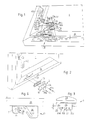
- the kit shown in Figures 1 and 2 in an exploded view for a device for locking and adjusting a window 1 has an adjusting device part 3, as a holding kit part a bearing block 5 with a pivotally mounted bracket 7 as a connecting element and a mounting template 9 and more Shims 11a and 11b and 13.
- adjusting device component part 3 for fastening the adjusting device component part 3 to the casement 15 of the window 1 there are two wood screws 17a and 17b which can be inserted through the through holes 16 and three wood screws 19a, 19b and 19c for fastening of the bearing block 5 on the frame 21 available.
- a handle 23 is mounted in the adjusting device component part 3, by the rotation of which a plate 24 with three bolts 26a, 26b and 26c on the underside along a slot 25 into a central position - as shown in FIGS. 1 and 3 - and two lateral positions - of which one shown in Figure 2 - is adjustable by turning the handle 23.
- the two bolts 26a and 26c (as the first and first and third bolts) are symmetrical to the middle (second) bolt 26b, which is the only one having a bolt head 27, with bolt axes which lie in a plane parallel to the surface of the sash 15, i . H. to the contact surface of the adjusting device component part 3 on the casement 15.
- the bolt 26b serves as a stop element and the bolt 26a or 26c, depending on whether it is a wing that swings to the left or right, as the second stop element.
- the space between the bolts 26b and 26a or between 26b and 26c is chosen to be so large that either the fork tine 40a or 40b described below can be at least partially inserted as a third stop element.
- a cam 26d is arranged on the left side of the plate 24 in FIG. 1 and serves to grip the swiveled-out tab 7 and to take it along when the sash 15 is swiveled shut.
- the bearing block 5 is formed from a sheet metal bent at right angles with a foot part 30 having three, preferably chamfered through holes 29a 29 and 29c for fastening screws 17a, 17b and 17c.
- the tab 7 is mounted with a self-locking pivot bearing 33.
- the side 31 has a U-shaped recess 35a and 35b on both sides, the legs 36a and 36b of which are adjacent to the foot part 30 as a leading edge for the bolt 26c and for the bolt 26a, respectively, if it is a window (not shown) opening on the right acts, is extended.
- the center line of the recesses 35a and 35b is further away from the contact surface of the foot part 30 on the frame 21 by a distance than the difference between the normal thickness n of the wing frame part 37 projecting beyond the frame 21 when the window is closed and the distance a shown in FIG Axis of the bolt 26a or 26c from the contact surface of the adjusting device component part 3 on the upper side of the sash frame.
- This arrangement of the recesses 35a and 35b relative to the bolts 26a and 26c, as described below, makes it possible to open the window 1 in a slot-like manner only.
- the link head 39 of the link 7 facing away from the pivot bearing 33 is designed as a cranked fork with two fork tines 40a and 40b, as shown in an enlarged illustration in FIG.
- the fork tines 40a and 40b are angled upward at right angles from the base plate body, towards the outside of the side 31.
- the angled tine length corresponds approximately to the height of the bolts 26a, 26b and 26c.
- the tab head 39 is set back in the direction opposite to the tine bend due to a double bend 41.
- the gap 42 between the two fork tines 40a and 40b is chosen so large that only the bolt 26a or 26c, but not the bolt 26b, can slip through.
- the broad tine surfaces are chosen so large that the bolt 26a or 26c always strikes against the lug head 29 pivoted about the bolt 26c by the maximum angle of inclination and does not slide past to the side.
- the maximum swivel angle results from the maximum opening angle of the window that can be reached with the assembled kit, provided the window cannot be swiveled freely.
- tab delimitations 43a and 43b Immediately adjacent to the angled fork tines 40a and 40b are two bent-up tab delimitations 43a and 43b on each longitudinal link side in the area of the link head 39.
- the tab delimitations 43a and 43b are bent inwards like a roof, so that the bolt head 27 cannot slip over the edges of the inwardly bent tab delimitations 43a and 43b, but the bolts 26a and 26c can slip through. This prevents the tab head 39 from slipping downward.
- the rotary movement of the handle 23 can be blocked with a lock, the keyhole 44 of which can be seen on the top of the handle. Blocking the rotation of the handle is intended as a child lock so that children cannot fully open a slot-shaped window, especially since the device is usually attached to the lower side of the window and is therefore easily accessible for children.
- the plate 24 with its three bolts 26a, 26b and 26c forms the one coupling member and the link head 39 with its roof-like inwardly bent tab borders 43a and 43b and the fork tines 40a and 40b the other coupling member.
- the interaction of the two coupling members is described below in connection with the different positions of the casement 15.
- the assembly template 9 As shown in FIG. 2, is placed on the sash frame 15 at the location at which the adjusting device component part 3 is to be mounted. The closer the location is to the window pivot bearing (window hinge) (not shown), the greater the adjustable opening pivot angle of window 1 will be.
- the assembly template 9 is placed on the sash 15 so that the designation of the holes A is visible and the other side of the assembly jig 9 rests on the casement part 37.
- the holes A are pre-drilled and depending on the width of the casement part 37, the adjusting device component part 3 is screwed on with or without a washer 13 using the screws 19a and 19b. Screwing on is only possible if the handle 23 is in the position shown in FIG. 2.
- the adjustment device component part 3 After the adjustment device component part 3 has been screwed on, its handle 23 is rotated into the position shown in FIG. As a result, the plate 24 is shifted into its central position in the slot 25.
- the assembly jig 9 is now struck in the position shown in FIG. 1 with the window 1 closed on the casement part 37 in such a way that the designations B can be read at the corresponding openings.
- the sash frame 15 is pre-drilled through the openings and the bearing block 5 is screwed on with the screws 17a, 17b and 17c. If, what can happen with older casements, the thickness of the part of the casement 37 projecting beyond the frame 21 deviates from the standard thickness n, then one or both washers 11a and 11b may have to be used.
- the tab 7 To screw the bearing block 5, the tab 7 is advantageously pivoted in a direction away from the frame 21.
- FIGS. 5a to 5e The mode of operation of the kit installed on the window sash and window frame 15 and 21 can be seen from FIGS. 5a to 5e, with a passage-wide sash opening being achieved in FIGS. 5c to 5d.
- Figure 5a shows the closed window; Glare and casement frames 21 and 15 are leaned against each other.
- the frame / sash position and the position of the handle 23 of the installed adjusting device part 3 correspond to the position as described above after assembly.
- the tab head 39 abuts the frame 21 and the plate 24 is in its central position, as shown in Figures 1 and 3.
- the window 1 can, as long as the window lock handle 45 is opened, be pivoted freely, since all three bolts 26a, 26b and 26c can be pivoted between the bracket head 39 and the pivot bearing 33.
- the bolt 26c slips over the leg 36b into the recess 35a.
- the center line of the recess 35a extends from the bearing surface of the foot part 30, i.e. is a distance further away from the surface of the frame 21 by a distance than the difference between the normal thickness n of the sash frame part 37 projecting above the frame 21 and the distance a of the axis of the bolt 26a or 26c from the contact surface of the adjusting device part 3 on the sash frame top, the sash is pushed away from the frame 21 such that a slot 49 is formed between them.
- the handle is turned a quarter of a turn counterclockwise, as indicated by the arrow 55, the bolt 26a presses against the outer fork surface and thus presses the tab 7 forms an acute angle to the sash frame 15 , at its other end, is pivotally held in the bearing block 5 on the frame 21 and the bolt 26b presses on the sash border 43a facing away from the frame 21, so that the opening gap 53 is enlarged to an opening gap 56.
- a coupling of the adjusting device component 3 to the strap head 39 is only possible if the window sash 15 is opened as far as it will go, forming the gap 53.
- the sash frame 15 is locked in the pivot positions shown in FIGS. 5b to 5e by means of catches present in the adjusting device component part 3, which hold the handle 23 in every quarter position, from which it can only be turned further with increased effort.
- catches present in the adjusting device component part 3 which hold the handle 23 in every quarter position, from which it can only be turned further with increased effort.
- a spring-loaded ball can be used, which engages in a groove.
- the above assembly description is based on a window 1 to be opened on the left.
- the components of the kit can also be used for a window that can be swung open on the right.
- the stiffener kit 3 is placed to the left of the vertical casement strut and the assembly gauge 9 is applied to the plate 24 on the left.
- the tab 7 is then folded to the right.
- the pin 26a then engages in the U-shaped recess 35b to produce a slot opening of the casement analogous to the slot opening 49.
- the bolt 26c is located on the broad outer surface of the tine.
- the kit parts can also be fastened to the vertical casement frame and the adjacent frame part. In this case, only the handle positions are rotated by an angle of 90 ° to the positions shown in FIGS. 1 to 5.
- the adjusting device component part can also be attached to the frame and the other kit parts to the sash frame.
- the dimensions of the components are only to be chosen here in such a way that the handle does not prevent the sash frame from swinging open.
- kit parts can also be mounted on a door.
- the U-shaped recesses are preferably integrated in the bearing block 5, but they could also be arranged in a separate angle piece, separated from the bearing block.
- the bolts 26c or 26a and the U-shaped recess 35a or 35b can be dispensed with. In view of its limited possible uses, however, this type of design is to be regarded as a poorer type of design.
- a holding kit part 63 shown in FIG. 6 can also be used.
- the holding kit part 63 is shown against the viewing direction 111 shown in FIG. 1 for easier understanding.
- the slot width is selected such that the bolt 26b of the plate 24 can be displaced in the slot 67 as a display part with a clearance fit.
- the bolts 26a and 26c are no longer required in this variant of the kit.
- the wing 15 can be opened freely. However, if the bolt 26b is inserted with the plate 24 into the slot 67, the wing 15 is swung open, since the inclination of the slot is chosen such that it does not correspond to a tangent to a circle which is the center of the pivot bearing of the wing 15 and has the distance of the assembled mounting kit part 63 from the wing pivot bearing as a radius.
- a further flange 71 is arranged parallel to the flange 66, which has a recess 72 open to the free space 69, which is covered with a rubber-elastic plate 73 which protrudes into the recess 72.
- the size of the protruding part 75 of the plate 73 is now chosen so large that the bolt 26b is pressed against the part 75 in one of the latching positions of the handle 23 in such a way that such a large elastic impression is created that the sash 15 due to the elastic restoring force of the rubber-elastic material is fixed in its position.
- the slot width can be adjusted depending on the spacing of the bolt 26b from the frame 21 in the recess 72.
- FIG. 7 An embodiment variant of a lock 77 arranged in the handle 23, the keyhole in FIG gur 1 with 44 is shown in Figure 7.
- the lock 77 shown in FIG. 7 in the closed position has a bolt 79 which is seated in a threaded through bore 80 and a bore 81 in the part of the adjusting device part fastened to the sash 15.
- a transverse bore 83 is arranged, in which a pin 85 made of rubber-elastic material is located.
- the length of the pin 85 is a tolerance greater than the thread diameter of the threaded through bore 80, whereby the pin ends press into the threads so that the bolt 79 can be rotated out of the threaded through hole 80 by turning a key inserted into the keyhole 44 until the bolt end no longer protrudes into the bore 81 and thus the handle 23 is freely rotatable.
- the rubber-elastic clamping force in the threads is only so great that the pin 79 can be inserted by thumb pressure.
Landscapes
- Engineering & Computer Science (AREA)
- Mechanical Engineering (AREA)
- Hinges (AREA)
- Wing Frames And Configurations (AREA)
Applications Claiming Priority (2)
| Application Number | Priority Date | Filing Date | Title |
|---|---|---|---|
| CH01070/92A CH688936A5 (de) | 1992-04-02 | 1992-04-02 | Bausatz fuer eine Vorrichtung zur Fest- und Verstellung eines Fensters oder einer Tuere in wenigstens einer durchgriffbreiten, einschleichsicheren Oeffnungsschwenklage. |
| CH1070/92 | 1992-04-02 |
Publications (2)
| Publication Number | Publication Date |
|---|---|
| EP0566530A2 true EP0566530A2 (fr) | 1993-10-20 |
| EP0566530A3 EP0566530A3 (fr) | 1994-11-23 |
Family
ID=4201750
Family Applications (1)
| Application Number | Title | Priority Date | Filing Date |
|---|---|---|---|
| EP19930810236 Ceased EP0566530A3 (fr) | 1992-04-02 | 1993-04-02 | Ensemble d'éléments pour un dispositif d'arrêt pour maintenir une fenêtre au moins entre-ouverte. |
Country Status (2)
| Country | Link |
|---|---|
| EP (1) | EP0566530A3 (fr) |
| CH (1) | CH688936A5 (fr) |
Cited By (2)
| Publication number | Priority date | Publication date | Assignee | Title |
|---|---|---|---|---|
| CN104975753A (zh) * | 2015-07-08 | 2015-10-14 | 蔡德林 | 一种连接牢固的拉手锁 |
| US11951811B1 (en) * | 2023-10-05 | 2024-04-09 | Bradley Wing | Kit for retrofitting a pivoting window of a vehicle |
Family Cites Families (12)
| Publication number | Priority date | Publication date | Assignee | Title |
|---|---|---|---|---|
| DE44038C (de) * | FR. WAMSLER, Königl. Hoflieferant in München, Schellingstr. 73 | Automatischer Sicherheitsverschlufs für Thüren | ||
| US2834627A (en) * | 1954-09-17 | 1958-05-13 | George Moses | Door spacer |
| DE1125991B (de) * | 1955-01-31 | 1962-03-22 | Siemens Ag | Elektrische Abzweigdose |
| US3232160A (en) * | 1964-09-09 | 1966-02-01 | Long Lok Corp | Self-locking pin |
| CA898304A (en) * | 1970-06-11 | 1972-04-18 | Levy-Bencheton Jaime | Entrebailleur de porte a usage double |
| US3770036A (en) * | 1972-01-31 | 1973-11-06 | Lamson & Sessions Co | Fastener |
| DE2452614A1 (de) * | 1974-11-06 | 1976-05-13 | Bosch Gmbh Robert | Verbindungselement mit einem kopf und einem schaft |
| GB2064639B (en) * | 1979-11-30 | 1983-06-08 | Securistyle Ltd | Window fasteners |
| DE3250129C2 (de) * | 1982-06-25 | 1999-04-08 | Winkhaus Fa August | Drehkippfenster oder Drehkipptüre |
| FR2609761A1 (fr) * | 1987-01-19 | 1988-07-22 | Sarran Ets | Goupille autobloquante |
| CH678559A5 (fr) * | 1989-01-25 | 1991-09-30 | Schaerer Soehne Ag Usm U | |
| DE4029302A1 (de) * | 1990-09-15 | 1992-03-19 | Fuhr Carl Gmbh & Co | An fluegeln von fenstern, tueren oder dergleichen anzuschlagende vorrichtung zur begrenzung des oeffnungsweges |
-
1992
- 1992-04-02 CH CH01070/92A patent/CH688936A5/de not_active IP Right Cessation
-
1993
- 1993-04-02 EP EP19930810236 patent/EP0566530A3/fr not_active Ceased
Cited By (2)
| Publication number | Priority date | Publication date | Assignee | Title |
|---|---|---|---|---|
| CN104975753A (zh) * | 2015-07-08 | 2015-10-14 | 蔡德林 | 一种连接牢固的拉手锁 |
| US11951811B1 (en) * | 2023-10-05 | 2024-04-09 | Bradley Wing | Kit for retrofitting a pivoting window of a vehicle |
Also Published As
| Publication number | Publication date |
|---|---|
| EP0566530A3 (fr) | 1994-11-23 |
| CH688936A5 (de) | 1998-06-15 |
Similar Documents
| Publication | Publication Date | Title |
|---|---|---|
| EP0678636B1 (fr) | Elément de connection pour l'installation du battant d'un vasistas de toiture dans le caisson d'entourage | |
| DE3320824C2 (fr) | ||
| EP0786574B1 (fr) | Ferrure pour verrouiller un battant d'une fênetre ou d'une porte à un dormant | |
| EP0277286A1 (fr) | Ferrure de charnière pour fenêtres, portes ou similaire | |
| DE69805903T2 (de) | Beschlag mit einstellbarem Riegel für Schiebeflügel | |
| DE3637077C1 (de) | Scharniergelenk fuer Fenster,Tueren od.dgl. | |
| DE2460402A1 (de) | Ausstellvorrichtung fuer kipp- drehfluegel von fenstern, tueren od. dgl. | |
| EP1411201A2 (fr) | Ferrure | |
| EP0340456B1 (fr) | Palier de compas pour fenêtre oscillo-battante | |
| DE4128486C2 (de) | Verschlußvorrichtung für Flügel | |
| DE3004854C2 (de) | Feststellvorrichtung für Flügel von Fenstern, Türen o.dgl. in wenigstens einer Spaltlüftungsstellung | |
| EP0380440B1 (fr) | Porte ou fenêtre | |
| DE3619682A1 (de) | Ausstellvorrichtung fuer die fluegel von fenstern, tueren od. dgl. mit zuschlagsicherung fuer den geoeffneten fluegel | |
| EP0566530A2 (fr) | Ensemble d'éléments pour un dispositif d'arrêt pour maintenir une fenêtre au moins entre-ouverte | |
| DE3429699A1 (de) | Fehlbedienungssperre fuer treibstangenbeschlaege | |
| DE19902579C2 (de) | Verschlußvorrichtung für den unterschlagenden Flügel zweiflügeliger setzholzloser Fenster oder Türen | |
| EP0199270B1 (fr) | Dispositif pour maintenir une porte ou une fenêtre entrouverte dans au moins une position | |
| DE10056607C1 (de) | Fehlbedienungssperre für Treibstangenbeschläge | |
| EP0457170A1 (fr) | Charnière | |
| DE69808038T2 (de) | Verbesserung der gelenkigen Verbindung eines Flügels an einem Rahmen | |
| EP1777363B1 (fr) | Dispositif d'arrêt pour une porte d'un boîtier | |
| DE2929382A1 (de) | Kippriegel-verschlussbeschlag fuer kipp-schwenk-fenster, -tueren o.dgl. | |
| DE9312572U1 (de) | Vorrichtung zur Sicherung der Bandseite eines Fensters oder einer Tür mit Schwenk-Kipp-Beschlag | |
| EP3382130B1 (fr) | Dispositif de verrouillage et fenêtre ou porte avec un tel dispositif | |
| EP0262347A2 (fr) | Dispositif de maintien en position ouverte d'une porte, d'une fenêtre etc. au moins pivotante |
Legal Events
| Date | Code | Title | Description |
|---|---|---|---|
| PUAI | Public reference made under article 153(3) epc to a published international application that has entered the european phase |
Free format text: ORIGINAL CODE: 0009012 |
|
| AK | Designated contracting states |
Kind code of ref document: A2 Designated state(s): AT BE CH DE DK FR GB IE IT LI LU NL SE |
|
| PUAL | Search report despatched |
Free format text: ORIGINAL CODE: 0009013 |
|
| AK | Designated contracting states |
Kind code of ref document: A3 Designated state(s): AT BE CH DE DK FR GB IE IT LI LU NL SE |
|
| PUAF | Information related to the publication of a search report (a3 document) modified or deleted |
Free format text: ORIGINAL CODE: 0009199SEPU |
|
| D17D | Deferred search report published (deleted) | ||
| PUAL | Search report despatched |
Free format text: ORIGINAL CODE: 0009013 |
|
| AK | Designated contracting states |
Kind code of ref document: A3 Designated state(s): AT BE CH DE DK FR GB IE IT LI LU NL SE |
|
| 17P | Request for examination filed |
Effective date: 19941010 |
|
| 17Q | First examination report despatched |
Effective date: 19951121 |
|
| GRAG | Despatch of communication of intention to grant |
Free format text: ORIGINAL CODE: EPIDOS AGRA |
|
| STAA | Information on the status of an ep patent application or granted ep patent |
Free format text: STATUS: THE APPLICATION HAS BEEN REFUSED |
|
| 18R | Application refused |
Effective date: 19970921 |