EP0566627B1 - Ameliorations relatives aux roulement pour rouleaux et analogues - Google Patents
Ameliorations relatives aux roulement pour rouleaux et analogues Download PDFInfo
- Publication number
- EP0566627B1 EP0566627B1 EP92902713A EP92902713A EP0566627B1 EP 0566627 B1 EP0566627 B1 EP 0566627B1 EP 92902713 A EP92902713 A EP 92902713A EP 92902713 A EP92902713 A EP 92902713A EP 0566627 B1 EP0566627 B1 EP 0566627B1
- Authority
- EP
- European Patent Office
- Prior art keywords
- roller
- bearing
- cup
- decking
- race
- Prior art date
- Legal status (The legal status is an assumption and is not a legal conclusion. Google has not performed a legal analysis and makes no representation as to the accuracy of the status listed.)
- Expired - Lifetime
Links
- 238000005096 rolling process Methods 0.000 claims description 27
- 239000004033 plastic Substances 0.000 claims description 6
- 229920003023 plastic Polymers 0.000 claims description 6
- 238000010276 construction Methods 0.000 claims description 4
- 229910000831 Steel Inorganic materials 0.000 claims description 3
- 239000010959 steel Substances 0.000 claims description 3
- 239000002991 molded plastic Substances 0.000 claims description 2
- 239000000463 material Substances 0.000 description 5
- XLYOFNOQVPJJNP-UHFFFAOYSA-N water Substances O XLYOFNOQVPJJNP-UHFFFAOYSA-N 0.000 description 4
- 241000894006 Bacteria Species 0.000 description 3
- 230000005484 gravity Effects 0.000 description 3
- 229910001220 stainless steel Inorganic materials 0.000 description 3
- 239000010935 stainless steel Substances 0.000 description 3
- 230000015572 biosynthetic process Effects 0.000 description 2
- 238000009395 breeding Methods 0.000 description 2
- 230000001488 breeding effect Effects 0.000 description 2
- 238000004519 manufacturing process Methods 0.000 description 2
- 108700013162 Bacteria MtrB Proteins 0.000 description 1
- 229910000746 Structural steel Inorganic materials 0.000 description 1
- 230000006835 compression Effects 0.000 description 1
- 238000007906 compression Methods 0.000 description 1
- 230000000694 effects Effects 0.000 description 1
- 231100000206 health hazard Toxicity 0.000 description 1
- 238000009434 installation Methods 0.000 description 1
- 239000007788 liquid Substances 0.000 description 1
- 239000000314 lubricant Substances 0.000 description 1
- 239000007769 metal material Substances 0.000 description 1
- 239000002245 particle Substances 0.000 description 1
- 230000002265 prevention Effects 0.000 description 1
Images
Classifications
-
- B—PERFORMING OPERATIONS; TRANSPORTING
- B65—CONVEYING; PACKING; STORING; HANDLING THIN OR FILAMENTARY MATERIAL
- B65G—TRANSPORT OR STORAGE DEVICES, e.g. CONVEYORS FOR LOADING OR TIPPING, SHOP CONVEYOR SYSTEMS OR PNEUMATIC TUBE CONVEYORS
- B65G39/00—Rollers, e.g. drive rollers, or arrangements thereof incorporated in roller-ways or other types of mechanical conveyors
- B65G39/02—Adaptations of individual rollers and supports therefor
- B65G39/09—Arrangements of bearing or sealing means
-
- F—MECHANICAL ENGINEERING; LIGHTING; HEATING; WEAPONS; BLASTING
- F16—ENGINEERING ELEMENTS AND UNITS; GENERAL MEASURES FOR PRODUCING AND MAINTAINING EFFECTIVE FUNCTIONING OF MACHINES OR INSTALLATIONS; THERMAL INSULATION IN GENERAL
- F16C—SHAFTS; FLEXIBLE SHAFTS; ELEMENTS OR CRANKSHAFT MECHANISMS; ROTARY BODIES OTHER THAN GEARING ELEMENTS; BEARINGS
- F16C13/00—Rolls, drums, discs, or the like; Bearings or mountings therefor
- F16C13/02—Bearings
- F16C13/022—Bearings supporting a hollow roll mantle rotating with respect to a yoke or axle
-
- F—MECHANICAL ENGINEERING; LIGHTING; HEATING; WEAPONS; BLASTING
- F16—ENGINEERING ELEMENTS AND UNITS; GENERAL MEASURES FOR PRODUCING AND MAINTAINING EFFECTIVE FUNCTIONING OF MACHINES OR INSTALLATIONS; THERMAL INSULATION IN GENERAL
- F16C—SHAFTS; FLEXIBLE SHAFTS; ELEMENTS OR CRANKSHAFT MECHANISMS; ROTARY BODIES OTHER THAN GEARING ELEMENTS; BEARINGS
- F16C33/00—Parts of bearings; Special methods for making bearings or parts thereof
- F16C33/72—Sealings
- F16C33/76—Sealings of ball or roller bearings
- F16C33/767—Sealings of ball or roller bearings integral with the race
-
- F—MECHANICAL ENGINEERING; LIGHTING; HEATING; WEAPONS; BLASTING
- F16—ENGINEERING ELEMENTS AND UNITS; GENERAL MEASURES FOR PRODUCING AND MAINTAINING EFFECTIVE FUNCTIONING OF MACHINES OR INSTALLATIONS; THERMAL INSULATION IN GENERAL
- F16C—SHAFTS; FLEXIBLE SHAFTS; ELEMENTS OR CRANKSHAFT MECHANISMS; ROTARY BODIES OTHER THAN GEARING ELEMENTS; BEARINGS
- F16C33/00—Parts of bearings; Special methods for making bearings or parts thereof
- F16C33/72—Sealings
- F16C33/76—Sealings of ball or roller bearings
- F16C33/80—Labyrinth sealings
-
- F—MECHANICAL ENGINEERING; LIGHTING; HEATING; WEAPONS; BLASTING
- F16—ENGINEERING ELEMENTS AND UNITS; GENERAL MEASURES FOR PRODUCING AND MAINTAINING EFFECTIVE FUNCTIONING OF MACHINES OR INSTALLATIONS; THERMAL INSULATION IN GENERAL
- F16C—SHAFTS; FLEXIBLE SHAFTS; ELEMENTS OR CRANKSHAFT MECHANISMS; ROTARY BODIES OTHER THAN GEARING ELEMENTS; BEARINGS
- F16C2326/00—Articles relating to transporting
- F16C2326/58—Conveyor systems, e.g. rollers or bearings therefor
Definitions
- This invention relates to bearings for rollers and the like, and provides an improved bearing structure for overcoming a disadvantage which applies in industrial applications, in particular in food handling and manufacturing plants, but which clearly will have wider application.
- Roller decking In food factories, for the handling and/or manufacture of foodstuff, it is common to use what is sometimes referred to as roller decking.
- Roller decking comprises a plurality of rotatably supported rollers which lie parallel and in spaced relationship and define a surface for the supporting of articles of foodstuff so that the articles can be conveyed across the decking by rotation of the rollers for example so as to move away from or to processing machinery, or to move from location to location of the plant.
- the rollers may be arranged in an inclined plane so that the food articles will travel thereover by virtue of gravity, or in some cases the rollers may be driven for the propulsion of the articles.
- Roller decking is of course used in non-food installations.
- a roller of a roller decking comprises essentially a cylindrical portion in the form of a sleeve of plastics or metallic material, and the ends of the sleeve receive rolling element bearings comprising inner and outer races with rolling elements therebtween such elements being for example balls or cylinders.
- the roller bearings usually have shafts extending therefrom by which they are mounted for example on supporting framework forming part of the roller decking, whereby the rollers are mounted for rotation about their axes.
- rollers A problem with the rollers is that especially if they are utilised in a damp or wet environment, there is a tendency for water and/or particles to collect inside the roller sleeve and the bearing itself, leading to the collection of trapped deposits which in turn lead to the breeding of bacteria which is undesirable as it can constitute a health hazard.
- US Patent 4606659 discloses a bearing and stub shaft assembly in which the outer race of the bearing is formed in a cup which fits into the end of a roller, and the inner race is received in the cup, there being rolling elements between the inner and outer races.
- the bearing additionally however is provided with a seal between the inner and outer races to prevent loss of lubricant in the bearing. Such an arrangement has disadvantage when it has to be employed in industrial applications where there is a lot of water around.
- the present invention seeks to provide a rolling bearing for use in roller decking, which overcomes this disadvantage.
- a rolling bearing suitable for use in a roller or roller decking comprising inner and outer races with rolling elements therebetween, the outer race being in the form of a blanking cup with a blind cavity, the cup being suitable for fitting into the end of a sleeve, and the inner race being provided with or for connection to a mounting shaft extending away from the end of the sleeve in which the rolling bearing is to be received, characterised in that the blind cavity of the blanking cup is of increasing cross section from the base to the open end of the cup with no undercuts except for a race track which receives the rolling elements.
- the inner race preferably also is in the form of a cup having a central bore for receiving the said shaft, and in the assembled roller decking, the bottom of said bore for the shaft preferably receives a spring whereby, when two of such bearings are used for the support of a roller or roller decking, the roller will be displacable against spring action for removal of same from the decking for replacement and repair.
- the inner and outer races preferably are of moulded plastics construction, machined if necessary, and the rolling elements preferably are steel balls arranged in equiangular relationship around the axis of the bearing, and held in such relationship by means of a plastics rolling bearing cage.
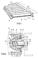
- a section of roller decking is indicated by the reference numeral 10, and the decking will be seen to comprise side rails 12 and 14 of channel sectioned angle iron forming part of the decking frame, between which extend a plurality of parallel, spaced and freely rotatable rollers 16.
- the decking illustrated is of the gravity type insofar as the plane which contains the rollers (which are identical) is inclined, so that articles 18 to be transported by the roller decking in fact move down the decking under gravity, turning the rollers about their axes as the articles proceed.
- the present invention is concerned with the rolling bearings which are located at the ends of the rollers 16 and enable each roller to rotate about its axis, and therefore reference is now made to Fig. 2 which shows one of these bearings in sectional elevation.
- the bearing at the other end of the roller is of identical construction.
- the roller 16 comprises a sleeve 20 of stainless steel or plastics, and the rolling bearing 22 is simply a push-fit in the end of the sleeve 20.
- the rolling bearing 22 comprises an outer bearing race 24, and an inner bearing race 26.
- the outer bearing race 24 is in the form of a cup 28 which blanks off the interior of the sleeve 20 from the surrounding atmosphere. This prevents the ingress of any moisture or other material into the interior of the sleeve 20 which could subsequently form a bacteria trap, and the prevention of such ingress is a significant advantage of the present invention.
- the cup 28 has a blind cavity which is of increasing cross section from the base to the open end of the cup (28) with no undercuts except for the race track (34) which receives the rolling elements (36).
- the outer race 24 is provided with a cylindrical outer portion 30 having at one end a flange 32 which abuts against the end of the sleeve into which the bearing 22 is inserted as shown in Fig. 2.
- the outer bearing race 24 is also formed with a bearing race track 34 on which the rolling elements of the rolling bearing run, said elements 36 being held in equiangularly arranged relationship by means of a cage 38 of the rolling bearing which is of conventional construction and is preferably formed in plastics material.
- the rolling bearing elements 36 are steel balls.
- the inner bearing race 40 is also in the form of a closed cup 42, the central recess of same forming a bore 44 in which is received a support spindle 46 of stainless steel which is in fact secured to the adjacent side rail by means of a nut 48.
- a compression spring 50 which reacts against the base of the bore 44 and at the end of the spindle 46 thereby effecting a resilient support for the roller 16 when in use, it being borne in mind that there is a similar mounting arrangement at the opposite end of the roller.
- the race is provided with a covering flange portion 50A which extends outward to the outer race as shown so that only a small gap 52 exists between the outer and inner races limiting the extent to which moisture and other material may enter the rolling bearing, there is an unrestricted path for water which flows into the bearing through the same gap 52 at the top of the bearing to draw from the bearing through the same gap at the bottom of the bearing passing the balls 34 as it flows into the bearing and as it flows out of same.
- a forwardly projecting portion 54 of the inner race 40 is provided on opposite sides with flats so that it may be engaged by means of an appropriately dimensioned spanner and can be held from rotation whilst the nut 48 on the spindle is being tightened in order to tighten the nut to secure the spindle to the side rail 14.
- the spindle 46 and the bore 44 of the inner race preferably are non-circular.
- the inner race also has a race track 51 for the balls 36.
- the outer race 24 in effect provides a complete seal for the interior of the sleeve 20, preventing the formation of bacteria therein and indeed the formation of corrosive spots.
- the rolling bearings being essentially of plastics material, may be manufactured relatively inexpensively, and if need be can readily be removed and replaced. This is preferable to replacing the roller sleeve especially where such sleeve is of stainless steel.
Landscapes
- Engineering & Computer Science (AREA)
- General Engineering & Computer Science (AREA)
- Mechanical Engineering (AREA)
- Rolling Contact Bearings (AREA)
- Packaging Of Annular Or Rod-Shaped Articles, Wearing Apparel, Cassettes, Or The Like (AREA)
- Rolls And Other Rotary Bodies (AREA)
- Detail Structures Of Washing Machines And Dryers (AREA)
- Rollers For Roller Conveyors For Transfer (AREA)
- Sealing Battery Cases Or Jackets (AREA)
Claims (5)
- Un palier à roulements, convenant à un rouleau ou un agencement à rouleaux (10), comprenant des voies interne et externe (24, 26) avec, entre ces deux, des éléments de roulement (34), la voie externe (24) se présentant sous la forme d'une cuvette d'obturation (24) avec une cavité borgne, cette cuvette pouvant être montée dans l'extrémité d'un manchon (20) et la voie interne (26) étant munie d'un arbre de montage (46) ou agencée pour être raccordée à un arbre de montage, qui se prolonge à partir de l'extrémité du manchon (20) dans lequel le palier à roulements (22) est censé se loger, caractérisé en ce que la cavité borgne de la cuvette d'obturation a une section transversale croissante à partir de la base jusqu'à l'extrémité ouverte de la cuvette (28) sans contre-dépouille à l'exception d'une voie de roulement (34) qui reçoit les éléments de roulement.
- Un palier, selon les stipulations de la revendication 1, caractérisé en ce que la voie interne (26) se présente sous la forme d'une cuvette (40) qui est munie d'un alésage central destiné à recevoir ledit arbre (46).
- Un palier, selon les stipulations de la revendication 2, caractérisé en ce que le fond dudit alésage pour l'arbre (46) reçoit un ressort (18), cas dans lequel, quand deux de ces paliers (22) sont utilisés en tant que support pour un rouleau (16) dans un agencement à rouleaux (10), le rouleau pourra alors se déplacer contre l'action du ressort lors de d'enlèvement du rouleau (16) de l'agencement à rouleaux, à des fins de remplacement et de réparation.
- Un palier, selon les stipulations de la revendication 1, 2 ou 3, caractérisé en ce que les voies interne et externe (24, 26) sont fabriquées en plastique moulé, usinées le cas échéant, et les éléments de roulement sont des billes en acier agencées selon une relation équi-angulaire autour de l'axe du palier, et maintenues dans cet état au moyen d'une cage de palier à rouleaux en plastique.
- Un palier, selon les stipulations de l'une quelconque des revendications précédentes, caractérisé en ce que la voie interne (26) est munie de méplats qui permettent de la maintenir avec une clé, tout en maintenant ledit arbre de montage et pendant qu'il est en train d'être immobilisé par un écrou (48) pour le fixer sur un bâti de support (12, 14).
Applications Claiming Priority (3)
| Application Number | Priority Date | Filing Date | Title |
|---|---|---|---|
| GB919100772A GB9100772D0 (en) | 1991-01-15 | 1991-01-15 | Improvements relating to bearings for rollers and the like |
| GB9100772 | 1991-01-15 | ||
| PCT/GB1992/000070 WO1992013204A1 (fr) | 1991-01-15 | 1992-01-14 | Ameliorations relatives aux roulement pour rouleaux et analogues |
Publications (2)
| Publication Number | Publication Date |
|---|---|
| EP0566627A1 EP0566627A1 (fr) | 1993-10-27 |
| EP0566627B1 true EP0566627B1 (fr) | 1995-07-05 |
Family
ID=10688414
Family Applications (1)
| Application Number | Title | Priority Date | Filing Date |
|---|---|---|---|
| EP92902713A Expired - Lifetime EP0566627B1 (fr) | 1991-01-15 | 1992-01-14 | Ameliorations relatives aux roulement pour rouleaux et analogues |
Country Status (7)
| Country | Link |
|---|---|
| US (1) | US5380104A (fr) |
| EP (1) | EP0566627B1 (fr) |
| AT (1) | ATE124760T1 (fr) |
| CA (1) | CA2099244C (fr) |
| DE (1) | DE69203340D1 (fr) |
| GB (1) | GB9100772D0 (fr) |
| WO (1) | WO1992013204A1 (fr) |
Families Citing this family (11)
| Publication number | Priority date | Publication date | Assignee | Title |
|---|---|---|---|---|
| WO1995019309A1 (fr) * | 1992-07-08 | 1995-07-20 | Bnl Limited | Ameliorations apportees a des paliers pour rouleaux et autres elements similaires |
| US6076647A (en) | 1997-09-29 | 2000-06-20 | Interroll Holding Ag | Stub shaft conveyor roller |
| AUPQ703400A0 (en) * | 2000-04-19 | 2000-05-18 | Jlv Industries Pty Ltd | Conveyor roller bearing housing |
| AUPQ703500A0 (en) * | 2000-04-19 | 2000-05-18 | Jlv Industries Pty Ltd | Bearing housing and roller shaft seal |
| US6772873B1 (en) * | 2001-10-22 | 2004-08-10 | Dillin Engineered Systems Corporation | Drive system for roller conveyor |
| US6782996B1 (en) * | 2003-02-13 | 2004-08-31 | Rapistan Systems Advertising Corp. | Axle cartridge for conveyor roller |
| US20070261933A1 (en) * | 2006-04-26 | 2007-11-15 | Scott C W | Conveyor roller assembly and conveyor roller insert |
| US8881884B2 (en) * | 2011-12-02 | 2014-11-11 | Michael Richard Kaminski, Jr. | Rebuildable roller and roller bearing assembly for a belt line conveyor system and a method of use thereof |
| WO2014004453A1 (fr) | 2012-06-29 | 2014-01-03 | The Procter & Gamble Company | Système et procédé pour l'application continue à grande vitesse d'un matériau de bande sur un matériau de substrat mobile du type feuille |
| US9868606B2 (en) * | 2012-06-29 | 2018-01-16 | The Proctor & Gamble Company | Rotary drum apparatus reconfigurable for various size substrates |
| US10472179B2 (en) | 2017-03-09 | 2019-11-12 | Lewco, Inc. | Cartridge bearing assembly for roller conveyors |
Family Cites Families (6)
| Publication number | Priority date | Publication date | Assignee | Title |
|---|---|---|---|---|
| US1362910A (en) * | 1919-01-27 | 1920-12-21 | Buzz Engineering Company | Conveyer-roller |
| US2190336A (en) * | 1936-06-22 | 1940-02-13 | Olson Samuel | Conveyer roller construction |
| GB2059012B (en) * | 1979-09-07 | 1983-01-19 | Garnett D M | Conveyor rollers |
| FR2496610A1 (fr) * | 1980-12-20 | 1982-06-25 | Mannesmann Ag | Rouleau porteur pour convoyeur |
| US4606659A (en) * | 1985-04-01 | 1986-08-19 | General Motors Corporation | Bearing and stub shaft assembly |
| EP0432311A1 (fr) * | 1989-12-15 | 1991-06-19 | ERBÖ-MASCHINENBAU ERLEY & BÖNNINGER GMBH & CO. KG | Rouleau porteur pour convoyeur à bande |
-
1991
- 1991-01-15 GB GB919100772A patent/GB9100772D0/en active Pending
-
1992
- 1992-01-14 CA CA002099244A patent/CA2099244C/fr not_active Expired - Fee Related
- 1992-01-14 US US08/087,689 patent/US5380104A/en not_active Expired - Fee Related
- 1992-01-14 DE DE69203340T patent/DE69203340D1/de not_active Expired - Lifetime
- 1992-01-14 EP EP92902713A patent/EP0566627B1/fr not_active Expired - Lifetime
- 1992-01-14 AT AT92902713T patent/ATE124760T1/de not_active IP Right Cessation
- 1992-01-14 WO PCT/GB1992/000070 patent/WO1992013204A1/fr not_active Ceased
Also Published As
| Publication number | Publication date |
|---|---|
| WO1992013204A1 (fr) | 1992-08-06 |
| GB9100772D0 (en) | 1991-02-27 |
| ATE124760T1 (de) | 1995-07-15 |
| CA2099244C (fr) | 2002-08-20 |
| EP0566627A1 (fr) | 1993-10-27 |
| DE69203340D1 (de) | 1995-08-10 |
| US5380104A (en) | 1995-01-10 |
| CA2099244A1 (fr) | 1992-07-16 |
Similar Documents
| Publication | Publication Date | Title |
|---|---|---|
| EP0566627B1 (fr) | Ameliorations relatives aux roulement pour rouleaux et analogues | |
| US4681215A (en) | Conveyor roller and bearing assembly with external support | |
| US3971601A (en) | Sanitary anti-friction trolley wheel | |
| US4433627A (en) | Plastic conveyor trolley with bearings | |
| EP0112026A1 (fr) | Rouleau d'appui pour convoyeur | |
| US4645071A (en) | Idler roll assembly | |
| US9482281B2 (en) | Removable bearing cover | |
| EP0426505B1 (fr) | Appareil pour transporter des céréales | |
| EP0059270A1 (fr) | Assemblages de paliers pour rouleaux de transport | |
| US4325473A (en) | Bearing assemblies for use in conveyor roller | |
| US4345678A (en) | Roller conveyors | |
| US4858752A (en) | Wheel assembly for conveyer system | |
| US4685556A (en) | Drive mechanism for a live roller conveyor | |
| US7775162B1 (en) | Roller for trolley assembly | |
| US3648824A (en) | Idler roller device for troughed conveyor belts | |
| US4326619A (en) | Relating to bearing assemblies for use in conveyor rollers | |
| US4844241A (en) | Conveyor stub idler roll apparatus | |
| US1541410A (en) | Conveyer | |
| US4830179A (en) | Idler rollers for belt conveyors | |
| GB2059012A (en) | Conveyor rollers | |
| GB2269637A (en) | Bearing and stub shaft assembly. | |
| EP0121021A1 (fr) | Rouleau transporteur | |
| WO1995019309A1 (fr) | Ameliorations apportees a des paliers pour rouleaux et autres elements similaires | |
| KR101956477B1 (ko) | 컨베이어용 프릭션 롤러 | |
| GB2058957A (en) | Improvements relating to bearing assemblies for use in conveyor rollers |
Legal Events
| Date | Code | Title | Description |
|---|---|---|---|
| PUAI | Public reference made under article 153(3) epc to a published international application that has entered the european phase |
Free format text: ORIGINAL CODE: 0009012 |
|
| 17P | Request for examination filed |
Effective date: 19930618 |
|
| AK | Designated contracting states |
Kind code of ref document: A1 Designated state(s): AT BE CH DE DK ES FR GB GR IT LI LU NL SE |
|
| 17Q | First examination report despatched |
Effective date: 19940609 |
|
| GRAA | (expected) grant |
Free format text: ORIGINAL CODE: 0009210 |
|
| AK | Designated contracting states |
Kind code of ref document: B1 Designated state(s): AT BE CH DE DK ES FR GB GR IT LI LU NL SE |
|
| PG25 | Lapsed in a contracting state [announced via postgrant information from national office to epo] |
Ref country code: NL Free format text: LAPSE BECAUSE OF FAILURE TO SUBMIT A TRANSLATION OF THE DESCRIPTION OR TO PAY THE FEE WITHIN THE PRESCRIBED TIME-LIMIT Effective date: 19950705 Ref country code: LI Effective date: 19950705 Ref country code: IT Free format text: LAPSE BECAUSE OF FAILURE TO SUBMIT A TRANSLATION OF THE DESCRIPTION OR TO PAY THE FEE WITHIN THE PRE;WARNING: LAPSES OF ITALIAN PATENTS WITH EFFECTIVE DATE BEFORE 2007 MAY HAVE OCCURRED AT ANY TIME BEFORE 2007. THE CORRECT EFFECTIVE DATE MAY BE DIFFERENT FROM THE ONE RECORDED.SCRIBED TIME-LIMIT Effective date: 19950705 Ref country code: GR Free format text: LAPSE BECAUSE OF FAILURE TO SUBMIT A TRANSLATION OF THE DESCRIPTION OR TO PAY THE FEE WITHIN THE PRESCRIBED TIME-LIMIT Effective date: 19950705 Ref country code: FR Effective date: 19950705 Ref country code: ES Free format text: THE PATENT HAS BEEN ANNULLED BY A DECISION OF A NATIONAL AUTHORITY Effective date: 19950705 Ref country code: DK Effective date: 19950705 Ref country code: CH Effective date: 19950705 Ref country code: BE Effective date: 19950705 Ref country code: AT Effective date: 19950705 |
|
| REF | Corresponds to: |
Ref document number: 124760 Country of ref document: AT Date of ref document: 19950715 Kind code of ref document: T |
|
| REF | Corresponds to: |
Ref document number: 69203340 Country of ref document: DE Date of ref document: 19950810 |
|
| PG25 | Lapsed in a contracting state [announced via postgrant information from national office to epo] |
Ref country code: SE Effective date: 19951005 |
|
| PG25 | Lapsed in a contracting state [announced via postgrant information from national office to epo] |
Ref country code: DE Effective date: 19951006 |
|
| REG | Reference to a national code |
Ref country code: CH Ref legal event code: PL |
|
| EN | Fr: translation not filed | ||
| NLV1 | Nl: lapsed or annulled due to failure to fulfill the requirements of art. 29p and 29m of the patents act | ||
| PG25 | Lapsed in a contracting state [announced via postgrant information from national office to epo] |
Ref country code: LU Free format text: LAPSE BECAUSE OF NON-PAYMENT OF DUE FEES Effective date: 19960131 |
|
| PLBE | No opposition filed within time limit |
Free format text: ORIGINAL CODE: 0009261 |
|
| STAA | Information on the status of an ep patent application or granted ep patent |
Free format text: STATUS: NO OPPOSITION FILED WITHIN TIME LIMIT |
|
| 26N | No opposition filed | ||
| REG | Reference to a national code |
Ref country code: GB Ref legal event code: IF02 |
|
| PGFP | Annual fee paid to national office [announced via postgrant information from national office to epo] |
Ref country code: GB Payment date: 20051205 Year of fee payment: 15 |
|
| GBPC | Gb: european patent ceased through non-payment of renewal fee |
Effective date: 20070114 |
|
| PG25 | Lapsed in a contracting state [announced via postgrant information from national office to epo] |
Ref country code: GB Free format text: LAPSE BECAUSE OF NON-PAYMENT OF DUE FEES Effective date: 20070114 |