EP0566802A1 - Dispositif de préparation de mais éclaté - Google Patents
Dispositif de préparation de mais éclaté Download PDFInfo
- Publication number
- EP0566802A1 EP0566802A1 EP92401017A EP92401017A EP0566802A1 EP 0566802 A1 EP0566802 A1 EP 0566802A1 EP 92401017 A EP92401017 A EP 92401017A EP 92401017 A EP92401017 A EP 92401017A EP 0566802 A1 EP0566802 A1 EP 0566802A1
- Authority
- EP
- European Patent Office
- Prior art keywords
- box
- bottom wall
- corn
- popcorn
- wall
- Prior art date
- Legal status (The legal status is an assumption and is not a legal conclusion. Google has not performed a legal analysis and makes no representation as to the accuracy of the status listed.)
- Withdrawn
Links
- 235000002017 Zea mays subsp mays Nutrition 0.000 title claims abstract description 45
- 241000482268 Zea mays subsp. mays Species 0.000 title claims abstract description 20
- 235000005824 Zea mays ssp. parviglumis Nutrition 0.000 claims abstract description 26
- 235000005822 corn Nutrition 0.000 claims abstract description 26
- 240000008042 Zea mays Species 0.000 claims description 25
- 230000009172 bursting Effects 0.000 claims description 3
- 230000001154 acute effect Effects 0.000 claims description 2
- 235000019640 taste Nutrition 0.000 description 4
- 238000010411 cooking Methods 0.000 description 3
- 238000009826 distribution Methods 0.000 description 3
- 238000010438 heat treatment Methods 0.000 description 2
- 238000004519 manufacturing process Methods 0.000 description 2
- 238000002360 preparation method Methods 0.000 description 2
- 210000002105 tongue Anatomy 0.000 description 2
- 238000007664 blowing Methods 0.000 description 1
- 230000005465 channeling Effects 0.000 description 1
- 230000009849 deactivation Effects 0.000 description 1
- 238000006073 displacement reaction Methods 0.000 description 1
- 239000002184 metal Substances 0.000 description 1
- 238000000034 method Methods 0.000 description 1
- 238000003825 pressing Methods 0.000 description 1
- 238000004064 recycling Methods 0.000 description 1
- 239000011435 rock Substances 0.000 description 1
- 238000005096 rolling process Methods 0.000 description 1
- 239000000523 sample Substances 0.000 description 1
- 238000009423 ventilation Methods 0.000 description 1
Images

Classifications
-
- G—PHYSICS
- G07—CHECKING-DEVICES
- G07F—COIN-FREED OR LIKE APPARATUS
- G07F17/00—Coin-freed apparatus for hiring articles; Coin-freed facilities or services
- G07F17/0064—Coin-freed apparatus for hiring articles; Coin-freed facilities or services for processing of food articles
- G07F17/0078—Food articles which need to be processed for dispensing in a hot or cooked condition, e.g. popcorn, nuts
- G07F17/0085—Food articles which for processing need cooking in a liquid, e.g. oil, water
-
- A—HUMAN NECESSITIES
- A23—FOODS OR FOODSTUFFS; TREATMENT THEREOF, NOT COVERED BY OTHER CLASSES
- A23L—FOODS, FOODSTUFFS OR NON-ALCOHOLIC BEVERAGES, NOT OTHERWISE PROVIDED FOR; PREPARATION OR TREATMENT THEREOF
- A23L7/00—Cereal-derived products; Malt products; Preparation or treatment thereof
- A23L7/10—Cereal-derived products
- A23L7/161—Puffed cereals, e.g. popcorn or puffed rice
- A23L7/174—Preparation of puffed cereals from wholegrain or grain pieces without preparation of meal or dough
- A23L7/183—Preparation of puffed cereals from wholegrain or grain pieces without preparation of meal or dough by heating without using a pressure release device
- A23L7/187—Discontinuously-working apparatus
-
- G—PHYSICS
- G07—CHECKING-DEVICES
- G07F—COIN-FREED OR LIKE APPARATUS
- G07F17/00—Coin-freed apparatus for hiring articles; Coin-freed facilities or services
- G07F17/0064—Coin-freed apparatus for hiring articles; Coin-freed facilities or services for processing of food articles
- G07F17/0078—Food articles which need to be processed for dispensing in a hot or cooked condition, e.g. popcorn, nuts
Definitions
- the invention relates to the production of popcorn, or popcorn.
- a device for preparing popcorn comprising a bursting chamber, a means for introducing hot air to the lower part of the chamber and a means to introduce corn at the top.
- the known device can give satisfaction for the preparation of portions of popcorn in a domestic setting, but cannot be suitable for the distribution of popcorn in vending machines intended for the public. Indeed, the known apparatus requires manual loading of the popped corn for each dose of prepared corn; moreover, the popped corn is in a tank which must be overturned manually to empty it.
- the ultimate aim of the invention is to propose a popcorn dispensing machine and, to do this, a first step is to propose a preparation device compatible with this aim.
- the subject of the invention is a device for preparing popped corn, the popping chamber of which is in the form of a box of substantially triangular shape having a substantially horizontal upper wall, a substantially vertical front wall, two cheeks substantially vertical sides, and an oblique and movable bottom wall, capable of occupying a closed position of the box for the achievement of the burst and an open position for the payment of a load of popcorn.
- the bottom wall is articulated near the acute upper corner of the box.
- Two pipe flanges adjacent to the box flanges can be associated, integral, with the bottom wall.
- the bottom wall is bent.
- the box is supplied with corn via at least one corn metering volume.
- corn metering volume Several dosing volumes provide several kinds or tastes of corn.
- the bottom wall is advantageously associated with a mechanism for filling the metering volume (s), whereby the opening of the bottom wall, at the end of each bursting cycle, automatically fills the empty metering volume which has last served.
- the metering volume or volumes are associated with a selective emptying mechanism, linked to the choice made by the consumer of the type of corn.
- the bottom wall of the box is capable of pouring the charge of popcorn into a cup put in place by a dispenser of cups.
- the cup dispenser is that described in French application No. 90 11 970 to the Applicant, the teaching of which is incorporated here by reference.
- the cup overturning system described in this application is ideally integrated into the device according to the present invention, in particular thanks to the oblique bottom wall which leaves the space necessary for housing the overturning system, this wall of bottom may even constitute a pipe wall of the overturning system. Thanks to this arrangement, a particularly compact machine is obtained.
- the device of the invention is preferably integrated into a coin dispensing machine, possibly associated with a lottery device.
- the machine 1 for dispensing the popcorn takes on a generally attractive shape, for example that of a stylized character, with his feet and his hands.
- the body in fact conceals two compartments respectively lower 2 and upper 3.
- the lower compartment 2 is accessible from the front by a tilting door 4 and contains typically the cup and revolving barrel magazine described in French application n ° 90 11 970.
- the electronic part of the device is fixed on a plate itself mounted inside the tilting door 4 and easy to access.
- the upper compartment 3 contains a set of devices mounted on rails so as to be able to be extracted forward, integrally with the front panel 4. This includes a light animation 5, the slot 6 of a coin mechanism, the lever 7 of a lottery, all kinds of indicators 8 concerning the indication of deactivation, the results of the lottery and information on the progress of the process, buttons 9 for selecting the type (taste) of popcorn chosen , an opening 10 at hand level to remove a cup filled with the portion of corn, windows 11 for viewing the interior of the cooker to see the corn popping during cooking.
- a lock 12 makes it possible to lock and unlock the upper compartment, itself controlling the opening of the lower compartment.
- the open upper compartment 3 reveals the fan 31 of the cooker which will now be described.
- the system according to the invention comprises a cooker-blower 20 supplied by a distributor 50.
- the cooker 20 is produced in the form of a substantially triangular metal box 24, having a horizontal upper wall 21, a vertical front wall 22, and two horizontal lateral cheeks 23. These walls are fixed while a bottom diagonal wall 25 closing the box is mounted articulated around a horizontal axis 26 placed near the upper corner of the box, so that the bottom wall 25 can move between a closed position, as shown in solid lines in FIG. 3, and the open position and payment sketched in dotted lines under the reference. 25 '.
- the wall 25 includes the attachment 26 of a connecting rod 27 connected to conventional motor means not shown allowing passage from one position to the other, on command.
- the wall 25 is curved towards the inside of the box by forming a folding angle 28 and comprises two vertical cheeks 29 forming a pouring assembly.
- the movable vertical cheeks 29 are substantially tangent to the fixed cheeks 23 of the cooker. They allow a good channeling of the popped corn during the emptying, avoid risks of inadvertent opening of the bottom wall during the popping, and also make it possible to avoid the jamming of corn which would prevent a good reclosing of the wall of the background.
- the lower corner of the box is occupied by a blowing pipe 30 connected to a blower 31 equipped with a heating resistor 32 and housed against one of the cheeks 23 of the box.
- Line 30 sends the hot air into the box through an inclined grid 33.
- a probe 34 connected to a regulator 35 itself connected (by connections not shown) to the resistor 32 makes it possible to control the temperature of the forced air sent to the cooker.
- the front front wall 22 of the box has an orifice 36 covered by a window 37 allowing the interior of the box to be seen.
- the upper wall 21 of the box has, near its upper corner, an opening 38, provided with a grid 39, for the evacuation of the air blown by a chimney 40. It is possible to provide for recycling, in all or part, of the heating air by means of a thermally insulated recirculation line 40 ′ pricked on the chimney 40 and returning the air to the fan 31. Inside the chimney 40, a hatch (not shown) adjustable allows to deflect at will all or part of the air used.
- the upper wall 21 also has two openings 41 communicating with the respective distribution channels of the distributor 50 (two in the case shown).
- the popcorn dispenser comprises hoppers 41 in number equal to the types of corn distributed (here two; a single hopper is visible in Figure 3, because they are placed one behind the other).
- each hopper 51 communicates with vertical dosing tubes 52, disposed below the openings 41 of the cooker.
- the metering tubes 52 are produced in the form of separate parts from the hoppers 51, so that they can be more easily changed if the dose to be dispensed has to be greatly modified.
- the tubes 52 have at their upper part a wide slot 53 extending practically over a half-circumference so as to allow a movable horizontal obturator tongue 54 to pass.
- the two coplanar tongues 54 are formed in the same piece 55 in the form of a plate to which is fixed, at 56, a control linkage 57.
- This linkage 57 articulated at 56 is articulated at its other end on an arm 58 secured to the bottom wall 25, so that the opening of the wall 25 in the direction of the arrow 59 causes the horizontal displacement of the plate 55 so that the shutter tabs 54 retract and release the communication of the metering tubes 52 with the hoppers 51.
- the reverse movement of the bottom wall 25 causes this communication to be closed.
- the lower part of the dosing tubes 52 is closed, in a removable manner, by a disc or plate 60 carried by an adjustable foot 61 (by screwing for example) secured to a tilting valve 62.
- the valve 62 rocks around a horizontal axis 63 and is secured to an arm 64 biased on one side towards a stop position of the valve 62 by a spring 65 hung on a fixed wall 66 and on the other side by a rod 67 whose movement is controlled by an electromagnet.
- the disc 60 which has a large clearance with the walls of the tube 52 makes it possible to avoid jamming of grains of corn with the valve 62, which would not fail to happen in the absence of the disc.
- the hoppers 51 can then be filled in the upper part with corn of different type, and the money can be collected from the coin box.
- cup magazine for example 200 cups.
- the bottom 25 opens, empty, and the metering tubes 52 are filled.
- a speed camera can detect a consumer passing by; the sound animation starts.
- the consumer introduces a coin into the coin mechanism - the music changes and instructs the consumer on how a lottery works.
- the light animation is total and fixed. Only a flashing light indicates that the handle 7 must be lowered.
- the consumer lowers the lottery lever 7 which triggers the distribution of a cup in the compartment 10 protected by a hatch.
- the light animation becomes revolving again.
- the consumer chooses from the tastes that are offered, the one that suits him, by pressing the buttons at his disposal.
- the two dosing tubes 52 are full.
- the fan 31 and the heater 32 are started; a few moments later, one of the valves 62 opens a few seconds following the selection of the consumer controlled by one of the electromagnets 68.
- the corn falls on the grid 33 and is stirred in the air heated to constant temperature.
- the air temperature, the air flow rate, the shape of the lower part 25 'of the bottom 25 and the cooking time mean that maximum expansion and an ideal taste of the cooked corn are obtained.
- the angled shape of the bottom 25 makes it possible to establish above the grid 33 a column of corn balanced with respect to the ventilation pressure.
- the slope of the 25 'part (which is not intentionally vertical) favors the rolling of the corn.
- the volume formed between the part 25 ′, the side cheeks and the front wall 22 makes it possible to receive the quantity of corn to be expanded.
- the fan 31 and the heater 32 stop. A few moments later, the bottom 25 opens, controlled by a motor not shown. The residue of blast through the grid 33 is sufficient to clear the latter of any trace of corn. The cheeks 29 correctly channel the popcorn towards the opening of a waiting cup located just below. The dosing tubes 52 are again filled, the link 58 actuating the pull tab 57. In the event that the lottery is winning, the machine sings it; a light animation anarchic appears; a warning light signals it.
Landscapes
- Life Sciences & Earth Sciences (AREA)
- Engineering & Computer Science (AREA)
- Food Science & Technology (AREA)
- Physics & Mathematics (AREA)
- General Physics & Mathematics (AREA)
- Health & Medical Sciences (AREA)
- Nutrition Science (AREA)
- Chemical & Material Sciences (AREA)
- Polymers & Plastics (AREA)
- Vending Machines For Individual Products (AREA)
- Grain Derivatives (AREA)
Abstract
Le dispositif, équipant un distributeur à pièces, comprend : une chambre d'éclatement réalisée sous forme d'un caisson (24) de forme triangulaire possédant une paroi supérieure (21) horizontale, une paroi frontale (22) verticale, deux joues latérales (23) verticales, et une paroi de fond (25) oblique articulée susceptible de fermer le caisson (24) pour l'éclatement et de s'ouvrir pour verser une charge de maïs éclaté dans un gobelet; un moyen (30) pour introduire de l'air chaud à sa partie inférieure; et des moyens (41) pour introduire du maïs à sa partie supérieure.
Description
- L'invention concerne la fabrication du maïs éclaté, ou pop-corn.
- On connaît par exemple, par le document US-A-4 178 843, un dispositif de préparation du pop-corn comportant une chambre d'éclatement, un moyen pour introduire de l'air chaud à la partie inférieure de la chambre et un moyen pour introduire du maïs à sa partie supérieure.
- L'appareil connu peut donner satisfaction pour la préparation de portions de maïs éclaté dans un cadre domestique, mais ne saurait convenir à la distribution de pop-corn dans des machines distributrices destinées au public. En effet, l'appareil connu impose un chargement manuel du maïs non éclaté pour chaque dose de maïs préparée; de plus, le maïs éclaté se trouve dans une cuve qu'il faut renverser manuellement pour la vider.
- Le but ultime de l'invention est de proposer une machine distributrice de pop-corn et, pour ce faire, une première étape est de proposer un dispositif de préparation compatible avec ce but.
- A cette fin, l'invention a pour objet un dispositif de préparation de maïs éclaté dont la chambre d'éclatement est réalisée sous forme d'un caisson de forme sensiblement triangulaire possédant une paroi supérieure sensiblement horizontale, une paroi frontale sensiblement verticale, deux joues latérales sensiblement verticales, et une paroi de fond oblique et mobile, susceptible d'occuper une position de fermeture du caisson pour la réalisation de l'éclatement et une position d'ouverture pour le versement d'une charge de maïs éclaté.
- Grâce à ces dispositions, il est possible de préparer successivement plusieurs charges de maïs éclaté qu'on peut facilement verser, à la fin de chaque cycle d'éclatement, dans un récipient prévu à cet effet sous le caisson, et plus précisément sous la zone d'ouverture de la paroi de fond mobile.
- Avantageusement, la paroi de fond est articulée près du coin supérieur aigu du caisson. Deux joues de canalisation adjacentes aux joues du caisson peuvent être associées, solidaires, à la paroi de fond.
- Avantageusement, la paroi de fond est coudée.
- De préférence, le caisson est alimenté en maïs par l'intermédiaire d'au moins un volume doseur de maïs. Plusieurs volumes doseurs permettent de disposer de plusieurs sortes ou goûts de maïs.
- La paroi du fond est avantsgeusement associée à un mécanisme de remplissage du ou des volumes doseurs, grâce à quoi l'ouverture de la paroi de fond, à la fin de chaque cycle d'éclatement, entraîne automatiquement le remplissage du volume doseur vide qui a servi en dernier lieu. Le ou les volumes doseurs sont associés à un mécanisme de vidange sélectif, lié au choix fait par le consommateur du type de maïs.
- Selon une caractéristique préférée, la paroi de fond du caisson est susceptible de verser la charge de maïs éclaté dans un gobelet mis en place par un dis tributeur de gobelets.
- De manière tout particulièrement avantageuse, le distributeur de gobelets est celui qui est décrit dans la demande française n° 90 11 970 du Demandeur dont on incorpore ici l'enseignement par référence. En effet, le système de renversement de gobelet décrit dans cette demande s'intègre de manière idéale au dispositif conforme à la présente invention, notamment grâce à la paroi de fond oblique qui laisse la place nécessaire au logement du système de renversement, cette paroi de fond pouvant même constituer une paroi de canalisation du système de renversement. On obtient grâce à cette disposition une machine particulièrement compacte.
- Enfin, le dispositif de l'invention s'intègre de préférence dans une machine de distribution à pièces, éventuellement associée à un dispositif de loterie.
- D'autres caractéristiques et avantages apparaîtront à la lecture de la description suivante qui sera faite d'un mode de réalisation. On se référera aux dessins annexés sur lesquels :
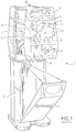
- la figure 1 est une vue en perspective de la machine, les compartiments du haut et du bas étant ouverts.
- La figure 2 est une vue en coupe schématique frontale du cuiseur et du distributeur.
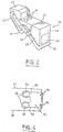
- La figure 3 est une vue en perspective schématique du cuiseur.
- La figure 4 est une vue schématique en coupe horizontale du système d'obturation supérieure des tubes doseurs, du distributeur.
- La machine 1 à distribuer le pop-corn revêt une forme générale attrayante, par exemple celle d'un personnage stylisé, avec ses pieds et ses mains. Le corps cache en fait deux compartiments respectivement inférieur 2 et supérieur 3. Le compartiment inférieur 2 est accessible par l'avant grâce à une porte basculante 4 et contient typiquement le magasin à gobelets et barillet tournant décrit dans la demande française n° 90 11 970. La partie électronique de l'appareil est fixée sur une platine elle-même montée à l'intérieur de la porte basculante 4 et facile d'accès.
- Le compartiment supérieur 3 renferme un ensemble de dispositifs montés sur rails de manière à pouvoir s'extraire vers l'avant, solidairement de la façade avant 4. Celle-ci comporte une animation lumineuse 5, la fente 6 d'un monnayeur, le levier 7 d'une loterie, toutes sortes de voyants 8 concernant l'indication de mise hors-service, les résultats de la loterie et des informations sur le déroulement du procédé, des boutons 9 de sélection du type (goût) de pop-corn choisi, une ouverture 10 à hauteur de main pour retirer un gobelet rempli de la portion de maïs, des fenêtres 11 de vision de l'intérieur du cuiseur pour voir éclater le maïs pendant la cuisson. Sur le dessus du compartiment, une serrure 12 permet de verrouiller et déverouiller le compartiment supérieur, commandant lui-même l'ouverture du compartiment inférieur.
- Le compartiment supérieur 3 ouvert laisse apparaître le ventilateur 31 du cuiseur qui va maintenant être décrit.
- Le système conforme à l'invention comprend un cuiseur-souffleur 20 alimenté par un distributeur 50.
- Le cuiseur 20 est réalisé sous forme d'un caisson métallique 24 sensiblement triangulaire, présentant une paroi supérieure 21 horizontale, une paroi frontale verticale 22, et deux joues latérales horizontales 23. Ces parois sont fixes tandis qu'une paroi diagonale de fond 25 fermant le caisson est montée articulée autour d'un axe horizontal 26 placé près du coin supérieur du caisson, de sorte que la paroi de fond 25 peut se déplacer entre une position de fermeture, telle que représentée en traits pleins sur la figure 3, et la position d'ouverture et de versement esquissée en pointillés sous la référence. 25'. La paroi 25 comporte l'attache 26 d'une bielle 27 reliée à des moyens moteurs classiques non représentés permettant le passage d'une position à l'autre, sur commande.
- La paroi 25 est cintrée vers l'intérieur du caisson en formant un angle de pliage 28 et comporte deux joues verticales 29 formant un ensemble verseur. Les joues verticales 29 mobiles sont sensiblement tangentes aux joues fixes 23 du cuiseur. Elles permettent une bonne canalisation du maïs éclaté lors de la vidange, évitent des risques d'ouverture intempestive de la paroi du fond lors de l'éclatement, et permettent aussi d'éviter le coincement de maïs qui empêcherait une bonne refermeture de la paroi du fond.
- Le coin inférieur du caisson est occupé par une conduite de soufflage 30 reliée à un souffleur 31 équipé d'une résistance chauffante 32 et logé contre l'une des joues 23 du caisson. La conduite 30 envoie l'air chaud dans le caisson au travers d'une grille 33 inclinée. Une sonde 34 reliée à un régulateur 35 lui-même relié (par des connexions non représentées) à la résistance 32 permet de commander la température de l'air pulsé envoyé dans le cuiseur.
- La paroi frontale avant 22 du caisson comporte un orifice 36 recouvert par une vitre 37 permettant de voir l'intérieur du caisson.
- La paroi supérieure 21 du caisson comporte, près de son coin supérieur, une ouverture 38, munie d'une grille 39, pour l'évacuation de l'air soufflé par une cheminée 40. Il est possible de prévoir un recyclage, en tout ou partie, de l'air de chauffe au moyen d'une conduite de recirculation thermiquement isolée 40' piquée sur la cheminée 40 et renvoyant l'air vers le ventilateur 31. A l'intérieur de la cheminée 40, une trappe (non représentée) réglable permet de dévier à volonté tout ou partie de l'air utilisé.
- La paroi supérieure 21 comporte aussi deux ouvertures 41 communiquant avec les canaux de distribution respectifs du distributeur 50 (deux dans le cas représenté).
- Le distributeur de maïs non soufflé comprend des trémies 41 en nombre égal aux types de maïs distribués (ici deux; une seule trémie est visible sur la figure 3, car elles sont placées l'une derrière l'autre).
- L'extrémité basse de chaque trémie 51 communique avec des tubes-doseurs verticaux 52, disposés en dessous des ouvertures 41 du cuiseur.
- Avantageusement, les tubes-doseurs 52 sont réalisés sous forme de pièces distinctes des trémies 51, pour pouvoir être plus facilement changés si la dose à distribuer doit être grandement modifiée.
- Les tubes 52 comportent à leur partie supérieure une large fente 53 s'étendant pratiquement sur une demi-circonférence de manière à laisser passer une languette obturatrice horizontale 54 mobile. Les deux languettes coplanaires 54 sont formées dans une même pièce 55 en forme de plaque à laquelle est fixée, en 56, une tringlerie 57 de commande. Cette tringlerie 57 articulée en 56, est articulée à son autre extrémité sur un bras 58 solidaire de la paroi de fond 25, de telle sorte que l'ouverture de la paroi 25 dans le sens de la flèche 59 entraîne le déplacement horizontal de la plaque 55 de manière que les languettes obturatrices 54 s'escamotent et libèrent la communication des tubes-doseurs 52 avec les trémies 51. Le mouvement inverse de la paroi de fond 25 provoque la fermeture de cette communication.
- La partie inférieure des tubes-doseurs 52 est fermée, de manière amovible, par un disque ou plaquette 60 portée par un pied 61 réglable (par vissage par exemple) solidaire d'un clapet basculant 62. Le clapet 62 bascule autour d'un axe horizontal 63 et est solidaire d'un bras 64 sollicité d'un côté vers une position de butée du clapet 62 par un ressort 65 accroché sur une paroi fixe 66 et de l'autre côté par une tige 67 dont le déplacement est commandé par un électroaimant. Le disque 60 qui présente un jeu large avec les parois du tube 52 permet d'éviter les coincements de grains de maïs avec le clapet 62, qui ne manqueraient pas d'arriver en l'absence du disque.
- Le fonctionnement de la machine est le suivant.
- Il convient d'abord de remplir la machine. On déverrouille la serrure 12 et on tire vers l'avant l'intérieur du compartiment supérieur 3, puis on ouvre la porte inférieure 4.
- On peut alors remplir dans la partie supérieure les trémies 51 de maïs de type différent, et collecter l'argent de la caisse du monnayeur.
- Dans le compartiment inférieur, on peut remplir le magasin de gobelets (par exemple 200 gobelets).
- Après fermeture, l'ensemble est prêt pour un cycle de fonctionnement.
- La machine étant sous tension, l'animation lumineuse fonctionne. A la première mise sous tension, le fond 25 s'ouvre, vide, et les tubes-doseurs 52 se remplissent.
- Un radar peut détecter un consommateur qui passe à proximité; l'animation sonore se met en route.
- Le consommateur introduit une pièce dans le monnayeur - la musique change et instruit le consommateur du fonctionnement d'une loterie. L'animation lumineuse est totale et fixe. Seul un voyant clignotant indique qu'il faut baisser la manette 7.
- Le consommateur abaisse la manette 7 de loterie ce qui déclenche la distribution d'un gobelet dans le compartiment 10 protégé par une trappe. L'animation lumineuse redevient tournante.
- A ce moment, le consommateur choisit parmi les goûts qui sont offerts, celui qui lui convient, en actionnant les boutons à sa disposition.
- Dès cet instant, le cycle de fabrication du "pop-corn" démarre.
- Les deux tubes-doseurs 52 sont pleins. Le ventilateur 31 et la chauffe 32 se mettent en route; quelques instants après, l'un des clapets 62 s'ouvre quelques secondes suivant la sélection du consommateur commandée par l'un des électro-aimants 68. Le maïs tombe sur la grille 33 et est brassé dans l'air chauffé à température constante.
- La température de l'air, le débit d'air, la forme de la partie inférieure 25' du fond 25 et le temps de cuisson font qu'il est obtenu une expansion maximum et un goût idéal du maïs cuit. En particulier, la forme coudée du fond 25 permet d'établir au dessus de la grille 33 une colonne de maïs équilibrée par rapport à la pression de ventilation. La pente de la partie 25' (qui n'est pas verticale à dessein) favorise le roulement du maïs. Le volume formé entre la partie 25', les joues latérales et la paroi avant 22 permet de recevoir la quantité de maïs à expanser.
- Le temps de cuisson écoulé, le ventilateur 31 et la chauffe 32 s'arrêtent. Quelques instants après, le fond 25 s'ouvre, commandé par un moteur non représenté. Le résidu de souffe à travers la grille 33 suffit à dégager celle-ci de toute trace de maïs. Les joues 29 canalisent correctement le pop-corn vers l'ouverture d'un gobelet en attente situé juste en-dessous. Les tubes-doseurs 52 sont à nouveau remplis, la biellette 58 actionnant la tirette 57. Dans le cas où la loterie serait gagnante, la machine le chante; une animation lumineuse anarchique apparaît; un voyant lé signale.
- Le consommateur, sans payer à nouveau, appuie sur la manette 7 et le cycle recommence.
- Dans le cas où la loterie est perdante; une musique et un voyant le signale; le cycle est terminé et la machine est disponible.
Claims (9)
- Dispositif de préparation de maïs éclaté, du type comprenant une chambre d'éclatement, un moyen (30) pour introduire de l'air chaud à sa partie inférieure, et des moyens (41) pour introduire du maïs à sa partie supérieure, caractérisé en ce que la chambre d'éclatement est réalisée sous forme d'un caisson (24) de forme sensiblement triangulaire possédant une paroi supérieure (21) sensiblement horizontale, une paroi frontale (22) sensiblement verticale, deux joues latérales (23) sensiblement verticales, et une paroi de fond (25) oblique et mobile susceptible d'occuper une position de fermeture du caisson (24) pour la réalisation de l'éclatement et une position d'ouverture pour le versement d'une charge de maïs éclaté.
- Dispositif selon la revendication 1, caractérisé en ce que la paroi de fond (25) est articulée près du coin supérieur aigu du caisson.
- Dispositif selon l'une quelconque des revendications 1 ou 2, caractérisé en ce que, à la paroi de fond (25), sont associées deux joues (29) de canalisation adjacentes aux joues (23) du caisson.
- Dispositif selon l'une quelconque des revendications 1 à 3, caractérisé en ce que la paroi de fond (25) est coudée.
- Dispositif selon l'une quelconque des revendications 1 à 4, caractérisé en ce que le caisson (24) est alimenté en maïs par l'intermédiaire d'au moins un volume doseur (52) de maïs.
- Dispositif selon la revendication 5, caractérisé en ce que la paroi de fond (25) est associée à un mécanisme (54) de remplissage du ou des volumes doseurs.
- Dispositif selon l'une quelconque des revendications 5 ou 6, caractérisé en ce que le ou les volumes doseurs (52) sont associés à un mécanisme de vidange sélectif (60,62).
- Dispositif selon l'une quelconque des revendications 1 à 7, caractérisé en ce que la paroi de fond (25) du caisson est susceptible de verser la charge de maïs éclaté dans un gobelet mis en place par un distributeur de gobelets.
- Dispositif selon la revendication 8, caractérisé en ce qu'il est associé à une machine (1) de distribution à pièce.
Applications Claiming Priority (1)
| Application Number | Priority Date | Filing Date | Title |
|---|---|---|---|
| FR909012603A FR2667763B1 (fr) | 1990-10-12 | 1990-10-12 | Dispositif de preparation de mauis eclate. |
Publications (1)
| Publication Number | Publication Date |
|---|---|
| EP0566802A1 true EP0566802A1 (fr) | 1993-10-27 |
Family
ID=9401163
Family Applications (1)
| Application Number | Title | Priority Date | Filing Date |
|---|---|---|---|
| EP92401017A Withdrawn EP0566802A1 (fr) | 1990-10-12 | 1992-04-10 | Dispositif de préparation de mais éclaté |
Country Status (2)
| Country | Link |
|---|---|
| EP (1) | EP0566802A1 (fr) |
| FR (1) | FR2667763B1 (fr) |
Cited By (2)
| Publication number | Priority date | Publication date | Assignee | Title |
|---|---|---|---|---|
| US5481962A (en) * | 1994-04-22 | 1996-01-09 | Tedesco; Jon D. | Countertop puffing oven for pelletized foodstuffs |
| WO1998026382A1 (fr) * | 1996-12-09 | 1998-06-18 | Hoverdale N.V. | Dispositif de finition de portions pretes a l'usage d'un aliment surgele |
Families Citing this family (3)
| Publication number | Priority date | Publication date | Assignee | Title |
|---|---|---|---|---|
| FR2667763B1 (fr) * | 1990-10-12 | 1994-08-05 | Besso Rene | Dispositif de preparation de mauis eclate. |
| FR2689731A1 (fr) * | 1992-04-10 | 1993-10-15 | App Automatiques Ste Indle | Perfectionnements aux dispositifs de préparation de maïs éclaté. |
| WO2018053638A1 (fr) | 2016-09-22 | 2018-03-29 | Karimi Shirazia Ali | Distributeur automatique servant à distribuer des aliments granulaires chauffés |
Citations (3)
| Publication number | Priority date | Publication date | Assignee | Title |
|---|---|---|---|---|
| US3120168A (en) * | 1958-07-30 | 1964-02-04 | Manley Inc | Control mechanism for popcorn machine |
| US4727798A (en) * | 1986-11-24 | 1988-03-01 | Shigeru Nakamura | Popcorn processing machine |
| FR2667763A1 (fr) * | 1990-10-12 | 1992-04-17 | Besso Rene | Dispositif de preparation de mauis eclate. |
-
1990
- 1990-10-12 FR FR909012603A patent/FR2667763B1/fr not_active Expired - Fee Related
-
1992
- 1992-04-10 EP EP92401017A patent/EP0566802A1/fr not_active Withdrawn
Patent Citations (3)
| Publication number | Priority date | Publication date | Assignee | Title |
|---|---|---|---|---|
| US3120168A (en) * | 1958-07-30 | 1964-02-04 | Manley Inc | Control mechanism for popcorn machine |
| US4727798A (en) * | 1986-11-24 | 1988-03-01 | Shigeru Nakamura | Popcorn processing machine |
| FR2667763A1 (fr) * | 1990-10-12 | 1992-04-17 | Besso Rene | Dispositif de preparation de mauis eclate. |
Cited By (3)
| Publication number | Priority date | Publication date | Assignee | Title |
|---|---|---|---|---|
| US5481962A (en) * | 1994-04-22 | 1996-01-09 | Tedesco; Jon D. | Countertop puffing oven for pelletized foodstuffs |
| US5614239A (en) * | 1994-04-22 | 1997-03-25 | Tedesco; Jon D. | Method of puffing pelletized foodstuffs |
| WO1998026382A1 (fr) * | 1996-12-09 | 1998-06-18 | Hoverdale N.V. | Dispositif de finition de portions pretes a l'usage d'un aliment surgele |
Also Published As
| Publication number | Publication date |
|---|---|
| FR2667763A1 (fr) | 1992-04-17 |
| FR2667763B1 (fr) | 1994-08-05 |
Similar Documents
| Publication | Publication Date | Title |
|---|---|---|
| EP0593630B1 (fr) | Distributeur automatique de plats cuisines chauds utilisant des fours a micro ondes | |
| US4359935A (en) | Apparatus for cooking and dispensing food | |
| CA1147567A (fr) | Refrigerateur a regard d'acces aux cubes de glace sur la porte du congelateur | |
| US5501139A (en) | Popcorn maker | |
| US5598947A (en) | Automatic hot food vending machine | |
| US20080283145A1 (en) | Standalone ice dispenser | |
| WO1988009636A1 (fr) | Distributeurs | |
| JPH11513260A (ja) | 砂糖菓子のための販売機 | |
| WO1994019966A1 (fr) | Distributeur de pop-corn | |
| JP4319622B2 (ja) | バルクベンディングマシン | |
| KR102289621B1 (ko) | 컵 및 식품캡슐 자판기 | |
| EP0566802A1 (fr) | Dispositif de préparation de mais éclaté | |
| US5115731A (en) | Food heating and dispensing vending machine | |
| US2899885A (en) | thompson | |
| EP0462354B1 (fr) | Installation de cuisson de frites à partir de frites précuites surgelées | |
| EP0818170A1 (fr) | Dispositif de distribution pour un moulin à café | |
| US5020165A (en) | Toilet seat raising apparatus | |
| JP5381386B2 (ja) | 取出口装置 | |
| CN209879615U (zh) | 膨化食品自动售卖装置 | |
| FR2662002A1 (fr) | Distributeur automatique de pellicules photographiques ou d'appareils photographiques a usage unique a prepaiement. | |
| FR2791227A1 (fr) | Appareil pour la torrefaction du cafe vert | |
| JP3123642B2 (ja) | 原料パック手動セット型カップ式飲料自動販売機 | |
| EP0523175A1 (fr) | Distributeur automatique rechauffant les denrees alimentaires | |
| FR2689731A1 (fr) | Perfectionnements aux dispositifs de préparation de maïs éclaté. | |
| US2782810A (en) | Automatic drink vending machine |
Legal Events
| Date | Code | Title | Description |
|---|---|---|---|
| PUAI | Public reference made under article 153(3) epc to a published international application that has entered the european phase |
Free format text: ORIGINAL CODE: 0009012 |
|
| 111L | Licence recorded |
Free format text: 0100 SOCIETE INDUSTRIELLE D'APPAREILS AUTOMATIQUES S.I.A.A. |
|
| AK | Designated contracting states |
Kind code of ref document: A1 Designated state(s): DE DK ES GB IT NL PT SE |
|
| STAA | Information on the status of an ep patent application or granted ep patent |
Free format text: STATUS: THE APPLICATION IS DEEMED TO BE WITHDRAWN |
|
| 18D | Application deemed to be withdrawn |
Effective date: 19940428 |