EP0566879A1 - Vorrichtung zur Rundbearbeitung eines Rohres - Google Patents
Vorrichtung zur Rundbearbeitung eines Rohres Download PDFInfo
- Publication number
- EP0566879A1 EP0566879A1 EP93104716A EP93104716A EP0566879A1 EP 0566879 A1 EP0566879 A1 EP 0566879A1 EP 93104716 A EP93104716 A EP 93104716A EP 93104716 A EP93104716 A EP 93104716A EP 0566879 A1 EP0566879 A1 EP 0566879A1
- Authority
- EP
- European Patent Office
- Prior art keywords
- tube
- frame
- tool
- pipe
- central axis
- Prior art date
- Legal status (The legal status is an assumption and is not a legal conclusion. Google has not performed a legal analysis and makes no representation as to the accuracy of the status listed.)
- Granted
Links
Images

Classifications
-
- B—PERFORMING OPERATIONS; TRANSPORTING
- B23—MACHINE TOOLS; METAL-WORKING NOT OTHERWISE PROVIDED FOR
- B23Q—DETAILS, COMPONENTS, OR ACCESSORIES FOR MACHINE TOOLS, e.g. ARRANGEMENTS FOR COPYING OR CONTROLLING; MACHINE TOOLS IN GENERAL CHARACTERISED BY THE CONSTRUCTION OF PARTICULAR DETAILS OR COMPONENTS; COMBINATIONS OR ASSOCIATIONS OF METAL-WORKING MACHINES, NOT DIRECTED TO A PARTICULAR RESULT
- B23Q35/00—Control systems or devices for copying directly from a pattern or a master model; Devices for use in copying manually
- B23Q35/04—Control systems or devices for copying directly from a pattern or a master model; Devices for use in copying manually using a feeler or the like travelling along the outline of the pattern, model or drawing; Feelers, patterns, or models therefor
- B23Q35/08—Means for transforming movement of the feeler or the like into feed movement of tool or work
- B23Q35/10—Means for transforming movement of the feeler or the like into feed movement of tool or work mechanically only
- B23Q35/101—Means for transforming movement of the feeler or the like into feed movement of tool or work mechanically only with a pattern composed of one or more lines used simultaneously for one tool
- B23Q35/105—Means for transforming movement of the feeler or the like into feed movement of tool or work mechanically only with a pattern composed of one or more lines used simultaneously for one tool of two lines
-
- B—PERFORMING OPERATIONS; TRANSPORTING
- B23—MACHINE TOOLS; METAL-WORKING NOT OTHERWISE PROVIDED FOR
- B23C—MILLING
- B23C1/00—Milling machines not designed for particular work or special operations
- B23C1/20—Portable devices or machines; Hand-driven devices or machines
-
- B—PERFORMING OPERATIONS; TRANSPORTING
- B28—WORKING CEMENT, CLAY, OR STONE
- B28D—WORKING STONE OR STONE-LIKE MATERIALS
- B28D1/00—Working stone or stone-like materials, e.g. brick, concrete or glass, not provided for elsewhere; Machines, devices, tools therefor
- B28D1/18—Working stone or stone-like materials, e.g. brick, concrete or glass, not provided for elsewhere; Machines, devices, tools therefor by milling, e.g. channelling by means of milling tools
-
- B—PERFORMING OPERATIONS; TRANSPORTING
- B28—WORKING CEMENT, CLAY, OR STONE
- B28D—WORKING STONE OR STONE-LIKE MATERIALS
- B28D1/00—Working stone or stone-like materials, e.g. brick, concrete or glass, not provided for elsewhere; Machines, devices, tools therefor
- B28D1/30—Working stone or stone-like materials, e.g. brick, concrete or glass, not provided for elsewhere; Machines, devices, tools therefor to form contours, i.e. curved surfaces, irrespective of the method of working used
Definitions
- the invention relates to a device for the round machining of a pipe, in particular a concrete or reinforced concrete pipe, the cross section of which is approximately oval and deviates slightly from the circular shape, by means of a cutting tool, in particular a milling tool, which is attached to a frame which can be adjusted radially relative to the pipe , a relative rotary movement about the longitudinal central axis of the tube being executable between the tube and the frame.
- Socket pipes made of concrete or reinforced concrete used to discharge waste water often become out of round when separating the mold halves during manufacture, since the demolding takes place in the uncured state of the pipes and the mold halves initially adhere to the pipe, so that they radially pull the pipe apart during separation.
- the tube cross-section takes on an oval, approximately elliptical shape, in which the large axis of the ellipse deviates only slightly, up to about 6 or 7%, from the small axis of the ellipse.
- This out-of-roundness makes it difficult to produce a tight connection between two such tubes, in which the tip end of one tube is inserted into the sleeve of the other tube and the gap between the sleeve and tip end is sealed by an elastomeric sealing ring.
- This sealing ring must to compensate for the out-of-roundness which occurs primarily on the tip end and thereby makes it more difficult to plug the pipes together after the sealing ring has been arranged on the tip end.
- the locally too large compression of the sealing ring leads to permanent deformation of the sealing ring material over time, so that the sealing ring can no longer compensate for thermally induced changes in diameter of the pipes and the connection will leak.
- a device of the type mentioned at the outset has therefore been developed to eliminate the out-of-roundness at the tip end of the tubes.
- the milling tool is guided on a circular path, the diameter of which corresponds to the desired diameter of the tube at the location of the sealing ring.
- the tube is previously centered in the center of the circular path.
- four hydraulic cylinders are attached to the machine frame at angular intervals of 90 ° radially to the center of the circular path, which press on the outside against the pipe via rollers.
- the tube After centering, the tube is pushed axially on four rollers, which tangentially encircle a circumference with a diameter corresponding to the inside diameter of the tube and are rotatably mounted on the end face of a support disk which is rigidly mounted concentrically to the center of the circular path of the milling tool and which are in a transverse plane of the Rohres lie.
- the hydraulic cylinders are then shut off from the circumference of the pipe and the rotating milling tool is guided around the pipe.
- the dust-like chips removed during milling are mixed with the cooling water of the milling tool to form sludge, which splashes during the rotation of the milling tool and leads to considerable contamination of the device itself and its surroundings. Then this device is expensive because of the large number of hydraulic cylinders.
- the invention has for its object to provide a simpler device of the type mentioned.
- this object is achieved in that the tool can be supported on the pipe by means of two supporting rollers which are mounted in a fixed manner in the direction of the rotational movement at the same rotation angle distance of 30 ° to 60 ° in front of and behind the tool on the frame and whose axes of rotation are parallel to the longitudinal central axis of the pipe.
- This solution requires only one adjusting device for the radial adjustment of the frame.
- the tool is only supported on the tube by two support rollers, the tube is surprisingly machined on an almost error-free circular path.
- the deviations from the circular path are particularly small if the rotation angle distance mentioned is approximately 45 °.
- the support rollers can be brought into contact with the pipe at least on one side of the cutting path of the tool.
- O-ring round cord ring
- the tube is rotatably mounted about its longitudinal central axis, bearing against bearing rollers, and can be rotated about its longitudinal central axis by a motor.
- the tool can remain stationary, so that a simple removal of milling sludge is possible without all-round contamination of the device and its surroundings.
- the frame should be under a flexible preload in the radial direction towards the tube. This preload ensures that the support rollers are in constant contact with the tube despite the tube being out of round during the relative rotation of the tube and frame.
- the tool should be mounted on the frame so that it can be adjusted radially with respect to the tube and be lockable in the set position. In this way, the tool can be easily adjusted to the desired pipe diameter.
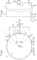
- FIG. 1 differs slightly from the shape of a circle 2 shown in dashed lines and can also be approximately regarded as elliptical.
- the greatest deviation of the contour of the tube 1 from that of the circle 2 is about 7% in the example shown.
- the major axis would be approximately 7% larger than the minor axis.
- a device is provided which has a cutting tool 3, here a milling tool, which is attached to a frame 4 which is radially adjustable relative to the tube 1.
- a relative rotary movement about the longitudinal central axis 5 of the tube 1 can be carried out between the tube 1 and the frame 4.
- the tool 3 can be supported on the tube via two in the direction of the rotary movement at the same angle of rotation distance ⁇ from 30 ° to 60 °, preferably 45 °, in front of and behind the tool 3 on the frame 4, the support rollers 6 being fixed in position on the tube, the axes of rotation of the support rollers being parallel to the longitudinal central axis 5 of the tube 1 lie.
- the frame 4 is in the radial direction towards the tube 1 under a resilient preload, which is brought about by a fluid cylinder 7, a hydraulic or pneumatic cylinder, the piston rod 8 of which is connected to the frame 4, the frame 4 being displaceable in the direction of the double arrow 9 is until the support rollers 6 rest on the circumference of the tube 1 and continue to remain in contact with the tube 1 in the course of processing the tube 1.
- the tube 1 is rotatably supported about its longitudinal central axis 5, bearing against bearing rollers 10.
- the bearing rollers 10 are arranged symmetrically on both sides of a vertical axial plane of the tube 1, wherein a plurality of bearing rollers 10 are each rotatably mounted on a shaft 11.
- One shaft 11 can be driven by a motor 12 so that the tube 1 can be rotated by the motor 12 about its longitudinal central axis 5 relative to the stationary frame 4.
- the tool 3 is mounted on the frame 4 radially to the tube 1 (in a manner not shown) and can be locked in the set position in order to adjust it to the desired diameter of the circle 2.
- the support rollers 6 are on one side of the cutting path of the tool 3 with the pipe 1 for contact bringable so that the driven by a frame-fixed motor 13 tool 3 in the round machining of the bottom of a groove for receiving a sealing ring 14 shown in FIG. 3 in the spigot end of a sleeve pipe 1 groove 15 can continue to be supported on the pipe circumference via the support rollers 6.
- the support rollers 6 it would also be possible to design the support rollers 6 so wide that they are supported on both sides of the groove 15 on the circumference of the tip end. If necessary, the support rollers 6 and the tool 3 could lie in the same radial plane of the tube 1.
- FIG. 3 further shows, the tip end of the tube 1, after the groove base of the groove 15 has been machined, is inserted together with the sealing ring 14 into the socket end of a tube 1 'to be connected in order to connect the two tubes 1 and 1' tightly .
- the frame 4 is shown rotated relative to the tube 1 in the circumferential direction thereof in the position shown in dashed lines in FIG. 1, although in the exemplary embodiment shown the tube is rotated about its longitudinal central axis 5 by the motor 12 relative to the round machining device .
- the machining point between pipe 1 and tool 3 is practically on circle 2 even after a relative rotation of pipe 1 and round machining device, in practice with a nominal diameter of pipe 1 of 600 mm with a initially maximum deviation of 1% from the nominal diameter after round machining resulted in a maximum deviation of only about 1.5 mm. Even with a nominal diameter of 1400 mm and an initial roundness error of 1%, the maximum diameter deviation after machining was also only about 1.5 mm, and therefore less in percentage terms.
- Modifications to the described embodiment may consist in that instead of the bearing rollers 10 arranged on one of the shafts 11, one of the support rollers 6 is driven by a motor in order to rotate the tube 1 during the round machining relative to the round machining device.
- the frame 4 can be moved horizontally on the guide rails (not shown) and at the same time on the vertical guide rails (not shown) together with the cylinder 7, so that the direction of displacement of the tool 3 on the frame aligns itself with the longitudinal central axis 5, it is also possible to arrange the frame 4 above the tube 1 so that the tool 3 is displaceable relative to the frame 4 in a vertical axial plane of the tube 1. In this case, the frame 4 only needs to be adjustable vertically, regardless of the size of the nominal diameter of the tube.
Landscapes
- Engineering & Computer Science (AREA)
- Mechanical Engineering (AREA)
- Mining & Mineral Resources (AREA)
- Automation & Control Theory (AREA)
- Milling Processes (AREA)
- Turning (AREA)
- Drilling And Boring (AREA)
Abstract
Description
- Die Erfindung bezieht sich auf eine Vorrichtung zur Rundbearbeitung eines Rohres, insbesondere Beton- oder Stahlbetonrohres, dessen Querschnitt etwa oval ist und geringfügig von der Kreisform abweicht, mittels eines spanabnehmenden Werkzeugs, insbesondere eines Fräswerkzeugs, das an einem radial relativ zum Rohr verstellbaren Gestell angebracht ist, wobei zwischen Rohr und Gestell eine relative Drehbewegung um die Längsmittelachse des Rohres ausführbar ist.
- Zur Abwasserableitung verwendete Muffenrohre aus Beton oder Stahlbeton werden beim Trennen der Formhälften bei der Herstellung häufig unrund, da das Entformen im noch nicht ausgehärteten Zustand der Rohre erfolgt und die Formhälften zunächst am Rohr haften, so daß sie das Rohr beim Trennen radial etwas auseinanderziehen. Der Rohrquerschnitt erhält dabei eine ovale, angenähert elliptische Form, bei der die große Ellipsenachse allerdings nur geringfügig, bis zu etwa 6 oder 7 % von der kleinen Ellipsenachse abweicht. Diese Unrundheit erschwert die Herstellung einer dichten Verbindung zwischen zwei derartigen Rohren, bei der das Spitzende des einen Rohres in die Muffe des anderen Rohres eingeführt und der Spalt zwischen Muffe und Spitzende durch einen elastomeren Dichtring abgedichtet wird. Dieser Dichtring muß zum Ausgleich der vornehmlich auf seiten des Spitzendes auftretenden Unrundheit überdimensioniert sein und erschwert dadurch das Zusammenstecken der Rohre, nachdem der Dichtring auf dem Spitzende angeordnet worden ist. Darüber hinaus führt die örtlich aufgrund der Überdimensionierung zu starke Verpressung des Dichtrings im Laufe der Zeit zu einer bleibenden Verformung des Dichtringmaterials, so daß der Dichtring thermisch bedingte Durchmesseränderungen der Rohre nicht mehr ausgleichen kann und die Verbindung undicht wird.
- Es ist daher eine Vorrichtung der eingangs erwähnten Art entwickelt worden, um die Unrundheit am Spitzende der Rohre zu beseitigen.
- Bei einer bekannten, im Handel erhältlichen Vorrichtung dieser Art wird das Fräswerkzeug auf einer Kreisbahn geführt, deren Durchmesser dem gewünschten Durchmesser des Rohres am Ort des Dichtrings entspricht. Zuvor wird das Rohr im Mittelpunkt der Kreisbahn zentriert. Zu diesem Zweck sind am Maschinengestell vier in Winkelabständen von 90° radial zum Mittelpunkt der Kreisbahn gerichtete Hydraulikzylinder befestigt, die außen über Rollen gegen das Rohr drücken. Nach der Zentrierung wird das Rohr axial auf vier Rollen geschoben, die einen Umkreis mit einem dem Innendurchmesser des Rohres entsprechenden Durchmesser tangieren und an der Stirnseite einer konzentrisch zum Mittelpunkt der Kreisbahn des Fräswerkzeugs starr gelagerten Tragscheibe um Achsen drehbar gelagert sind, die in einer Querebene des Rohres liegen. Danach werden die Hydraulikzylinder vom Umfang des Rohres abgestellt, und das rotierende Fräswerkzeug wird um das Rohr herumgeführt. Die beim Fräsen abgenommenen staubartigen Späne werden mit dem Kühlwasser des Fräswerkzeugs zu Schlamm vermischt, der bei dem Umlauf des Fräswerkzeugs verspritzt und zu einer erheblichen Verschmutzung der Vorrichtung selbst und ihrer Umgebung führt. Sodann ist diese Vorrichtung wegen der Vielzahl der Hydraulikzylinder aufwendig.
- Der Erfindung liegt die Aufgabe zugrunde, eine einfachere Vorrichtung der eingangs genannten Art anzugeben.
- Erfindungsgemäß ist diese Aufgabe dadurch gelöst, daß das Werkzeug über zwei in Richtung der Drehbewegung im gleichen Drehwinkelabstand von 30° bis 60° vor und hinter dem Werkzeug am Gestell ortsfest gelagerte Stützrollen, deren Drehachsen parallel zur Längsmittelachse des Rohres liegen, am Rohr abstützbar ist.
- Bei dieser Lösung kommt man mit lediglich einer Stellvorrichtung für die radiale Verstellung des Gestells aus. Obwohl sich das Werkzeug nur über zwei Stützrollen am Rohr abstützt, wird das Rohr dennoch überraschenderweise auf einer nahezu fehlerfreien Kreisbahn bearbeitet.
- Besonders gering sind die Abweichungen von der Kreisbahn, wenn der genannte Drehwinkelabstand etwa 45° beträgt.
- Sodann ist es günstig, wenn die Stützrollen wenigstens auf der einen Seite der Schneidbahn des Werkzeugs mit dem Rohr zur Anlage bringbar sind. Auf diese Weise ist es möglich, zur Aufnahme des Dichtrings, insbesondere eines Rundschnurrings (O-Rings), auch eine Nut mit einem praktisch kreisförmigen Innendurchmesser in der Außenseite des Rohres einzuarbeiten oder den Nutengrund einer zuvor bei der Herstellung des Rohres geformten Nut kreisförmig zu bearbeiten, ohne daß sich die Stützrollen am Nutengrund abstützen.
- Sodann kann dafür gesorgt sein, daß das Rohr um seine Längsmittelachse, an Lagerrollen anliegend, drehbar gelagert und durch einen Motor um seine Längsmittelachse in Drehung versetzbar ist. Bei dieser Ausbildung kann das Werkzeug ortsfest bleiben, so daß eine einfache Abführung von Frässchlamm ohne allseitige Verschmutzung der Vorrichtung und ihrer Umgebung möglich ist.
- Das Gestell sollte in Radialrichtung zum Rohr hin unter einer nachgiebigen Vorbelastung stehen. Diese Vorbelastung stellt sicher, daß die Stützrollen trotz der Unrundheit des Rohres während der relativen Drehung von Rohr und Gestell ständig am Rohr anliegen.
- Ferner sollte das Werkzeug am Gestell radial zum Rohr verstellbar gelagert und in der eingestellten Lage feststellbar sein. Auf diese Weise ist das Werkzeug in einfacher Weise auf den gewünschten Rohrdurchmesser einstellbar.
- Die Erfindung und ihre Weiterbildung werden nachstehend anhand der Zeichnung eines bevorzugten Ausführungsbeispiels näher beschrieben. Es zeigen:
- Fig. 1 eine schematische Darstellung eines rund zu bearbeitenden Rohres und einer erfindungsgemäßen Rundbearbeitungsvorrichtung vom einen Ende des Rohres her gesehen,
- Fig. 2 eine schemtische Seitenansicht des Rohres nach Fig. 1 und der Rundbearbeitungsvorrichtung und
- Fig. 3 einen Ausschnitt der zu verbindenden Enden zweier Muffenrohre aus Beton oder Stahlbeton im Axialschnitt.
- In Fig. 1 ist zur Vereinfachung der Darstellung lediglich die Außenkontur des Querschnitts eines etwa ovalen Rohres 1 dargestellt, die geringfügig von der Form eines gestrichelt dargestellten Kreises 2 abweicht und angenähert auch als elliptisch angesehen werden kann. Die größte Abweichung der Kontur des Rohres 1 von der des Kreises 2 beträgt im dargestellten Beispiel etwa 7 %. Bei einer entsprechenden Ellipse wäre mithin die große Achse etwa um 7 % größer als die kleine Achse. Zur Rundbearbeitung des Rohres 1, so daß seine Kontur zumindest angenähert der des Kreises 2 entspricht, ist eine Vorrichtung vorgesehen, die ein spanabnehmendes Werkzeug 3, hier ein Fräswerkzeug, aufweist, das an einem radial relativ zum Rohr 1 verstellbaren Gestell 4 angebracht ist. Zwischen Rohr 1 und Gestell 4 ist eine relative Drehbewegung um die Längsmittelachse 5 des Rohres 1 ausführbar. Das Werkzeug 3 ist über zwei in Richtung der Drehbewegung im gleichen Drehwinkelabstand β von 30° bis 60°, vorzugsweise 45°, vor und hinter dem Werkzeug 3 am Gestell 4 ortsfest gelagerte Stützrollen 6 am Rohr abstützbar, wobei die Drehachsen der Stützrollen parallel zur Längsmittelachse 5 des Rohres 1 liegen.
- Das Gestell 4 steht in Radialrichtung zum Rohr 1 hin unter einer nachgiebigen Vorbelastung, die durch einen Fluidzylinder 7, einen Hydraulik- oder Pneumatikzylinder, dessen Kolbenstange 8 mit dem Gestell 4 verbunden ist, bewirkt wird, wobei das Gestell 4 in Richtung des Doppelpfeils 9 verschiebbar ist, bis die Stützrollen 6 am Umfang des Rohres 1 anliegen und im Verlaufe der Bearbeitung des Rohres 1 weiterhin mit dem Rohr 1 in Berührung bleiben.
- Das Rohr 1 ist um seine Längsmittelachse 5, an Lagerrollen 10 anliegend, drehbar gelagert. Die Lagerrollen 10 sind symmetrisch zu beiden Seiten einer vertikalen Axialebene des Rohres 1 angeordnet, wobei mehrere Lagerrollen 10 jeweils auf einer Welle 11 drehfest gelagert sind. Die eine Welle 11 ist durch einen Motor 12 antreibbar, so daß das Rohr 1 durch den Motor 12 um seine Längsmittelachse 5 relativ zu dem ortsfesten Gestell 4 in Drehung versetzbar ist.
- Das Werkzeug 3 ist am Gestell 4 radial zum Rohr 1 (in nicht dargestellter Weise) verstellbar gelagert und in der eingestellten Lage feststellbar, um es auf den gewünschten Durchmesser des Kreises 2 einzustellen.
- Wie Fig. 2 zeigt, sind die Stützrollen 6 auf der einen Seite der Schneidbahn des Werkzeugs 3 mit dem Rohr 1 zur Anlage bringbar, so daß das von einem gestellfesten Motor 13 angetriebene Werkzeug 3 bei der Rundbearbeitung des Nutengrundes einer zur Aufnahme eines Dichtrings 14 gemäß Fig. 3 im Spitzende eines Muffenrohres 1 ausgebildeten Nut 15 sich weiterhin über die Stützrollen 6 am Rohrumfang abstützen kann. Allerdings wäre es auch möglich, die Stützrollen 6 so breit auszubilden, daß sie sich beiderseits der Nut 15 am Umfang des Spitzendes abstützen. Gegebenenfalls könnten die Stützrollen 6 und das Werkzeug 3 in der gleichen Radialebene des Rohres 1 liegen.
- Wie Fig. 3 weiter zeigt, wird das Spitzende des Rohres 1, nachdem der Nutengrund der Nut 15 bearbeitet worden ist, zusammen mit dem Dichtring 14 in das Muffenende eines anzuschließenden Rohres 1' eingeführt, um die beiden Rohre 1 und 1' dicht zu verbinden.
- Zur Vereinfachung der Darstellung der Wirkungsweise der Rundbearbeitungsvorrichtung ist in Fig. 1 das Gestell 4 relativ zum Rohr 1 in dessen Umfangsrichtung in die gestrichelt dargestellte Lage verdreht eingezeichnet, obwohl im dargestellten Ausführungsbeispiel das Rohr durch den Motor 12 relativ zur Rundbearbeitungsvorrichtung um seine Längsmittelachse 5 gedreht wird. Wie die gestrichelt dargestellte Lage der Rundbearbeitungsvorrichtung zeigt, liegt der Bearbeitungspunkt zwischen Rohr 1 und Werkzeug 3 auch nach einer relativen Verdrehung von Rohr 1 und Rundbearbeitungsvorrichtung praktisch auf dem Kreis 2, wobei sich in der Praxis bei einem Nenndurchmesser des Rohres 1 von 600 mm mit einer anfänglich maximalen Abweichung von 1 % vom Nenndurchmesser nach der Rundbearbeitung eine maximale Abweichung von nur etwa 1,5 mm ergab. Auch bei einem Nenndurchmesser von 1400 mm und einem anfänglichen Rundheits-Fehler von 1 % betrug die maximale Durchmesserabweichung nach der Bearbeitung ebenfalls nur etwa 1,5 mm, prozentual mithin weniger.
- Die Tatsache, daß der Bearbeitungspunkt des Werkzeugs 3 im Verlaufe der Bearbeitung praktisch auf einer Kreisbahn um die Längsmittelachse 5 bleibt, läßt sich anschaulich dadurch erklären, daß sich die eine Stützrolle 6 im Verlaufe der Bearbeitung etwa um den gleichen Betrag von der Längsmittelachse entfernt, wie sich die andere Stützrolle 6 der Längsmittelachse 5 nähert, so daß das in der Mitte zwischen beiden Stützrollen 6 liegende Werkzeug 3 praktisch den gleichen Abstand von der Längsmittelachse 5 beibehält. Dies setzt lediglich voraus, daß die sogenannte "numerische Exzentrizität" der angenähert durch das Rohr 1 dargestellten Ellipse verhältnismäßig klein ist, wie es in der Praxis bei derartigen Rohren der Fall ist.
- Abwandlungen von dem beschriebenen Ausführungsbeispiel können darin bestehen, daß anstelle der auf einer der Wellen 11 angeordneten Lagerrollen 10 eine der Stützrollen 6 durch einen Motor angetrieben wird, um das Rohr 1 während der Rundbearbeitung relativ zur Rundbearbeitungsvorrichtung zu drehen.
- Während das Gestell 4 horizontal auf (nicht dargestellten) Führungsschienen und zugleich auf (nicht dargestellten) vertikalen Führungsschienen zusammen mit dem Zylinder 7 verschiebbar ist, so daß die Verschiebungsrichtung des Werkzeugs 3 am Gestell sich selbsttätig auf die Längsmittelachse 5 ausrichtet, ist es auch möglich, das Gestell 4 oberhalb des Rohres 1 so anzuordnen, daß das Werkzeug 3 in einer vertikalen Axialebene des Rohres 1 relativ zum Gestell 4 verschiebbar ist. In diesem Falle braucht das Gestell 4 lediglich vertikal, unabhängig von der Größe des Nenndurchmesser des Rohres, verstellbar zu sein.
- Statt die Stützrollen 6 mit der Außenseite des Rohres 1 zur Anlage zu bringen, können sie auch mit der Innenseite des Rohres 1 zur Anlage gebracht werden, um das Werkzeug 3 am Rohr 1 abzustützen.
- Sodann kann anstelle der Ausbildung einer Nut im Spitzende des Rohres 1 auch nur das Spitzende rund bearbeitet werden.
Claims (6)
- Vorrichtung zur Rundbearbeitung eines Rohres, insbesondere Beton- oder Stahlbetonrohres, dessen Querschnitt etwa oval ist und geringfügig von der Kreisform abweicht, mittels eines spanabnehmenden Werkzeugs (3), insbesondere eines Fräswerkzeugs, das an einem radial relativ zum Rohr (1) verstellbaren Gestell (4) angebracht ist, wobei zwischen Rohr (1) und Gestell (4) eine relative Drehbewegung um die Längsmittelachse (5) des Rohres (1) ausführbar ist, dadurch gekennzeichnet, daß das Werkzeug (3) über zwei in Richtung der Drehbewegung im gleichen Drehwinkelabstand (β) von 30° bis 60° vor und hinter dem Werkzeug (3) am Gestell (4) ortsfest gelagerte Stützrollen (6), deren Drehachsen parallel zur Längsmittelachse (5) des Rohres (1) liegen, am Rohr (1) abstützbar ist.
- Vorrichtung nach Anspruch 1,
dadurch gekennzeichnet,
daß der Drehwinkelabstand (β) etwa 45° beträgt. - Vorrichtung nach Anspruch 1 oder 2,
dadurch gekennzeichnet,
daß die Stützrollen (6) wenigstens auf der einen Seite der Schneidbahn des Werkzeugs (3) mit dem Rohr (1) zur Anlage bringbar sind. - Vorrichtung nach einem der Ansprüche 1 bis 3,
dadurch gekennzeichnet,
daß das Rohr (1) um seine Längsmittelachse (5), an Lagerrollen (10) anliegend, drehbar gelagert und durch einen Motor (12) um seine Längsmittelachse (5) in Drehung versetzbar ist. - Vorrichtung nach einem der Ansprüche 1 bis 4,
dadurch gekennzeichnet,
daß das Gestell (4) in Radialrichtung zum Rohr (1) hin unter einer nachgiebigen Vorbelastung steht. - Vorrichtung nach einem der Ansprüche 1 bis 5,
dadurch gekennzeichnet,
daß das Werkzeug (3) am Gestell (4) radial zum Rohr (1) verstellbar gelagert und in der eingestellten Lage feststellbar ist.
Applications Claiming Priority (2)
| Application Number | Priority Date | Filing Date | Title |
|---|---|---|---|
| DE9205382U DE9205382U1 (de) | 1992-04-18 | 1992-04-18 | Vorrichtung zum Bearbeiten von kreisrunden Rohren aus Beton und Stahlbeton |
| DE9205382U | 1992-04-18 |
Publications (2)
| Publication Number | Publication Date |
|---|---|
| EP0566879A1 true EP0566879A1 (de) | 1993-10-27 |
| EP0566879B1 EP0566879B1 (de) | 1997-03-05 |
Family
ID=6878671
Family Applications (1)
| Application Number | Title | Priority Date | Filing Date |
|---|---|---|---|
| EP93104716A Expired - Lifetime EP0566879B1 (de) | 1992-04-18 | 1993-03-23 | Vorrichtung zur Rundbearbeitung eines Rohres |
Country Status (3)
| Country | Link |
|---|---|
| EP (1) | EP0566879B1 (de) |
| AT (1) | ATE149410T1 (de) |
| DE (2) | DE9205382U1 (de) |
Cited By (3)
| Publication number | Priority date | Publication date | Assignee | Title |
|---|---|---|---|---|
| US5595524A (en) * | 1995-02-17 | 1997-01-21 | Npc, Inc. | Grinding apparatus and method which supports a workpiece on the surface being ground |
| DE4403342C3 (de) * | 1993-02-05 | 2002-08-29 | Schindler Steinbearbeitungsmas | Vorrichtung zum Bearbeiten des Endes eines Beton- oder Stahlbetonrohres |
| WO2005032784A1 (en) * | 2003-10-08 | 2005-04-14 | James Hardie International Finance B.V. | A fibre reinforced cement column and method of forming the same |
Families Citing this family (1)
| Publication number | Priority date | Publication date | Assignee | Title |
|---|---|---|---|---|
| DE4328594C1 (de) * | 1993-08-25 | 1995-01-26 | Pfeiffer Maschf Ettlingen | Vorrichtung und Verfahren zum Nacharbeiten eines Werkstücks |
Citations (5)
| Publication number | Priority date | Publication date | Assignee | Title |
|---|---|---|---|---|
| US3699828A (en) * | 1970-12-02 | 1972-10-24 | Victaulic Co Of America | Pipe groover |
| US3820424A (en) * | 1972-10-17 | 1974-06-28 | J George | Pipe cutter |
| DE2605196A1 (de) * | 1976-02-10 | 1977-08-11 | Cremer & Breuer Keramische | Verfahren zum profilieren der wandung eines aus noch verformbarem, insbesondere keramischem material bestehenden rohres, sowie vorrichtung zur durchfuehrung des verfahrens |
| DE2949921A1 (de) * | 1979-12-12 | 1981-06-19 | Goetze Ag, 5093 Burscheid | Vorrichtung zum mechanischen umfangsbearbeiten von ring- oder buechsenfoermigen werkstuecken |
| US4612730A (en) * | 1985-08-29 | 1986-09-23 | Npc Systems, Inc. | Mechanical centering apparatus and method |
-
1992
- 1992-04-18 DE DE9205382U patent/DE9205382U1/de not_active Expired - Lifetime
-
1993
- 1993-03-23 EP EP93104716A patent/EP0566879B1/de not_active Expired - Lifetime
- 1993-03-23 DE DE59305558T patent/DE59305558D1/de not_active Expired - Fee Related
- 1993-03-23 AT AT93104716T patent/ATE149410T1/de not_active IP Right Cessation
Patent Citations (5)
| Publication number | Priority date | Publication date | Assignee | Title |
|---|---|---|---|---|
| US3699828A (en) * | 1970-12-02 | 1972-10-24 | Victaulic Co Of America | Pipe groover |
| US3820424A (en) * | 1972-10-17 | 1974-06-28 | J George | Pipe cutter |
| DE2605196A1 (de) * | 1976-02-10 | 1977-08-11 | Cremer & Breuer Keramische | Verfahren zum profilieren der wandung eines aus noch verformbarem, insbesondere keramischem material bestehenden rohres, sowie vorrichtung zur durchfuehrung des verfahrens |
| DE2949921A1 (de) * | 1979-12-12 | 1981-06-19 | Goetze Ag, 5093 Burscheid | Vorrichtung zum mechanischen umfangsbearbeiten von ring- oder buechsenfoermigen werkstuecken |
| US4612730A (en) * | 1985-08-29 | 1986-09-23 | Npc Systems, Inc. | Mechanical centering apparatus and method |
Cited By (3)
| Publication number | Priority date | Publication date | Assignee | Title |
|---|---|---|---|---|
| DE4403342C3 (de) * | 1993-02-05 | 2002-08-29 | Schindler Steinbearbeitungsmas | Vorrichtung zum Bearbeiten des Endes eines Beton- oder Stahlbetonrohres |
| US5595524A (en) * | 1995-02-17 | 1997-01-21 | Npc, Inc. | Grinding apparatus and method which supports a workpiece on the surface being ground |
| WO2005032784A1 (en) * | 2003-10-08 | 2005-04-14 | James Hardie International Finance B.V. | A fibre reinforced cement column and method of forming the same |
Also Published As
| Publication number | Publication date |
|---|---|
| EP0566879B1 (de) | 1997-03-05 |
| DE59305558D1 (de) | 1997-04-10 |
| ATE149410T1 (de) | 1997-03-15 |
| DE9205382U1 (de) | 1992-10-22 |
Similar Documents
| Publication | Publication Date | Title |
|---|---|---|
| DE2234082C2 (de) | Rohrabschneider | |
| EP0644008A1 (de) | Vorrichtung zum Sägen von Schlitzen in Well- und Verbundrohre | |
| EP0513524A2 (de) | Rohrtrennvorrichtung | |
| DE19511310C1 (de) | Rohrinnenmanipulator | |
| EP0566879B1 (de) | Vorrichtung zur Rundbearbeitung eines Rohres | |
| EP0772501B1 (de) | Verfahren zur bildung eines geneckten und gebördelten abschnitts an einem zylindrischen hohlkörper und vorrichtung zum durchführen des verfahrens | |
| DE2921977A1 (de) | Wellenantriebselement | |
| DE2511942C2 (de) | Vorrichtung zur klemmenden befestigung einer huelse, z.b. metallhuelse, an dem ende eines schlauches, kabels o.dgl. | |
| DE3717423C2 (de) | ||
| EP0127053A2 (de) | Arbeitsgerät zum Bearbeiten der Schnittstelle eines Rohres | |
| EP0154030B1 (de) | Aufweitvorrichtung für Rohrenden | |
| DE2646490C3 (de) | Einrichtung zum Bearbeiten des Außenumfangs eines dünnwandigen Rohrs | |
| DE4403342C2 (de) | Vorrichtung zum Bearbeiten des Endes eines Beton- oder Stahlbetonrohres | |
| EP3161197B1 (de) | Anpresseinrichtung zum anpressen eines geflechtschlauches an einen bauteilkern und flechtmaschine | |
| DE2549671A1 (de) | Maschine zum bearbeiten von rohrboegen | |
| DE19519953A1 (de) | Sägemaschine zum genauen Abstechen von ringförmigen Rohrabschnitten von Rohren | |
| DE972575C (de) | Vorrichtung zum Kaltbiegen duennwandiger Metallrohre | |
| EP1004392A2 (de) | Schwenktisch einer Werkzeugmaschine | |
| DE414790C (de) | Herstellung nahtloser Rohre | |
| DE650471C (de) | Vorrichtung zum Auswalzen | |
| DE3116389C2 (de) | Mit Eigenantrieb versehene Brennschneidmaschine für Schrägschnitt | |
| EP0610690B1 (de) | Verfahren und Vorrichtung zur Herstellung eines Spitzendes an einem Beton- oder Stahlbetonrohr | |
| DE29709802U1 (de) | Vorrichtung zur Aufnahme und Halterung einer hohlzylindrischen Druckhülse | |
| DE19634307C2 (de) | Hydraulische Anlage zur Bildung einer Rohrziehangel | |
| AT344471B (de) | Vorrichtung zum entfernen des aeusseren ringwulstes von im elektrischen widerstands-stumpfschweissverfahren hergestellten rohrstoessen |
Legal Events
| Date | Code | Title | Description |
|---|---|---|---|
| PUAI | Public reference made under article 153(3) epc to a published international application that has entered the european phase |
Free format text: ORIGINAL CODE: 0009012 |
|
| 17P | Request for examination filed |
Effective date: 19930806 |
|
| AK | Designated contracting states |
Kind code of ref document: A1 Designated state(s): AT DE ES FR IT |
|
| 17Q | First examination report despatched |
Effective date: 19950505 |
|
| GRAG | Despatch of communication of intention to grant |
Free format text: ORIGINAL CODE: EPIDOS AGRA |
|
| GRAH | Despatch of communication of intention to grant a patent |
Free format text: ORIGINAL CODE: EPIDOS IGRA |
|
| GRAH | Despatch of communication of intention to grant a patent |
Free format text: ORIGINAL CODE: EPIDOS IGRA |
|
| GRAA | (expected) grant |
Free format text: ORIGINAL CODE: 0009210 |
|
| AK | Designated contracting states |
Kind code of ref document: B1 Designated state(s): AT DE ES FR IT |
|
| PG25 | Lapsed in a contracting state [announced via postgrant information from national office to epo] |
Ref country code: IT Free format text: LAPSE BECAUSE OF FAILURE TO SUBMIT A TRANSLATION OF THE DESCRIPTION OR TO PAY THE FEE WITHIN THE PRE;WARNING: LAPSES OF ITALIAN PATENTS WITH EFFECTIVE DATE BEFORE 2007 MAY HAVE OCCURRED AT ANY TIME BEFORE 2007. THE CORRECT EFFECTIVE DATE MAY BE DIFFERENT FROM THE ONE RECORDED.SCRIBED TIME-LIMIT Effective date: 19970305 Ref country code: ES Free format text: THE PATENT HAS BEEN ANNULLED BY A DECISION OF A NATIONAL AUTHORITY Effective date: 19970305 |
|
| REF | Corresponds to: |
Ref document number: 149410 Country of ref document: AT Date of ref document: 19970315 Kind code of ref document: T |
|
| PG25 | Lapsed in a contracting state [announced via postgrant information from national office to epo] |
Ref country code: AT Free format text: LAPSE BECAUSE OF NON-PAYMENT OF DUE FEES Effective date: 19970323 |
|
| REF | Corresponds to: |
Ref document number: 59305558 Country of ref document: DE Date of ref document: 19970410 |
|
| ET | Fr: translation filed | ||
| PLBE | No opposition filed within time limit |
Free format text: ORIGINAL CODE: 0009261 |
|
| 26N | No opposition filed | ||
| PGFP | Annual fee paid to national office [announced via postgrant information from national office to epo] |
Ref country code: FR Payment date: 19990329 Year of fee payment: 7 |
|
| PGFP | Annual fee paid to national office [announced via postgrant information from national office to epo] |
Ref country code: DE Payment date: 19990428 Year of fee payment: 7 |
|
| PG25 | Lapsed in a contracting state [announced via postgrant information from national office to epo] |
Ref country code: FR Free format text: LAPSE BECAUSE OF NON-PAYMENT OF DUE FEES Effective date: 20001130 |
|
| REG | Reference to a national code |
Ref country code: FR Ref legal event code: ST |
|
| PG25 | Lapsed in a contracting state [announced via postgrant information from national office to epo] |
Ref country code: DE Free format text: LAPSE BECAUSE OF NON-PAYMENT OF DUE FEES Effective date: 20010103 |