EP0567005A2 - Retarding device for a web-roll - Google Patents
Retarding device for a web-roll Download PDFInfo
- Publication number
- EP0567005A2 EP0567005A2 EP93106200A EP93106200A EP0567005A2 EP 0567005 A2 EP0567005 A2 EP 0567005A2 EP 93106200 A EP93106200 A EP 93106200A EP 93106200 A EP93106200 A EP 93106200A EP 0567005 A2 EP0567005 A2 EP 0567005A2
- Authority
- EP
- European Patent Office
- Prior art keywords
- brake
- pressure chamber
- plunger
- winding roll
- web
- Prior art date
- Legal status (The legal status is an assumption and is not a legal conclusion. Google has not performed a legal analysis and makes no representation as to the accuracy of the status listed.)
- Granted
Links
Images

Classifications
-
- B—PERFORMING OPERATIONS; TRANSPORTING
- B65—CONVEYING; PACKING; STORING; HANDLING THIN OR FILAMENTARY MATERIAL
- B65H—HANDLING THIN OR FILAMENTARY MATERIAL, e.g. SHEETS, WEBS, CABLES
- B65H23/00—Registering, tensioning, smoothing or guiding webs
- B65H23/04—Registering, tensioning, smoothing or guiding webs longitudinally
- B65H23/06—Registering, tensioning, smoothing or guiding webs longitudinally by retarding devices, e.g. acting on web-roll spindle
- B65H23/063—Registering, tensioning, smoothing or guiding webs longitudinally by retarding devices, e.g. acting on web-roll spindle and controlling web tension
-
- B—PERFORMING OPERATIONS; TRANSPORTING
- B65—CONVEYING; PACKING; STORING; HANDLING THIN OR FILAMENTARY MATERIAL
- B65H—HANDLING THIN OR FILAMENTARY MATERIAL, e.g. SHEETS, WEBS, CABLES
- B65H2403/00—Power transmission; Driving means
- B65H2403/70—Clutches; Couplings
- B65H2403/72—Clutches, brakes, e.g. one-way clutch +F204
- B65H2403/725—Brakes
- B65H2403/7255—Disc brakes
Definitions
- the invention relates to a deceleration device for a winding roll according to the preamble of claim 1.
- a deceleration device for a winding roll for regulating the web tension is known (DE-OS 23 44 591), which has a pendulum roller which senses the web tension and a control device for the braking force of a disc brake acting in the center of the winding roll which is influenced by its movement as a result of the change in the web tension. whose brake pads are actuated by a plunger of a working cylinder which rests on the end face of a membrane dividing a pressure chamber.
- the disadvantage of this device is that the braking force can only be increased in stages.
- the braking force required to maintain the web tension is reduced.
- the result of this is that, in particular with simple control devices with a pendulum roller which is wound as a function of the position of the web running off the winding roller, brakes which are largely proportionally controlled leave the pendulum roller with its winding roller diameter decreasing its favorable working range. This means that during the automatic gluing process of the web running from the unwound small roll to the new winding roll, with the requirement of a suddenly increasing braking force, it takes an unfavorable position, so that the web can tear due to large web tension fluctuations.
- Another disadvantage of the known device is that the friction losses for guiding the tappet with the decrease in diameter of the running winding reel and thus inevitably reducing braking force have an increasingly disruptive effect on sensitive control of the web tension.
- the invention has for its object to design a delay device for a winding reel according to the preamble of claim 1 such that with simple technical means a favorable control behavior is ensured even with decreasing roll diameter and during the gluing process of the running web to the new winding reel.
- This solution has the advantage that due to the smooth transmission of the braking force by the plunger Falsification of the regulation is avoided and, on the other hand, the pendulum roller is located in a working area which is particularly favorable for the gluing process of the new winding roller, due to the temporary application of a counterpressure to the working cylinder even with a low braking force.
- an adjustable throttle valve is arranged in its pressure medium supply line, so that the differential force counteracting the end pressure chamber is delayed.
- the further subclaims reflect the advantageous refinements of the subject matter of the invention, the integration of the working cylinder in a brake caliper, in addition to the low technical outlay for the compact assembly, also offering particularly spatial advantages.
- a floating arrangement of the brake caliper in connection with the resilient suspension of a brake pad enables effective, uniformly uniform transmission of the braking force to the brake disc on both sides.
- The are each with a pressure medium connection 12; 13 provided pressure chambers 9; 10 once bounded by a membrane 15 clamped between a cover 14 of the housing 8 and on the other hand by a further membrane 16 fastened to the latter in the pressure chamber 10.
- both membranes 15; 16 is coaxially suspended from the housing 8 in a bore 17, a plunger 18 running smoothly, the diaphragm 15 clamped between the cover 14 of the housing 8 on the end of the plunger 18 and the second diaphragm 16 axially offset in the longitudinal direction in the longitudinal direction between a collar 19 and a detachable spacer 20 are clamped with the aid of a nut 21 which can be screwed onto a threaded attachment of the plunger 18.
- both sides of the brake disc 6 are each in the U-shaped, open towards the brake disc 6 recess 23 from a base 24; 25 and a bonded brake pad 26; 27 existing brake pad 28; 29 arranged. While the support 24 of the one brake pad 28, which is in direct contact with the tappet 18, is fastened movably in the direction of movement of the spring band steel 30 screwed to the housing 8 under its elastic deformation, the other brake pad 29 is firmly screwed to the housing 8, so that in conjunction with the floating arrangement of the entire brake caliper 7, the braking force exerted by the plunger 18 via both brake pads 28; 29 is transmitted to the brake disc 6 on both sides.
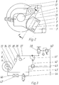
- Fig. 2 shows a schematic representation of the lateral arrangement of the two studs 2; 3 guided brake caliper 7 on the holding arm 1 for the winding roller, not shown.
- the latter is received by the spindle 4, which is mounted in a semicircular recess 31 of the holding arm 1 and secured by a pivoting lever 32 and can be removed from the holder together with the brake disc 6 attached to it with the brake caliper 7 remaining on the holding arm 1.
- Fig. 3 shows the control loop for regulating the web tension.
- the web 34 running from the winding roller 33 wraps around the between two pull rollers 35; 36 arranged, mounted in a pivotable double lever 37 pendulum roller 38, which is loaded by a working cylinder 39 acting on the other end of the double lever with the setpoint value for the web tension that can be set via an upstream pressure control valve 40.
- the changes in the web tension sensed by the pendulum roller 38 are transmitted via a control cam 41 attached to the double lever 37 thereof to the roller lever 42 of a pressure control valve 43 which is in connection with the pressure chamber 9 of the brake caliper 7 (FIG. 1) on the output side in the operating state.
- the pendulum roller 38 With a decreasing diameter of the running winding roll, the pendulum roller 38 leaves its favorable working range, which is necessary in particular for the gluing process of a new winding roll, due to the decreasing braking force transmitted by the plunger 18. This state is countered after reaching a predeterminable diameter of the winding roll with the running web 34 by switching on the annular pressure chamber 10, which generates a differential force counteracting the braking force, to the supply line 45 for the end-side pressure chamber 9 by means of a directional valve 44.
- a higher brake pressure to be newly adjusted via the pendulum roller is therefore required for the same braking force, as a result of which the pendulum roller 38 inevitably when the is switched off annular pressure chamber 10 connected, requiring a greater braking force sticking a new winding roller assumes a favorable working position for the control process.
Landscapes
- Controlling Rewinding, Feeding, Winding, Or Abnormalities Of Webs (AREA)
Abstract
Verzögerungsvorrichtung für eine Wickelrolle (33), insbesondere in Rotationsdruckmaschinen, mit einer die Bahn (34) abfühlenden Pendelwalze (38) und einer von deren Bewegung infolge Änderung der Bahnspannung beeinflußten Regeleinrichtung für die Bremskraft einer im Zentrum der Wickelrolle (33) angreifenden Scheibenbremse (6), deren Bremsklötze (28,29) von einem stirnseitig an einer eine Druckkammer (9,10) abteilenden Membran (15) anliegenden Stößel (18) eines Arbeitszylinders (11) betätigt werden. Um eine derartige Vorrichtung so zu gestalten, daß mit einfachen technischen Mitteln ein günstiges Regelverhalten auch bei kleiner werdendem Rollendurchmesser und während des Anklebevorganges der ablaufenden Bahn (34) an die neue Wickelrolle (33) gewährleistet wird, ist der Stößel (18) an dieser Membran (15) sowie zu dieser längs des Stößels (18) versetzt mindestens an einer weiteren Membran (16), die eine eine entgegengerichtete Differenzkraft zur stirnseitigen Druckkammer (9) erzeugende, zu deren Druckmittelzuleitung (45) zuschaltbare ringförmige Druckkammer (10) abteilt, reibungslos axial beweglich aufgehängt.
Description
Die Erfindung betrifft eine Verzögerungsvorrichtung für eine Wickelrolle nach dem Oberbegriff des Anspruches 1.The invention relates to a deceleration device for a winding roll according to the preamble of
Es ist eine Verzögerungsvorrichtung für eine Wickelrolle zur Regelung der Bahnspannung bekannt (DE-OS 23 44 591), die mit einer die Bahnspannung abfühlenden Pendelwalze und einer von deren Bewegung infolge Änderung der Bahnspannung beeinflußten Regeleinrichtung für die Bremskraft einer im Zentrum der Wickelrolle angreifenden Scheibenbremse, deren Bremsklötze von einem stirnseitig an einer eine Druckkammer abteilenden Membran anliegenden Stößel eines Arbeitszylinders betätigt werden, ausgestattet ist.A deceleration device for a winding roll for regulating the web tension is known (
Der Nachteil dieser Vorrichtung ist, daß die Bremskraft lediglich in Stufen erhöht werden kann. Hingegen verringert sich mit kleiner werdendem Durchmesser der Wickelrolle beim Abwickelvorgang die zur Aufrechterhaltung der Bahnspannung erforderliche Bremskraft. Die Folge davon ist, daß insbesondere bei einfachen Regelvorrichtungen mit in Abhängigkeit zur Stellung der von der Wickelrolle ablaufenden Bahn umschlungenen Pendelwalze weitestgehend proportional geregelten Bremsen die Pendelwalze mit kleiner werdenden Wickelrollendurchmesser ihren günstigen Arbeitsbereich verläßt. Damit nimmt sie beim automatischen Anklebevorgang der von der abgewickelten kleinen Rolle ablaufenden Bahn an die neue Wickelrolle mit dem Erfordernis einer plötzlich ansteigenden Bremskraft eine ungünstige Lage ein, so daß die Bahn auf Grund zu großer Bahnspannungsschwankungen reißen kann.The disadvantage of this device is that the braking force can only be increased in stages. On the other hand, as the diameter of the winding roll becomes smaller during the unwinding process, the braking force required to maintain the web tension is reduced. The result of this is that, in particular with simple control devices with a pendulum roller which is wound as a function of the position of the web running off the winding roller, brakes which are largely proportionally controlled leave the pendulum roller with its winding roller diameter decreasing its favorable working range. This means that during the automatic gluing process of the web running from the unwound small roll to the new winding roll, with the requirement of a suddenly increasing braking force, it takes an unfavorable position, so that the web can tear due to large web tension fluctuations.
Ein weiterer Nachteil der bekannten Vorrichtung ist, daß sich die Reibungsverluste für die Führung des Stößels mit der Durchmesserabnahme der ablaufenden Wickelrolle und damit sich zwangsläufig verringernder Bremskraft zunehmend störend auf eine feinfühlige Regelung der Bahnspannung auswirken.Another disadvantage of the known device is that the friction losses for guiding the tappet with the decrease in diameter of the running winding reel and thus inevitably reducing braking force have an increasingly disruptive effect on sensitive control of the web tension.
Der Erfindung liegt die Aufgabe zugrunde, eine Verzögerungsvorrichtung für eine Wickelrolle gemäß dem Oberbegriff von Anspruch 1 derart zu gestalten, daß mit einfachen technischen Mitteln ein günstiges Regelverhalten auch bei kleiner werdendem Rollendurchmesser und während des Anklebevorganges der ablaufenden Bahn an die neue Wickelrolle gewährleistet wird.The invention has for its object to design a delay device for a winding reel according to the preamble of
Die Aufgabe wird gemäß den Erfindungsmerkmalen des Anspruches 1 gelöst. Diese Lösung hat den Vorteil, daß durch reibungslose übertragung der Bremskraft durch den Stößel eine diesbezügliche Verfälschung der Regelung vermieden wird und zum anderen sich die Pendelwalze durch die zeitweise Aufschaltung eines Gegendruckes am Arbeitszylinder auch bei einer geringen Bremskraft in einem insbesondere für den Anklebevorgang der neuen Wickelrolle günstigen Arbeitsbereich befindet.The object is achieved according to the inventive features of
Für die Gestaltung der Regelcharakteristik der Vorrichtung während des Druckaufbaues in der ringförmigen Druckkammer nach deren Zuschaltung ist es vorteilhaft, wenn erfindungsgemäß in deren Druckmittelzuleitung ein einstellbares Drosselventil angeordnet ist, so daß die der stirnseitigen Druckkammer entgegenwirkende Differenzkraft verzögert wirksam wird.For the design of the control characteristic of the device during the pressure build-up in the annular pressure chamber after it has been switched on, it is advantageous if, according to the invention, an adjustable throttle valve is arranged in its pressure medium supply line, so that the differential force counteracting the end pressure chamber is delayed.
Die weiteren Unteransprüche geben die vorteilhaften Ausgestaltungen des Erfindungsgegenstandes wieder, wobei die Integration des Arbeitszylinders in einen Bremssattel neben dem geringen technischen Aufwand für die kompakte Baugruppe auch besonders räumliche Vorteile bietet. Eine schwimmende Anordnung des Bremssattels in Verbindung mit der federnden Aufhängung eines Bremsklotzes ermöglicht eine effektive, beiderseitig gleichmäßige übertragung der Bremskraft auf die Bremsscheibe.The further subclaims reflect the advantageous refinements of the subject matter of the invention, the integration of the working cylinder in a brake caliper, in addition to the low technical outlay for the compact assembly, also offering particularly spatial advantages. A floating arrangement of the brake caliper in connection with the resilient suspension of a brake pad enables effective, uniformly uniform transmission of the braking force to the brake disc on both sides.
Die Erfindung soll nachfolgend an einem Ausführungsbeispiel näher erläutert werden. In den zugehörigen Zeichnungen zeigen:
- Fig. 1:
- einen Querschnitt gemäß Schnitt A-A von Fig. 2 von einem erfindungsgemäß ausgestatteten Bremssattel einer Scheibenbremse sowie die in diese Schnittebene transformierte Befestigung der Bremsscheibe in dünnerer Linienführung
- Fig. 2:
- eine Seitenansicht der Zuordnung von Scheibenbremse und Bremssattel an einem Haltearm für die Wickelrolle
- Fig. 3:
- eine schematische Darstellung des Regelkreises
- Fig. 1:
- a cross section according to section AA of FIG. 2 of a brake caliper of a disc brake equipped according to the invention and the fastening of the brake disc transformed into this sectional plane in a thinner line
- Fig. 2:
- a side view of the assignment of disc brake and brake caliper on a holding arm for the winding roll
- Fig. 3:
- a schematic representation of the control loop
Dabei werden die mit je einem Druckmittelanschluß 12; 13 versehenen Druckkammern 9; 10 einmal durch eine zwischen einem Deckel 14 des Gehäuses 8 eingeklemmte Membran 15 und zum anderen durch eine weitere an letzterem in der Druckkammer 10 befestigte Membran 16 begrenzt.The are each with a pressure medium connection 12; 13 provided
An beiden Membranen 15; 16 ist koaxial ein das Gehäuse 8 in einer Bohrung 17 reibungsfrei durchsetzender Stößel 18 aufgehängt, wobei die zwischen dem Deckel 14 des Gehäuses 8 eingeklemmte Membran 15 stirnseitig am Stößel 18 und die zweite Membran 16 in dessen Längsrichtung axial versetzt umfangsseitig zwischen einem Bund 19 und einem aufsteckbaren Distanzstück 20 mit Hilfe einer auf einen Gewindeansatz des Stößels 18 aufschraubbaren Mutter 21 geklemmt sind.On both
Zur Vermeidung einer nicht beabsichtigten Beeinflussung der Bremse im unbelasteten Zustand des Stößels 18 stützt sich dieser entgegen der durch die Membranen 15; 16 ausgeübten Druckkraft über eine an seinem Bund 19 umfangsseitig anliegende Druckfeder 22 gegen das Gehäuse 8 des Bremssattels 7 ab.To avoid unintended influencing of the brake in the unloaded state of the
Beiderseitig der Bremsscheibe 6 sind in der u-förmigen, zur Bremsscheibe 6 hin offenen Aussparung 23 je ein aus einer Unterlage 24; 25 und einem aufgeklebten Bremsbelag 26; 27 bestehender Bremsklotz 28; 29 angeordnet. Während die mit dem Stößel 18 in unmittelbaren Kontakt stehende Unterlage 24 des einen Bremsklotzes 28 an am Gehäuse 8 angeschraubten Federbandstahl 30 unter dessen elastischen Verformung unabhängig vom Gehäuse 8 in dessen Bewegungsrichtung bewegbar befestigt ist, ist der andere Bremsklotz 29 fest mit dem Gehäuse 8 verschraubt, so daß in Verbindung mit der schwimmenden Anordnung des gesamten Bremssattels 7 die von dem Stößel 18 ausgeübte Bremskraft über beide Bremsklötze 28; 29 auf die Bremsscheibe 6 beiderseitig übertragen wird.On both sides of the
Fig. 2 zeigt in schematischer Darstellung die seitliche Anordnung des von zwei Stehbolzen 2; 3 geführten Bremssattels 7 am Haltearm 1 für die nicht dargestellte Wickelrolle. Letztere wird von der in einer halbkreisförmigen Aussparung 31 des Haltearmes 1 gelagerten und durch einen Schwenkhebel 32 gesicherte Spindel 4 aufgenommen, die gemeinsam mit der an ihr befestigten Bremsschreibe 6 bei am Haltearm 1 verbleibenden Bremssattel 7 aus der Halterung entnommen werden kann.Fig. 2 shows a schematic representation of the lateral arrangement of the two
Fig. 3 zeigt den Regelkreis zur Regelung der Bahnspannung. Die von der Wickelrolle 33 ablaufende Bahn 34 umschlingt die zwischen zwei Zugwalzen 35; 36 angeordnete, in einem schwenkbaren Doppelhebel 37 gelagerte Pendelwalze 38, die durch einen am anderen Ende des Doppelhebels angreifenden Arbeitszylinder 39 mit dem über ein vorgeschaltetes Druckregelventil 40 einstellbaren Sollwert für die Bahnspannung belastet wird.Fig. 3 shows the control loop for regulating the web tension. The
Die von der Pendelwalze 38 abgefühlten Veränderungen der Bahnspannung werden über eine an deren Doppelhebel 37 befestigte Steuerkurve 41 auf den Rollenhebel 42 eines im Betriebszustand ständig ausgangsseitig mit der stirnseitigen Druckkammer 9 des Bremssattels 7 (Fig. 1) in Verbindung stehenden Druckregelventiles 43 übertragen.The changes in the web tension sensed by the
Mit sich verkleinerndem Durchmesser der ablaufenden Wickelrolle verläßt die Pendelwalze 38 auf Grund der sich verringernden, durch den Stößel 18 übertragenen Bremskraft ihren, insbesondere für den Anklebevorgang einer neuen Wickelrolle erforderlichen günstigen Arbeitsbereich. Diesem Zustand wird nach dem Erreichen eines vorherbestimmbaren Durchmessers der Wickelrolle mit der ablaufenden Bahn 34 durch das mit Hilfe eines Wegeventiles 44 realisierte Zuschalten der eine der Bremskraft entgegenwirkende Differenzkraft erzeugenden ringförmigen Druckkammer 10 zur Zuleitung 45 für die stirnseitige Druckkammer 9 begegnet. Damit ist für die gleiche Bremskraft ein höherer über die Pendelwalze neu einzuregelnder Bremsdruck erforderlich, wodurch die Pendelwalze 38 zwangsläufig beim mit einem Abschalten der ringförmigen Druckkammer 10 verbundenen, eine größere Bremskraft erfordernden Ankleben einer neuen Wickelrolle eine für den Regelvorgang günstige Arbeitsstellung einnimmt.With a decreasing diameter of the running winding roll, the
Im Sinne einer weiteren Verbesserung des Regelverhaltens ist es günstig, den Druckaufbau in der ringförmigen Druckkammer 10 durch eine in deren Zuleitung 46 zwischengeschaltete, einstellbare, strichpunktiert in Fig. 3 dargestellte Drossel 47 im Sinne einer nachgebenden Rückführung eines PD-Gliedes zu verzögern.In the sense of a further improvement in the control behavior, it is expedient to delay the pressure build-up in the
Denkbar ist z. B. auch die Aufhängung des Stößels an drei jeweils eine Druckkammer abteilenden Membranen, wobei die zweite Druckkammer ständig über eine einstellbare Drossel im Sinne einer nachgebenden Rückführung eines PD-Gliedes mit der Druckmittelzuleitung der stirnseitigen Druckkammer in Verbindung steht und die dritte Druckkammer bei kleiner werdendem Wickelrollendurchmesser in der bereits beschriebenen Weise mit dem angestrebten Effekt des Aufbaus einer entgegenwirkenden Differenzkraft zugeschaltet wird.It is conceivable, for. B. also the suspension of the tappet on three diaphragms, each dividing a pressure chamber, the second pressure chamber being constantly connected via an adjustable throttle in the sense of a yielding return of a PD element to the pressure medium supply line of the end pressure chamber and the third pressure chamber when the winding roll diameter becomes smaller is switched on in the manner already described with the desired effect of building an opposing differential force.
Möglich wäre auch zu diesem Zeitpunkt die Kopplung einer Abschaltung der zweiten mit der Zuschaltung der dritten Druckkammer unter Wahrung des angestrebten erfinderischen Effektes.It would also be possible at this point in time to couple a shutdown of the second pressure chamber to the third pressure chamber while maintaining the desired inventive effect.
Claims (5)
Applications Claiming Priority (2)
| Application Number | Priority Date | Filing Date | Title |
|---|---|---|---|
| DE4213052 | 1992-04-21 | ||
| DE4213052A DE4213052A1 (en) | 1992-04-21 | 1992-04-21 | Delay device for a winding roll |
Publications (3)
| Publication Number | Publication Date |
|---|---|
| EP0567005A2 true EP0567005A2 (en) | 1993-10-27 |
| EP0567005A3 EP0567005A3 (en) | 1995-05-24 |
| EP0567005B1 EP0567005B1 (en) | 1996-05-22 |
Family
ID=6457130
Family Applications (1)
| Application Number | Title | Priority Date | Filing Date |
|---|---|---|---|
| EP93106200A Expired - Lifetime EP0567005B1 (en) | 1992-04-21 | 1993-04-16 | Retarding device for a web-roll |
Country Status (2)
| Country | Link |
|---|---|
| EP (1) | EP0567005B1 (en) |
| DE (2) | DE4213052A1 (en) |
Family Cites Families (5)
| Publication number | Priority date | Publication date | Assignee | Title |
|---|---|---|---|---|
| US2965326A (en) * | 1957-12-18 | 1960-12-20 | Cameron Machine Co | Apparatus for controlling tension in a web |
| US3289967A (en) * | 1964-06-01 | 1966-12-06 | Art I Robinson | Tension regulator |
| DE1574420C2 (en) * | 1967-04-28 | 1974-08-08 | Rolpa S.A.R.L., Carouge-Genf (Schweiz) | Device for unrolling a web |
| SE366007B (en) * | 1972-09-11 | 1974-04-08 | Wifag Maschf | |
| US3964692A (en) * | 1973-08-03 | 1976-06-22 | Mattco, Inc. | Winch spool with disc brake system |
-
1992
- 1992-04-21 DE DE4213052A patent/DE4213052A1/en not_active Withdrawn
-
1993
- 1993-04-16 EP EP93106200A patent/EP0567005B1/en not_active Expired - Lifetime
- 1993-04-16 DE DE59302652T patent/DE59302652D1/en not_active Expired - Fee Related
Also Published As
| Publication number | Publication date |
|---|---|
| DE4213052A1 (en) | 1993-10-28 |
| EP0567005A3 (en) | 1995-05-24 |
| EP0567005B1 (en) | 1996-05-22 |
| DE59302652D1 (en) | 1996-06-27 |
Similar Documents
| Publication | Publication Date | Title |
|---|---|---|
| DE4409252C2 (en) | Air suspension system | |
| DE2510410C3 (en) | Control device for a deflection compensation roller | |
| DE10152021A1 (en) | Device for adjusting the contact pressure of an adjustable roller | |
| DE2631662C2 (en) | Device for introducing a load-dependent control force into a pressure control valve of a vehicle brake system | |
| CH659233A5 (en) | DEVICE FOR REWINDING A DOMESTIC FLOW FROM PAPER SHEET. | |
| DE19738909A1 (en) | Expandable shaft and this tape winding device | |
| DE1555528C3 (en) | Brake pressure distributor for hydraulic vehicle brake applications | |
| EP0565997B1 (en) | Air pressure operated disc brake | |
| DE2917073C2 (en) | Load-dependent control of brake force regulators | |
| DE2913506A1 (en) | POWER AMPLIFIER | |
| EP0567005B1 (en) | Retarding device for a web-roll | |
| DE10113314C2 (en) | fixing | |
| DE3418041A1 (en) | METHOD FOR PRESETTING OR SETTING THE SWITCHING POINT OF A BRAKE PRESSURE CONTROL UNIT AND BRAKE PRESSURE CONTROL UNIT FOR A PRESSURE-OPERABLE VEHICLE BRAKE SYSTEM | |
| EP0382057B1 (en) | Automatically load-dependant brake force control | |
| DE3644338A1 (en) | BRAKE SYSTEM FOR MOTOR VEHICLES | |
| DE1555541C3 (en) | Brake pressure regulators for vehicles | |
| DE69603475T2 (en) | PINCH ROLLER ARRANGEMENT | |
| DE4112666A1 (en) | DEVICE FOR REMOTE CONTROL OF CLAMPING DEVICES ON CYLINDERS IN ROTATIONAL PRINTING MACHINES | |
| EP0257430A1 (en) | Control device for a low or high pressure | |
| DE1915940A1 (en) | warehouse | |
| DE2435779A1 (en) | COMPRESSION BRAKE SYSTEM FOR MOTOR VEHICLES | |
| CH590784A5 (en) | Coiling unit for strip material esp. data carrier - has strip moving between concave surface pressure disc and second disc | |
| EP0106014B2 (en) | Load-dependent brake force regulator | |
| EP0332854B1 (en) | Driver brake valve and load-responsive valve for the control of the pressure in the brake circuit | |
| DE19860608A1 (en) | Wire brake for coil winding machine has pivoted lever arm for detecting wire tension for automatic adjustment of braking provided by wire brake |
Legal Events
| Date | Code | Title | Description |
|---|---|---|---|
| PUAI | Public reference made under article 153(3) epc to a published international application that has entered the european phase |
Free format text: ORIGINAL CODE: 0009012 |
|
| AK | Designated contracting states |
Kind code of ref document: A2 Designated state(s): CH DE FR GB IT LI SE |
|
| PUAL | Search report despatched |
Free format text: ORIGINAL CODE: 0009013 |
|
| AK | Designated contracting states |
Kind code of ref document: A3 Designated state(s): CH DE FR GB IT LI SE |
|
| 17P | Request for examination filed |
Effective date: 19950420 |
|
| 17Q | First examination report despatched |
Effective date: 19950718 |
|
| GRAH | Despatch of communication of intention to grant a patent |
Free format text: ORIGINAL CODE: EPIDOS IGRA |
|
| ITF | It: translation for a ep patent filed | ||
| GRAA | (expected) grant |
Free format text: ORIGINAL CODE: 0009210 |
|
| AK | Designated contracting states |
Kind code of ref document: B1 Designated state(s): CH DE FR GB IT LI SE |
|
| REG | Reference to a national code |
Ref country code: CH Ref legal event code: NV Representative=s name: E. BLUM & CO. PATENTANWAELTE |
|
| REF | Corresponds to: |
Ref document number: 59302652 Country of ref document: DE Date of ref document: 19960627 |
|
| GBT | Gb: translation of ep patent filed (gb section 77(6)(a)/1977) |
Effective date: 19960827 |
|
| ET | Fr: translation filed | ||
| PLBE | No opposition filed within time limit |
Free format text: ORIGINAL CODE: 0009261 |
|
| 26N | No opposition filed | ||
| REG | Reference to a national code |
Ref country code: GB Ref legal event code: IF02 |
|
| PGFP | Annual fee paid to national office [announced via postgrant information from national office to epo] |
Ref country code: CH Payment date: 20030318 Year of fee payment: 11 |
|
| PGFP | Annual fee paid to national office [announced via postgrant information from national office to epo] |
Ref country code: GB Payment date: 20030326 Year of fee payment: 11 |
|
| PGFP | Annual fee paid to national office [announced via postgrant information from national office to epo] |
Ref country code: DE Payment date: 20030331 Year of fee payment: 11 |
|
| PGFP | Annual fee paid to national office [announced via postgrant information from national office to epo] |
Ref country code: SE Payment date: 20030402 Year of fee payment: 11 |
|
| PGFP | Annual fee paid to national office [announced via postgrant information from national office to epo] |
Ref country code: FR Payment date: 20030408 Year of fee payment: 11 |
|
| PG25 | Lapsed in a contracting state [announced via postgrant information from national office to epo] |
Ref country code: GB Free format text: LAPSE BECAUSE OF NON-PAYMENT OF DUE FEES Effective date: 20040416 |
|
| PG25 | Lapsed in a contracting state [announced via postgrant information from national office to epo] |
Ref country code: SE Free format text: LAPSE BECAUSE OF NON-PAYMENT OF DUE FEES Effective date: 20040417 |
|
| PG25 | Lapsed in a contracting state [announced via postgrant information from national office to epo] |
Ref country code: LI Free format text: LAPSE BECAUSE OF NON-PAYMENT OF DUE FEES Effective date: 20040430 Ref country code: CH Free format text: LAPSE BECAUSE OF NON-PAYMENT OF DUE FEES Effective date: 20040430 |
|
| PG25 | Lapsed in a contracting state [announced via postgrant information from national office to epo] |
Ref country code: DE Free format text: LAPSE BECAUSE OF NON-PAYMENT OF DUE FEES Effective date: 20041103 |
|
| EUG | Se: european patent has lapsed | ||
| GBPC | Gb: european patent ceased through non-payment of renewal fee |
Effective date: 20040416 |
|
| REG | Reference to a national code |
Ref country code: CH Ref legal event code: PL |
|
| PG25 | Lapsed in a contracting state [announced via postgrant information from national office to epo] |
Ref country code: FR Free format text: LAPSE BECAUSE OF NON-PAYMENT OF DUE FEES Effective date: 20041231 |
|
| REG | Reference to a national code |
Ref country code: FR Ref legal event code: ST |
|
| PG25 | Lapsed in a contracting state [announced via postgrant information from national office to epo] |
Ref country code: IT Free format text: LAPSE BECAUSE OF NON-PAYMENT OF DUE FEES Effective date: 20050416 |