EP0567032B1 - Unité de guidage pour mouvement de roulement linéaire - Google Patents
Unité de guidage pour mouvement de roulement linéaire Download PDFInfo
- Publication number
- EP0567032B1 EP0567032B1 EP93106296A EP93106296A EP0567032B1 EP 0567032 B1 EP0567032 B1 EP 0567032B1 EP 93106296 A EP93106296 A EP 93106296A EP 93106296 A EP93106296 A EP 93106296A EP 0567032 B1 EP0567032 B1 EP 0567032B1
- Authority
- EP
- European Patent Office
- Prior art keywords
- track
- track rail
- mounting surface
- linear motion
- mentioned
- Prior art date
- Legal status (The legal status is an assumption and is not a legal conclusion. Google has not performed a legal analysis and makes no representation as to the accuracy of the status listed.)
- Expired - Lifetime
Links
Images




Classifications
-
- F—MECHANICAL ENGINEERING; LIGHTING; HEATING; WEAPONS; BLASTING
- F16—ENGINEERING ELEMENTS AND UNITS; GENERAL MEASURES FOR PRODUCING AND MAINTAINING EFFECTIVE FUNCTIONING OF MACHINES OR INSTALLATIONS; THERMAL INSULATION IN GENERAL
- F16C—SHAFTS; FLEXIBLE SHAFTS; ELEMENTS OR CRANKSHAFT MECHANISMS; ROTARY BODIES OTHER THAN GEARING ELEMENTS; BEARINGS
- F16C29/00—Bearings for parts moving only linearly
- F16C29/12—Arrangements for adjusting play
-
- F—MECHANICAL ENGINEERING; LIGHTING; HEATING; WEAPONS; BLASTING
- F16—ENGINEERING ELEMENTS AND UNITS; GENERAL MEASURES FOR PRODUCING AND MAINTAINING EFFECTIVE FUNCTIONING OF MACHINES OR INSTALLATIONS; THERMAL INSULATION IN GENERAL
- F16C—SHAFTS; FLEXIBLE SHAFTS; ELEMENTS OR CRANKSHAFT MECHANISMS; ROTARY BODIES OTHER THAN GEARING ELEMENTS; BEARINGS
- F16C29/00—Bearings for parts moving only linearly
- F16C29/004—Fixing of a carriage or rail, e.g. rigid mounting to a support structure or a movable part
-
- F—MECHANICAL ENGINEERING; LIGHTING; HEATING; WEAPONS; BLASTING
- F16—ENGINEERING ELEMENTS AND UNITS; GENERAL MEASURES FOR PRODUCING AND MAINTAINING EFFECTIVE FUNCTIONING OF MACHINES OR INSTALLATIONS; THERMAL INSULATION IN GENERAL
- F16C—SHAFTS; FLEXIBLE SHAFTS; ELEMENTS OR CRANKSHAFT MECHANISMS; ROTARY BODIES OTHER THAN GEARING ELEMENTS; BEARINGS
- F16C29/00—Bearings for parts moving only linearly
- F16C29/008—Systems with a plurality of bearings, e.g. four carriages supporting a slide on two parallel rails
-
- F—MECHANICAL ENGINEERING; LIGHTING; HEATING; WEAPONS; BLASTING
- F16—ENGINEERING ELEMENTS AND UNITS; GENERAL MEASURES FOR PRODUCING AND MAINTAINING EFFECTIVE FUNCTIONING OF MACHINES OR INSTALLATIONS; THERMAL INSULATION IN GENERAL
- F16C—SHAFTS; FLEXIBLE SHAFTS; ELEMENTS OR CRANKSHAFT MECHANISMS; ROTARY BODIES OTHER THAN GEARING ELEMENTS; BEARINGS
- F16C29/00—Bearings for parts moving only linearly
- F16C29/04—Ball or roller bearings
- F16C29/041—Ball or roller bearings having rollers crossed within a row
-
- F—MECHANICAL ENGINEERING; LIGHTING; HEATING; WEAPONS; BLASTING
- F16—ENGINEERING ELEMENTS AND UNITS; GENERAL MEASURES FOR PRODUCING AND MAINTAINING EFFECTIVE FUNCTIONING OF MACHINES OR INSTALLATIONS; THERMAL INSULATION IN GENERAL
- F16C—SHAFTS; FLEXIBLE SHAFTS; ELEMENTS OR CRANKSHAFT MECHANISMS; ROTARY BODIES OTHER THAN GEARING ELEMENTS; BEARINGS
- F16C29/00—Bearings for parts moving only linearly
- F16C29/04—Ball or roller bearings
- F16C29/043—Ball or roller bearings with two massive rectangular rails having facing grooves
Definitions
- the present invention relates to compact, finite sliding, linear motion rolling guide units according to the precharacterizing part of claim 1 and of claim 2, respectively.
- Such guide units are generally known and perform guidance of relative motion that is used in mechanisms, such as machine tools and industrial robots, that perform relative motion.
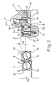
- said linear motion rolling guide unit is equipped with track rail 2 fixed on bed 1 functioning as the stationary side, and track rail 4 fixed on table 3 functioning as the moving side.
- track rail 2 and 4 are provided in the form of two sets with one set consisting of a pair of corresponding rails.
- table 3 is used as the stationary side and bed 1 is used as the moving side.
- Bed 1 has projection 1a in its center, with the right and left sides of said projection la forming mounting surfaces 1b.
- the inside surfaces of track rails 2 make contact with mounting surfaces 1b.
- Mounting surfaces 1c are formed near the right and left sides of the above-mentioned projection 1a, and mounting surfaces 2a formed in the bottom of track rails 2 make contact with these mounting surfaces 1c.
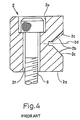
- Track surfaces 2b having roughly V-shaped cross-sections, are formed along the lengthwise direction on the outside of track rails 2. As indicated in Fig. 4, said track surfaces 2b have two flat bearing surfaces 2c mutually intersecting at an angle of, for example, 90 degrees. As is particularly clear from Fig. 4. countersunk portions 2e and threaded insertion holes 2f are concentrically formed extending perpendicular to center line 2d of the angle formed by the above-mentioned track surfaces 2b. The head and threaded portion of a fastening member in the form of bolts 6 (with hexagonal sockets) are inserted into countersunk portions 2e and threaded insertion holes 2f, respectively. These bolts 6 are screwed into bed 1 resulting in track rail 2 being fastened to bed 1. Furthermore, countersunk portions 2e are formed in the uppermost side of track rails 2.
- hanging portions 3a are formed on the right and left sides of table 3, and the inside surfaces of each of said hanging portions 3a serve as mounting surfaces 3b.
- the outside surfaces of track rails 4 then make contact with these mounting surfaces 3b.
- Mounting surfaces 3c are also formed on the inside of each of the above-mentioned hanging portions 3a on table 3, and mounting surfaces 4a formed on track rails 4 make contact with these mounting surfaces 3c.
- V-shaped cross-sectional track surfaces 4b having two intersecting flat bearing surfaces (not provided with reference numerals) are formed along the lengthwise direction on the insides of track rails 4 in the same manner as track surfaces 2b of the above-mentioned track rails 2.
- These track rails 4 and the above-mentioned track rails 2 are arranged so that the respective track surfaces 2b and 4b of each of these oppose each other.
- threaded holes 4c are formed in track rails 4, and said track rails 4 are fastened to table 3 by bolts (with hexagonal sockets) 7 that are screwed into said threaded holes 4c.
- a plurality of rollers 8, and roughly rectangular plate-shaped cage 9, which hold each of said rollers 8 while allowing to rotate freely, are juxtaposed between the above-mentioned track surfaces 2b and 4b.
- Each of rollers 8 is arranged in a row so that the central axes of rotation of adjacent rollers mutually cross. Said rollers then roll over each of the above-mentioned track surfaces 2b and 4b.
- end locking plates 10 and end screws 11 are mounted on the ends of each of track rails 2 and 4 to prevent the above-mentioned cage 9 and rollers 8 from coming out.
- pre-loading adjustment screw 12 that engages with track rail 4, is screwed into one of the hanging portions 3a of table 3.
- DE-A-31 34 313 discloses a linear motion rolling guide according to the preamble of claim 1 of the present invention. This known linear motion rolling guide is similar to the previously described prior art embodiment.
- CH-A-303 754 discloses a very flat linear motion rolling guide wherein the heads of the tightening bolts are received in countersunk holes with the upper surface of the bolt head being in the same plane as the upper surface of the track rail.
- a similar linear motion rolling guide is disclosed in DE-C-974 929 wherein the upper surface of the bolt head lies also in the same plane as the upper surface of the track rail.
- DE-A-36 38 968 discloses a linear motion rolling guide wherein the heads of the tightening bolts are received in countersunk holes which are only slightly deeper than the height of the respective bolt heads, and wherein the track rail is very thick with respect to the width of the respective bearing surface.
- bottom surfaces of the countersunk holes are located in the vicinity of the center line of the angle formed by the track surfaces.
- Figs. 5 and 6 indicate a linear motion rolling guide unit in the form of a first embodiment of the present invention. Furthermore, since said linear motion rolling guide unit has a similar constitution to the linear motion rolling guide unit of the prior art indicated in Figs. 1 through 4 with the exception of the essential components explained below, a detailed description will not be provided for the entire unit. In addition, in the explanation provided below, the same reference numerals are used for those constituent members that are the same as those of said linear motion rolling guide unit of the prior art. In addition, this applies similarly in the explanation of a forthcoming explanation of a second embodiment.
- track rail 31 fixed on bed 1 to form a pair with track rail 4 mounted on the side of table 3 is formed in the manner described below.
- this track rail 31 makes contact with the side of projection la formed on bed 1, or in other words, mounting surface 1b on its inside surface. Said track rail 31 also makes contact with mounting surface 1c formed near said mounting surface 1b with mounting surface 31a on its bottom.
- track surface 31b having a roughly V-shaped cross-section, is formed along the lengthwise direction on the outside of track rail 31.
- This track surface 31b opposes track surface 4b of the other track rail 4.
- this track surface 31b has two flat bearing surfaces 31c that mutually intersect at an angle of, for example, 90 degrees.
- countersunk portions 31e and threaded insertion holes 31f which extend perpendicular to center line 31d of the angle formed by the above-mentioned track surfaces 31b, are formed concentrically in track rail 31.
- bottom surfaces 31g of the above-mentioned countersunk portions 31e are formed so as to be positioned in the direction of said fastening on hypothetical extended surface 31h or with respect to said hypothetical extended surface 31h of the bearing surface of the two bearing surfaces 31c that form track surface 31b which is positioned in the direction of tightening of bolts 6. Furthermore, this fastening direction refers to the direction from the uppermost portion of track rail 31 towards mounting surface 31a. Due to said constitution, generation of strain in the upper track of track rail 31 due to fastening of bolts 6 is prevented and there is no narrowing of the opening angle of track surface 31b. Thus, high operating accuracy is constantly able to be obtained and sliding resistance is suppressed to a low level.
- the linear motion rolling guide unit in the form of a second embodiment of the present invention is equipped with track rail 41 fixed on bed 1 and track rail 44 fixed on table 3.
- track rail 41 fixed on bed 1 and track rail 44 fixed on table 3.
- a total of four of these track rails 41 and 44 are provided in the form of two sets with one set comprising one mutually corresponding pair each.
- the track rail 41 makes contact with projection 1a formed on bed 1, or in other words, mounting surface 1b, with its inside surface. Said track rail 41 also makes contact with mounting surface 1c formed near said mounting surface 1b with bottom mounting surface 41a.
- This track surface formed into projection 41b has two flat bearing surfaces (not provided with reference numerals) that mutually intersect at an angle of, for example, 90 degrees.
- Countersunk portions 41e and threaded insertion holes 41f extending perpendicular to center line 41d of the above-mentioned projection 41b, are formed concentrically in track rail 41.
- the heads and threaded portions of fastening members in the form of bolts 46 are inserted into each of countersunk portions 41e and threaded insertion holes 41f. These bolts 46 are screwed into bed 1 resulting in track rail 41 being fastened to bed 1.
- the other track rail 44 forming a pair with the above-mentioned track rail 41, is mounted on table 3 in the manner described below.
- the outside surface of track rail 44 makes contact with the inside surface of hanging portion 3b projecting from the right and left sides of table 3, or in other words, mounting surface 3b.
- Mounting surface 44a formed in track rail 44 makes contact with mounting surface 3c provided near said hanging portion 3b.
- track surface 44b having a roughly V-shaped cross-section, is formed along the lengthwise direction in the inside surface of track rail 44. Projection 41b of the above-mentioned track rail 41 is inserted into this V-shaped track surface 44b.
- This V-shaped track surface 44b has two flat bearing surfaces 44c that mutually intersect at an angle of, for example, 90 degrees.
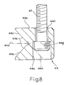
- countersunk portions 44e and threaded insertion holes 44f extending perpendicular to center line 44d of the angle formed by the above-mentioned track surfaces 44b, are formed concentrically in track rail 44.
- bottom surface 44g of the above-mentioned countersunk portion 44e is formed so as to be positioned in the direction of fastening either on hypothetical extended surface 44h or with respect to said hypothetical extended surface 44h of one of the two bearing surfaces 44c that form track surface 44b positioned in the tightening direction of bolt 47. Furthermore, this direction of fastening refers to the direction from the uppermost portion of track rail 44 towards mounting surface 44a. Due to said constitution, generation of strain in the tracks of track rail 44 due to fastening of bolts 47 is prevented and there is no narrowing of the opening angle of track surface 44b. Thus, high operating accuracy is constantly able to be obtained and sliding resistance is suppressed to a low level.
- a plurality of cylindrical rollers 48 and rectangular plate-shaped cage 49 which holds said cylindrical rollers while allowing to rotate freely, are juxtaposed between projection 41b and track surface 44b of the above-mentioned track rails 41 and 44, respectively.
- These cylindrical rollers bear the load by rolling over the track surface formed into the above-mentioned projection 41b and each of the bearing surfaces of track surface 44b.
- pre-loading adjustment screw 52 that engages with track rail 44, screws into one of the hanging portions 3a of table 3, and lock nut 53 is screwed onto said pre-loading adjustment screw 52.
- the opening angle of the track surface is not narrowed by the fastening of said fastening members thus offering the advantage of allowing high operating accuracy to be constantly obtained and sliding resistance to be suppressed to a low level.
Landscapes
- Engineering & Computer Science (AREA)
- General Engineering & Computer Science (AREA)
- Mechanical Engineering (AREA)
- Bearings For Parts Moving Linearly (AREA)
Claims (3)
- Unité compacte de guidage par roulement de déplacement linéaire, à coulissement fini, équipée de:- une paire de voies (4, 31) permettant un déplacement relatif, dans laquelle des surfaces de roulement (4b, 31b) dont la section transversale est sensiblement en forme de V, présentant deux surfaces d'appui (31c) qui se coupent, sont chacune formées suivant la direction longitudinale et agencées de manière à se faire face;- plusieurs galets (8), qui sont agencés en série entre les surfaces de roulement (4b, 31b) mentionnées plus haut de telle sorte que les axes centraux de rotation de galets adjacents se croisent mutuellement, et qui roulent sur les surfaces d'appui (31c) mentionnées plus haut;- une cage (9) qui maintient chacun des galets (8) mentionnés plus haut, tout en leur permettant de tourner librement; et- des parties fraisées (31e) et des trous d'insertion (31f) qui permettent l'insertion d'organes de fixation (6) s'étendant sensiblement perpendiculairement à la bissectrice (31d) de l'angle formé par les surfaces de roulement (4b, 31b) mentionnées plus haut, et qui sont formées concentriquement dans au moins l'un des rails de roulement (4, 31) mentionnés plus haut;dans laquelle- ledit rail de roulement au moins présent présente une surface de montage (31a) pour son montage sur un bâti prescrit,- ladite surface de roulement (31b) est formée dans le côté dudit rail de roulement (31) au moins présent, et lesdites parties fraisées (31e) sont formées dans le côté opposé à la surface de montage, et- ladite direction d'insertion des organes de fixation (6) est la direction s'étendant du côté opposé vers ladite surface de montage (31a),caractérisée en ce que- les surfaces de fond (31g) des parties fraisées (31e) mentionnées plus haut sont situées sur ou, lorsque l'on regarde dans la direction d'insertion, au-delà d'une surface imaginaire prolongeant la surface d'appui du côté plus proche de la surface de montage, et- la profondeur de la partie fraisée correspondante est sensiblement supérieure à la hauteur de l'organe de fixation au-dessus de la surface de base de la partie fraisée, de manière à empêcher la création de contraintes dues à la fixation d'organes de fixation (6), dans la voie du rail de roulement (31) au moins présent, à distance de la surface de montage, et à ce qu'il n'existe pas de rétrécissement de l'angle d'ouverture de la surface de roulement (31b).
- Unité compacte de guidage par roulement de déplacement linéaire, à coulissement fini, comprenant:- un premier rail de roulement (44) et un deuxième rail de roulement (41),dans laquelle- ledit premier rail de roulement (44) comporte une surface de roulement (44b) présentant deux surfaces d'appui (44c) qui se coupent et une section transversale sensiblement en forme de V,- ledit deuxième rail de roulement (41) comporte une surface de roulement configurée en forme de saillie (41b),- ladite forme en V et ladite saillie (41b) sont formées suivant une direction longitudinale, et- ladite saillie (41b) est agencée de manière à être insérée dans ladite forme en V;et comportant:- plusieurs galets (48) agencés entre ladite forme en V et ladite saillie, et qui roulent sur lesdites surfaces d'appui; et- des parties fraisées (44e) et des trous d'insertion (44f) qui permettent l'insertion d'organes de fixation (47) dans une direction sensiblement perpendiculaire à une bissectrice d'un angle formé par ladite forme en V, et qui sont formées concentriquement dans au moins ledit premier rail de roulement (44) présentant ladite forme en V;caractérisée en ce que- les surfaces de fond desdites parties fraisées (44e) sont situées sur ou, lorsqu'on les regarde dans la direction d'insertion, au-delà d'une surface imaginaire prolongeant la surface d'appui, plus proche d'une surface de montage dudit premier rail de roulement (44), pour le montage sur un bâti prescrit, et- la profondeur de la partie fraisée correspondante est essentiellement supérieure à la hauteur de l'organe de fixation au-dessus de la surface de fond de la partie fraisée, de manière à empêcher la création de contraintes dues à la fixation d'organes de fixation (47), dans la piste de roulement dudit premier rail de roulement (44), à distance de la surface de montage, et à ce qu'il n'existe pas de rétrécissement de l'angle d'ouverture de la surface de roulement (44b).
- Unité de guidage par roulement d'un déplacement linéaire selon la revendication 2, dans laquelle:- le premier rail de roulement (44) présente une surface opposée à la surface de montage,- ladite surface de roulement dudit premier rail de roulement (44) et des parties fraisées sont formées respectivement dans le côté et dans le côté opposé dudit premier rail de roulement, et ladite direction d'insertion est la direction allant dudit côté opposé vers ladite surface de montage.
Applications Claiming Priority (2)
| Application Number | Priority Date | Filing Date | Title |
|---|---|---|---|
| JP1992033924U JP2541519Y2 (ja) | 1992-04-24 | 1992-04-24 | 直動転がり案内ユニット |
| JP33924/92U | 1992-04-24 |
Publications (2)
| Publication Number | Publication Date |
|---|---|
| EP0567032A1 EP0567032A1 (fr) | 1993-10-27 |
| EP0567032B1 true EP0567032B1 (fr) | 1997-09-10 |
Family
ID=12400072
Family Applications (1)
| Application Number | Title | Priority Date | Filing Date |
|---|---|---|---|
| EP93106296A Expired - Lifetime EP0567032B1 (fr) | 1992-04-24 | 1993-04-19 | Unité de guidage pour mouvement de roulement linéaire |
Country Status (4)
| Country | Link |
|---|---|
| US (1) | US5513916A (fr) |
| EP (1) | EP0567032B1 (fr) |
| JP (1) | JP2541519Y2 (fr) |
| DE (1) | DE69313708T2 (fr) |
Families Citing this family (17)
| Publication number | Priority date | Publication date | Assignee | Title |
|---|---|---|---|---|
| JPH07279957A (ja) * | 1994-04-05 | 1995-10-27 | Nippon Seiko Kk | リニアガイド装置の案内レール |
| IT234178Y1 (it) * | 1994-10-25 | 2000-02-23 | Cavagna Elio Srl | Carrello perfezionato per unita' di taglio |
| JP3455016B2 (ja) * | 1996-06-20 | 2003-10-06 | シグマ光機株式会社 | 直線運動ステージの鋼球ガイド溝加工方法およびその装置 |
| US20030127812A1 (en) * | 2002-01-04 | 2003-07-10 | Charles Mehrmann | Bi-directional sliding board |
| US20060000024A1 (en) * | 2002-11-18 | 2006-01-05 | Mcguire Sheri L | Mattress having a flammable core and a nonwoven cellulose flame retardant fabric |
| JP2004028329A (ja) * | 2003-03-28 | 2004-01-29 | Sigma Koki Kk | 直線運動ステージ |
| JP4295576B2 (ja) * | 2003-08-07 | 2009-07-15 | 日本トムソン株式会社 | 直動案内ユニット |
| US20070230838A1 (en) * | 2006-03-28 | 2007-10-04 | Steven Fulton | Compliant rail linear guide |
| US20080304774A1 (en) * | 2007-06-11 | 2008-12-11 | Quality Vision International, Inc. | Method and apparatus for pneumatic preloading of linear bearing assemblies |
| US8608383B2 (en) * | 2008-10-29 | 2013-12-17 | Bishop-Wisecarver Corporation | System for holding a linear motion guide track to a support base and method therefor |
| US8491193B2 (en) * | 2008-10-29 | 2013-07-23 | Bishop-Wisecarver Corporation | Press fitting interface for holding a track to an extrusion without the use of fasteners; and methods for using the same |
| US8434946B2 (en) * | 2008-10-29 | 2013-05-07 | Bishop-Wisecarver Corporation | System, method, and apparatus for holding a track to a base |
| JP2012193859A (ja) * | 2012-07-10 | 2012-10-11 | Thk Co Ltd | ベアリング |
| JP6815107B2 (ja) * | 2016-07-06 | 2021-01-20 | 日本トムソン株式会社 | 保持器ずれ防止機構を備えた有限直動案内ユニット |
| TWI703276B (zh) * | 2018-05-31 | 2020-09-01 | 全研科技有限公司 | 高荷重滑軌結構 |
| TWI703277B (zh) * | 2018-05-31 | 2020-09-01 | 全研科技有限公司 | 高荷重多軸調整裝置 |
| CN110081078B (zh) * | 2019-04-28 | 2024-04-19 | 广西科技大学 | 一种用于减重机构与悬吊机构间的连接装置 |
Citations (2)
| Publication number | Priority date | Publication date | Assignee | Title |
|---|---|---|---|---|
| CH303754A (de) * | 1952-03-05 | 1954-12-15 | Arenco Ab | Schlittenführung. |
| DE974929C (de) * | 1952-03-28 | 1961-05-31 | Skf Svenska Kullagerfab Ab | Lager fuer Maschinenschlitten mit in endloser Folge hintereinander angeordneten Waelzkoerpern |
Family Cites Families (5)
| Publication number | Priority date | Publication date | Assignee | Title |
|---|---|---|---|---|
| US2785934A (en) * | 1952-03-28 | 1957-03-19 | Skf Ind Inc | Bearing for the carriages of machine tools and the like |
| DD262343A3 (de) * | 1986-07-29 | 1988-11-30 | Werkzeugmasch Okt Veb | Schraegprisma - waelzlaengsfuehrung |
| DE3629173A1 (de) * | 1986-08-28 | 1988-03-10 | Kabus Horst Maschf | Kreuzrollenlager |
| DE3824191A1 (de) * | 1988-07-16 | 1990-01-18 | Werner Jacob | Umlauffuehrung fuer waelzkoerper |
| DE4217663C2 (de) * | 1991-05-31 | 2001-10-04 | Hydrel Ag Romanshorn | Lineare Führungsvorrichtung |
-
1992
- 1992-04-24 JP JP1992033924U patent/JP2541519Y2/ja not_active Expired - Lifetime
-
1993
- 1993-04-19 EP EP93106296A patent/EP0567032B1/fr not_active Expired - Lifetime
- 1993-04-19 DE DE69313708T patent/DE69313708T2/de not_active Expired - Lifetime
-
1994
- 1994-08-24 US US08/294,032 patent/US5513916A/en not_active Expired - Lifetime
Patent Citations (2)
| Publication number | Priority date | Publication date | Assignee | Title |
|---|---|---|---|---|
| CH303754A (de) * | 1952-03-05 | 1954-12-15 | Arenco Ab | Schlittenführung. |
| DE974929C (de) * | 1952-03-28 | 1961-05-31 | Skf Svenska Kullagerfab Ab | Lager fuer Maschinenschlitten mit in endloser Folge hintereinander angeordneten Waelzkoerpern |
Non-Patent Citations (7)
| Title |
|---|
| Brochure: HYDREL-Flachkäfigführungen, INA, Art.Nr.191529-0/TPI 61 * |
| CH-A- 303 754 * |
| DE-A- 3 134 313 * |
| DE-A- 3 638 968 * |
| DE-A- 4 107 009 * |
| DE-C- 974 929 * |
| M. Klein, Einführung in die DIN-Normen, B.G. Teubner, Stutgart, 6th. ed. 1970, pages 495, 496, 504, 505 * |
Also Published As
| Publication number | Publication date |
|---|---|
| US5513916A (en) | 1996-05-07 |
| DE69313708T2 (de) | 1998-02-12 |
| JPH0586021U (ja) | 1993-11-19 |
| JP2541519Y2 (ja) | 1997-07-16 |
| DE69313708D1 (de) | 1997-10-16 |
| EP0567032A1 (fr) | 1993-10-27 |
Similar Documents
| Publication | Publication Date | Title |
|---|---|---|
| US5513916A (en) | Linear motion rolling guide unit having mounting arrangement adapted to eliminate track deformation | |
| US5487609A (en) | Slide unit for linear motion | |
| EP0653574A2 (fr) | Chariot coulissant avec positionnement réglable des pistes de roulement | |
| DE2743835A1 (de) | Kugelfuehrung | |
| JPH0753866Y2 (ja) | 直動案内ユニット | |
| KR890000319B1 (ko) | 직선접동용 로울러베어링 | |
| US4867579A (en) | Widely adjustable sliding unit for operating machines | |
| EP0594209B1 (fr) | Unité de guidage pour mouvement de roulement linéaire | |
| DE3447778A1 (de) | Lineares gleitrollenlager | |
| US4433876A (en) | Rolling bearing for linear motion | |
| US4611861A (en) | Linear motion rolling contact bearing having a double row runway | |
| DE3705372C2 (fr) | ||
| JP2553973B2 (ja) | ボールねじ付直線運動案内装置およびボールねじの予圧付与方法 | |
| US5172982A (en) | Linear motion rolling guide unit | |
| US5375931A (en) | Linear motion bearing | |
| US5393144A (en) | Linear motion guide unit | |
| US4921167A (en) | Carrier section including flange member for connection to a guide rail | |
| US5388914A (en) | Linear motion rolling guide unit | |
| US5137371A (en) | Linear guide table system | |
| GB2142097A (en) | Linear slide roller bearing unit | |
| JPH0818209B2 (ja) | テーブル移送装置 | |
| US4592531A (en) | Linear switch positioning device | |
| JPS6224652B2 (fr) | ||
| KR20020045459A (ko) | 리니어 모션 가이드의 캐리어 | |
| JPH082499Y2 (ja) | 直線運動用ベアリングの軌道台の取付構造 |
Legal Events
| Date | Code | Title | Description |
|---|---|---|---|
| PUAI | Public reference made under article 153(3) epc to a published international application that has entered the european phase |
Free format text: ORIGINAL CODE: 0009012 |
|
| AK | Designated contracting states |
Kind code of ref document: A1 Designated state(s): DE GB |
|
| 17P | Request for examination filed |
Effective date: 19940113 |
|
| 17Q | First examination report despatched |
Effective date: 19941206 |
|
| GRAG | Despatch of communication of intention to grant |
Free format text: ORIGINAL CODE: EPIDOS AGRA |
|
| GRAH | Despatch of communication of intention to grant a patent |
Free format text: ORIGINAL CODE: EPIDOS IGRA |
|
| GRAH | Despatch of communication of intention to grant a patent |
Free format text: ORIGINAL CODE: EPIDOS IGRA |
|
| GRAA | (expected) grant |
Free format text: ORIGINAL CODE: 0009210 |
|
| AK | Designated contracting states |
Kind code of ref document: B1 Designated state(s): DE GB |
|
| REF | Corresponds to: |
Ref document number: 69313708 Country of ref document: DE Date of ref document: 19971016 |
|
| PLBE | No opposition filed within time limit |
Free format text: ORIGINAL CODE: 0009261 |
|
| 26N | No opposition filed | ||
| REG | Reference to a national code |
Ref country code: GB Ref legal event code: IF02 |
|
| PGFP | Annual fee paid to national office [announced via postgrant information from national office to epo] |
Ref country code: GB Payment date: 20120328 Year of fee payment: 20 |
|
| PGFP | Annual fee paid to national office [announced via postgrant information from national office to epo] |
Ref country code: DE Payment date: 20120425 Year of fee payment: 20 |
|
| REG | Reference to a national code |
Ref country code: DE Ref legal event code: R071 Ref document number: 69313708 Country of ref document: DE |
|
| REG | Reference to a national code |
Ref country code: GB Ref legal event code: PE20 Expiry date: 20130418 |
|
| PG25 | Lapsed in a contracting state [announced via postgrant information from national office to epo] |
Ref country code: DE Free format text: LAPSE BECAUSE OF EXPIRATION OF PROTECTION Effective date: 20130420 Ref country code: GB Free format text: LAPSE BECAUSE OF EXPIRATION OF PROTECTION Effective date: 20130418 |