EP0567080A1 - Optische Informationsspeicherplatte zur Verwendung in elektronischen Artikelüberwachungssystemen - Google Patents
Optische Informationsspeicherplatte zur Verwendung in elektronischen Artikelüberwachungssystemen Download PDFInfo
- Publication number
- EP0567080A1 EP0567080A1 EP93106403A EP93106403A EP0567080A1 EP 0567080 A1 EP0567080 A1 EP 0567080A1 EP 93106403 A EP93106403 A EP 93106403A EP 93106403 A EP93106403 A EP 93106403A EP 0567080 A1 EP0567080 A1 EP 0567080A1
- Authority
- EP
- European Patent Office
- Prior art keywords
- marker
- disk
- generally
- magnetic
- annulus
- Prior art date
- Legal status (The legal status is an assumption and is not a legal conclusion. Google has not performed a legal analysis and makes no representation as to the accuracy of the status listed.)
- Granted
Links
Images
Classifications
-
- G—PHYSICS
- G11—INFORMATION STORAGE
- G11B—INFORMATION STORAGE BASED ON RELATIVE MOVEMENT BETWEEN RECORD CARRIER AND TRANSDUCER
- G11B7/00—Recording or reproducing by optical means, e.g. recording using a thermal beam of optical radiation by modifying optical properties or the physical structure, reproducing using an optical beam at lower power by sensing optical properties; Record carriers therefor
-
- G—PHYSICS
- G11—INFORMATION STORAGE
- G11B—INFORMATION STORAGE BASED ON RELATIVE MOVEMENT BETWEEN RECORD CARRIER AND TRANSDUCER
- G11B23/00—Record carriers not specific to the method of recording or reproducing; Accessories, e.g. containers, specially adapted for co-operation with the recording or reproducing apparatus ; Intermediate mediums; Apparatus or processes specially adapted for their manufacture
- G11B23/28—Indicating or preventing prior or unauthorised use, e.g. cassettes with sealing or locking means, write-protect devices for discs
- G11B23/286—Antitheft arrangements, e.g. Electronic Article Surveillance [EAS] tags
-
- G—PHYSICS
- G08—SIGNALLING
- G08B—SIGNALLING SYSTEMS, e.g. PERSONAL CALLING SYSTEMS; ORDER TELEGRAPHS; ALARM SYSTEMS
- G08B13/00—Burglar, theft or intruder alarms
- G08B13/22—Electrical actuation
- G08B13/24—Electrical actuation by interference with electromagnetic field distribution
- G08B13/2402—Electronic Article Surveillance [EAS], i.e. systems using tags for detecting removal of a tagged item from a secure area, e.g. tags for detecting shoplifting
- G08B13/2405—Electronic Article Surveillance [EAS], i.e. systems using tags for detecting removal of a tagged item from a secure area, e.g. tags for detecting shoplifting characterised by the tag technology used
- G08B13/2408—Electronic Article Surveillance [EAS], i.e. systems using tags for detecting removal of a tagged item from a secure area, e.g. tags for detecting shoplifting characterised by the tag technology used using ferromagnetic tags
-
- G—PHYSICS
- G08—SIGNALLING
- G08B—SIGNALLING SYSTEMS, e.g. PERSONAL CALLING SYSTEMS; ORDER TELEGRAPHS; ALARM SYSTEMS
- G08B13/00—Burglar, theft or intruder alarms
- G08B13/22—Electrical actuation
- G08B13/24—Electrical actuation by interference with electromagnetic field distribution
- G08B13/2402—Electronic Article Surveillance [EAS], i.e. systems using tags for detecting removal of a tagged item from a secure area, e.g. tags for detecting shoplifting
- G08B13/2428—Tag details
- G08B13/2434—Tag housing and attachment details
-
- G—PHYSICS
- G08—SIGNALLING
- G08B—SIGNALLING SYSTEMS, e.g. PERSONAL CALLING SYSTEMS; ORDER TELEGRAPHS; ALARM SYSTEMS
- G08B13/00—Burglar, theft or intruder alarms
- G08B13/22—Electrical actuation
- G08B13/24—Electrical actuation by interference with electromagnetic field distribution
- G08B13/2402—Electronic Article Surveillance [EAS], i.e. systems using tags for detecting removal of a tagged item from a secure area, e.g. tags for detecting shoplifting
- G08B13/2428—Tag details
- G08B13/2437—Tag layered structure, processes for making layered tags
- G08B13/2442—Tag materials and material properties thereof, e.g. magnetic material details
-
- G—PHYSICS
- G08—SIGNALLING
- G08B—SIGNALLING SYSTEMS, e.g. PERSONAL CALLING SYSTEMS; ORDER TELEGRAPHS; ALARM SYSTEMS
- G08B13/00—Burglar, theft or intruder alarms
- G08B13/22—Electrical actuation
- G08B13/24—Electrical actuation by interference with electromagnetic field distribution
- G08B13/2402—Electronic Article Surveillance [EAS], i.e. systems using tags for detecting removal of a tagged item from a secure area, e.g. tags for detecting shoplifting
- G08B13/2428—Tag details
- G08B13/2437—Tag layered structure, processes for making layered tags
- G08B13/2445—Tag integrated into item to be protected, e.g. source tagging
-
- G—PHYSICS
- G11—INFORMATION STORAGE
- G11B—INFORMATION STORAGE BASED ON RELATIVE MOVEMENT BETWEEN RECORD CARRIER AND TRANSDUCER
- G11B23/00—Record carriers not specific to the method of recording or reproducing; Accessories, e.g. containers, specially adapted for co-operation with the recording or reproducing apparatus ; Intermediate mediums; Apparatus or processes specially adapted for their manufacture
- G11B23/0014—Record carriers not specific to the method of recording or reproducing; Accessories, e.g. containers, specially adapted for co-operation with the recording or reproducing apparatus ; Intermediate mediums; Apparatus or processes specially adapted for their manufacture record carriers not specifically of filamentary or web form
- G11B23/0021—Record carriers not specific to the method of recording or reproducing; Accessories, e.g. containers, specially adapted for co-operation with the recording or reproducing apparatus ; Intermediate mediums; Apparatus or processes specially adapted for their manufacture record carriers not specifically of filamentary or web form discs
- G11B23/0028—Details
- G11B23/0035—Details means incorporated in the disc, e.g. hub, to enable its guiding, loading or driving
- G11B23/0042—Details means incorporated in the disc, e.g. hub, to enable its guiding, loading or driving with provision for auxiliary features
-
- G—PHYSICS
- G11—INFORMATION STORAGE
- G11B—INFORMATION STORAGE BASED ON RELATIVE MOVEMENT BETWEEN RECORD CARRIER AND TRANSDUCER
- G11B7/00—Recording or reproducing by optical means, e.g. recording using a thermal beam of optical radiation by modifying optical properties or the physical structure, reproducing using an optical beam at lower power by sensing optical properties; Record carriers therefor
- G11B7/24—Record carriers characterised by shape, structure or physical properties, or by the selection of the material
Definitions
- This invention relates in general to data storage disks for encoding data in optically detectable, generally concentric data tracks.
- it relates to compact optical information storage disks especially adapted for use with an electronic article surveillance (EAS) system.
- EAS electronic article surveillance
- the now familiar compact disk preserves information as a series of microscopic pits and smooth areas, oriented in concentric circular or helical tracks, on the otherwise smooth, planar surface of an annular disk.
- Recorded information is read from a compact disk by directing a focused laser beam along the recorded tracks, and detecting variations in the intensity of the laser beam as it encounters the microscopic pits and smooth areas on the disk.
- the coherence and relatively short wavelength of laser radiation enables large volumes of information to be written onto very small spaces of a recording medium.
- the recording industry has for the last ten years packaged the five inch in diameter prerecorded compact disks in six inch (15 cm) by twelve inch (30 cm) cardboard boxes known in the industry as "longboxes.”
- the longbox is easily propped up in display bins alongside traditional vinyl LPs in music store display bins. More importantly, however, the bulk of the longbox makes it difficult for a shoplifter to hide a prerecorded compact disk under a coat or in a purse and walk out of a music store without paying.
- Electronic article surveillance systems for monitoring the egress of sensitive objects from controlled spaces are well known, and have been used alone and along with the longbox packaging technique for controlling the unauthorized taking of compact disks.
- Markers formed from a piece of high permeability magnetic material can be placed on the packaging for the disk.
- Spaced apart detection panels are then placed across the access points to and from the store, library or other repository for the monitored compact disks.
- the panels include field coils and detector coils for producing a magnetic field across the access point that can detect the passage of a marker between the panels. If a person attempts to carry a compact disk through the magnetic field presented by the panels without first deactivating the marker on the disk packaging, the presence of the marker will be detected and an alarm initiated.
- U. S. Patent No. 4,710,754 discloses a multi-directional EAS marker especially designed for its compact dimensions.
- the marker disclosed in the '754 patent is comprised of a high permeability, low coercive force, generally planar magnetic responder material that includes at least two narrow regions defining switching sections, and adjacent, wider, flux collector sections. The juxtaposition of the narrow switching sections with the flux collector sections causes the flux to be highly concentrated in the switching sections. The high concentration of flux lines in the switching sections produces high frequency harmonics when passed through an alternating magnetic field, allowing the presence of the marker in the field to be detected.
- the marker is conveniently made dual status, i.e., reversibly deactivatable and reactivatable, by including a piece of remanently magnetizable material adjacent each of the switching sections.
- the remanently magnetizable material when magnetized, biases the adjacent switching section to either keep the magnetization therein from reversing when in an alternating interrogation field, or at least altering the response of the marker in the field. In either case, readily distinguishably different signals are produced by the marker in an interrogation field depending on whether the remanently magnetizable material is magnetized or demagnetized.
- U. S. Patent No. 4,967,185 discloses a multi-directional, dual-status EAS marker also designed for its compact dimensions.
- the marker disclosed in the '185 patent discloses a marker that includes a continuous uninterrupted sheet of remanently magnetizable material overlying a sheet of responder material similar to that disclosed in the '754 patent.
- the response of the marker within an alternating magnetic field can be discernably altered by selectively magnetizing and demagnetizing the continuous sheet of remanently magnetizable material prior to introducing the marker into the field.
- the markers disclosed in the above noted prior art can be attached to the packaging for a compact disk. Problems arise, however, when attempting to attach prior art markers directly to the surface of a compact disk. Rotation of the compact disk is required to read information from the disk, and the disk must accordingly be inherently balanced. An EAS marker, applied directly to a compact disk, therefor, would preferably be somehow concentrically mounted on the disk without imbalancing the disk. Prior art EAS markers, however, are not inherently balanced. Moreover, conventional compact disks include a centered aperture that must be maintained clear of obstructions, and the preferred prior art dual status EAS markers include a continuous sheet of magnetic material, such that the marker cannot be concentrically mounted to the surface of a compact disk without obstructing the disk aperture.
- U. S. Patent No. 4,709,813 proposed an anti-theft device for compact disks that overcame the inability to directly apply an EAS marker to the surface of a compact disk.
- the '813 patent discloses a detachable locking plate with an EAS marker carried on the internal face of the plate that can be selectively locked to the "jewelry box" for a compact disk.
- the compact disk is physically locked in the box leg by the plate.
- a clerk or other authorized person can remove the plate with the use of a keyed release tool at the time of payment.
- the compact, optical information storage disk in accordance with the present invention is especially adapted for tamper-proof monitoring by an electronic article surveillance system.
- the compact disk hereof includes a generally planar, annular first disk surface and an opposed, generally annular second disk surface oriented generally parallel to the first disk surface, a plurality of generally concentric data tracks on at least one of the disk surfaces, a centered aperture and a generally annular magnetic marker concentrically oriented about the centered aperture.
- the marker is preferably adhered to the bottom of a grooved recess presented by one of the disk surfaces, and is thereafter immovably retained in the recess by a coating covering the disk surface.
- the EAS marker hereof includes a first annular member formed from a high permeability, low coercive force ferromagnetic material having a plurality of magnetic switching areas into which flux collected from adjacent areas is concentrated, thereby enabling a characteristic, readily distinguishable response to be created upon reversal of the magnetic state within at least one switching area when the marker is placed within an alternating magnetic field forming an interrogation zone.
- the width of the first annular member is restricted at least two locations positioned approximately at ninety degrees with respect to each other about the annulus to present at least two narrow switching regions alternating with wider flux collecting regions.
- the generally orthogonal relative orientation of the switching sections provides for multi-directional detection of the EAS marker in the alternating magnetic interrogation field.
- the marker further includes a second annulus member overlying the first member, and formed from a relatively high coercive force ferromagnetic material which, when magnetized, for example, in a single, linear direction, notwithstanding the annular shape of the member, alters the characteristic response of the marker when in the interrogation zone from the response resulting when the second member is demagnetized, thereby providing for the selective activation and deactivation of the EAS marker.
- the optical information storage disks hereof are designed to be stored in an access controlled space, with entrance and egress to the space directed only through the magnetic field established by the panels of an electronic article surveillance system. Passage of a disk through the panels will initiate an alarm, unless either the marker or the magnetic field is deactivated.
- the magnetic markers of the security cartridges are desirably made essentially tamper proof by applying a sealing compound, such as a lacquer coating, over the marker on the surface of the disk. Other layers or sealing techniques may also be employed to prevent removal.
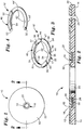
- an optical information storage disk 10 in accordance with the present invention broadly includes a generally planar, annular first disk surface 12, an opposed, annular second disk surface 14 oriented generally parallel to the first disk surface 12, and an annular magnetic marker 16 carried within an annular groove 18 in the first disk surface 12. Centered aperture 20 and circular peripheral rim 22 extend between the first surface 12 and second surface 14. The magnetic marker 16 is concentrically oriented about the centered aperture 20.
- Information tracks 24 are made up of microscopic pits and smooth areas on the disk first surface 12.
- the tracks 24 can be either circular or helical and are concentrically oriented about the centered aperture 20.
- the annular groove 18 presents a generally cylindrical groove inner wall 26, an opposed generally cylindrical groove outer wall 28, and a generally annular bottom wall 30 extending between the groove inner wall 26 and outer wall 28.
- the groove inner wall 26 and outer wall 28 are both oriented generally normal to the first disk surface 12.
- the groove bottom wall 30 is recessed from, and oriented generally parallel to, the first disk surface 12.
- Magnetic marker 16 includes a first annulus member 32 formed from a high permeability, low coercive force ferromagnetic material such as permalloy, supermalloy, or the like.
- the annulus member 32 has an upper surface 34, a lower surface 36, an inner peripheral rim 38, and an outer peripheral rim 40.
- the notches 42 are formed on the internal peripheral rim 38 of the annulus 32.
- the notches 42 are spaced apart at approximately ninety degree intervals along the rim 40.
- Four external notches 44 are formed in the outer peripheral rim 40 of the annulus member 32 in opposed relationship with the internal notches 42.
- the opposed pairs of notches 42, 44 define regions of reduced cross sectional area 46 along the annulus 32. Flux collection regions 47 are created between the areas 46.
- a second annulus member 48 is adhesively coupled to, and is substantially coextensive with, the first annulus member 32.
- the second annulus member 48 is formed from a sheet of relatively high coercive force ferromagnetic material such vicalloy, magnetic stainless steel, Chromendur II, or the like.
- the annulus member 48 includes an upper surface 50, an opposed, lower surface 52 adhesively bonded to the upper surface 34 of the first annulus member 32, an inner peripheral rim 54 generally co-extensive with the inner rim 38 of the first annulus member 38, and an outer rim 56 co-extensive with the outer rim 40 of the first annulus member 32.
- the inner rim 38 of the first annulus member 32 and the inner rim 54 of the second annulus member 48 present a marker inner rim 58.
- the groove inner diameter presented by groove inner wall 26 is matched to the inner diameter presented by marker rim 58 such that the marker 16 is self-centered about the centered aperture 20 of disk 10 by the engagement of the inner rim 58 of marker 16 with the groove inner wall 26, while avoiding force fitting the marker, which could place mechanical stress on the marker.
- the outer rim 40 of first annulus member 32 and outer rim 56 of annulus member 48 define a marker outer rim 60.
- the groove outer diameter presented by groove outer wall 28 is similarly matched to the outer diameter of marker 16 presented by marker outer rim 60 such that the marker 16 is also self-centered about the disk centered aperture 20 by engagement of the marker outer peripheral rim 60 with the groove outer wall 28.
- the magnetic marker 16 can be retained within the groove 18 by an adhesive bond applied between the lower surface 34 of annulus member 32 and the groove bottom wall 30.
- a coating 62 such as a lacquer finish, applied to and carried by the first disk surface 12 is received within the groove 18, and immovably positions the magnetic marker 16 within the groove 18.
- FIG. 4 An alternate embodiment of the marker 16' is depicted in Figure 4.
- the marker 16' is similar in many respects to the marker 16, and identical features between the two markers are annotated with identical numbers in the drawings, and similar but not identical features are indicated in Figure 4 with primed (') numbers.
- the switching sections of the marker 16' are not created by physically removing material from the first annulus member 32'. Rather, the "notches" 42', 44' are formed by physically striking the annulus 32' at the points where the "notches" 42, 44 are desired, or by otherwise work hardening the annulus 32' at the desired points. In this way, the permeability of the material at those points is lowered so that the material can no longer magnetically reverse rapidly enough to create a characteristic response.
- the marker 16 can be magnetically switched between a first state wherein it is responsive to a magnetic interrogation field to initiate an alarm as it is passed through the field, and a second state wherein it is unresponsive to the interrogation field.
- the marker 16 is switched between an active and deactive state by uniformly magnetizing and demagnetizing the second annulus member 48 of the marker 16. More particularly, the marker 16 is reliably switched from a first, active state into a second, deactivated state, by substantially uniformly magnetizing the magnetizable member 48 so as to exhibit a first magnetic polarity along one end of the member 48 and an opposite polarity at the opposite end of the member 48. This essentially linear polarization is opposed to the generally annular physical shape of the member 48. It will be appreciated that the marker 16, although of relatively small size, provides a readily distinguishable response because of the presence of flux collector regions 47 presented by the pairs of opposed notches 42, 44 of the first annulus member 32 of marker 16.
- the optical information storage disk 10 can be kept in an access controlled space, such as the display space of a retail store having entrance and egress to the space directed only through the magnetic field established by the panels of an electronic article surveillance system.
- the disks 10 would be stored with their magnetic markers 16 in the active state such that removal of a disk from the store, through the magnetic field, would set off an alarm.
- the clerk Upon proper check out of a disk 10 with a clerk, however, the clerk would deactivate the marker 16 such that its passage through the magnetic field would not initiate an alarm.
- the coating 62 effectively immovably seals the marker 16 within the groove 18 without hindering the readability of the data tracks 24 on the disk 10, since it would be difficult or impossible to remove the marker 16 without damaging the disk. Excess packaging techniques, such as use of the "longbox,” can accordingly be dispensed with, without undesirably increasing the chance of unauthorized removal of a disk from a controlled space.
- the marker 16 (and the alternative embodiment of the marker 16') disclosed herein has been especially adapted for use with compact disks, it will be appreciated that the unique shape and magnetic orientation of the marker 16 make it adaptable to other applications. For instance, the small size and annular shape of the marker 16 make it ideal for insertion into the cap of a container for pharmaceuticals, thereby providing for EAS monitoring of heretofore pilferable prescription and nonprescription drugs.
Landscapes
- Physics & Mathematics (AREA)
- Engineering & Computer Science (AREA)
- Computer Security & Cryptography (AREA)
- Automation & Control Theory (AREA)
- Electromagnetism (AREA)
- General Physics & Mathematics (AREA)
- Burglar Alarm Systems (AREA)
Applications Claiming Priority (2)
| Application Number | Priority Date | Filing Date | Title |
|---|---|---|---|
| US07/872,151 US5347508A (en) | 1992-04-22 | 1992-04-22 | Optical information storage disk for use with electronic article surveillance systems |
| US872151 | 2001-05-31 |
Publications (2)
| Publication Number | Publication Date |
|---|---|
| EP0567080A1 true EP0567080A1 (de) | 1993-10-27 |
| EP0567080B1 EP0567080B1 (de) | 1998-12-16 |
Family
ID=25358951
Family Applications (1)
| Application Number | Title | Priority Date | Filing Date |
|---|---|---|---|
| EP93106403A Expired - Lifetime EP0567080B1 (de) | 1992-04-22 | 1993-04-20 | Optische Informationsspeicherplatte zur Verwendung in elektronischen Artikelüberwachungssystemen |
Country Status (7)
| Country | Link |
|---|---|
| US (1) | US5347508A (de) |
| EP (1) | EP0567080B1 (de) |
| JP (1) | JP3332461B2 (de) |
| KR (1) | KR100276576B1 (de) |
| AU (1) | AU662607B2 (de) |
| CA (1) | CA2092358C (de) |
| DE (1) | DE69322540T2 (de) |
Cited By (9)
| Publication number | Priority date | Publication date | Assignee | Title |
|---|---|---|---|---|
| EP0704828A1 (de) * | 1994-09-28 | 1996-04-03 | Sensormatic Electronics Corporation | Magnetomechanische, in Waren oder Warenverpackung integrierte EAS-Komponenten |
| EP0732691A1 (de) * | 1995-03-16 | 1996-09-18 | Kabushiki Kaisha Toshiba | Struktur einer optischen Scheibe sowie Verfahren und Vorrichtung zu deren Herstellung |
| EP0789339A3 (de) * | 1996-02-06 | 1998-06-03 | Meto International GmbH | Sicherungselement für die elektronische Artikelsicherung |
| WO1998047139A3 (de) * | 1997-04-11 | 1999-02-11 | Walter Schlutius | Verfahren und vorrichtung zum ausrichten einer mit einem aufdruck versehenen datenträgerplatte sowie entsprechende datenträgerplatte |
| WO1999010888A1 (en) * | 1997-08-27 | 1999-03-04 | Valmark Industries, Inc. | Write-protect component for re-writable compact discs |
| NL1010200C2 (nl) * | 1998-09-28 | 2000-04-03 | Od & Me Bv | Optische registratiedrager. |
| EP1030303A3 (de) * | 1999-02-18 | 2000-10-18 | PERSONAL VIDEO ITALIA di Battilani Giancarlo | Plattenförmiger Aufzeichnungsträger mit kreisförmigem Identifikationskode |
| GB2377920A (en) * | 2001-07-25 | 2003-01-29 | Entertainment Uk Ltd | Cover and security tag fixed directly to an optical disc |
| FR2883405A1 (fr) * | 2005-03-15 | 2006-09-22 | Digital Valley | Systeme de securite pour dvd |
Families Citing this family (47)
| Publication number | Priority date | Publication date | Assignee | Title |
|---|---|---|---|---|
| US5699047A (en) * | 1996-01-19 | 1997-12-16 | Minnesota Mining And Manufacturing Co. | Electronic article surveillance markers for direct application to optically recorded media |
| US5899886A (en) * | 1997-07-07 | 1999-05-04 | Cosme; Edgar Z. | Puncture safe needle assembly |
| US5940362A (en) * | 1996-08-19 | 1999-08-17 | Sensormatic Electronics Corporation | Disc device having a magnetic layer overweighing the information signal pattern for electronic article surveillance |
| US6608561B2 (en) * | 1998-05-19 | 2003-08-19 | Meat Processing Service Corp., Inc. | Method for making a radio frequency identification device |
| WO2000000348A1 (en) * | 1998-06-29 | 2000-01-06 | Recording Industry Association Of America | Security marking system and method for minimizing pirating of data on data media |
| US6199309B1 (en) * | 1998-10-06 | 2001-03-13 | Contempo Card Company, Inc. | Merchandising markers accomodating anti-theft sensor |
| US6525661B2 (en) | 1999-02-26 | 2003-02-25 | 3M Innovative Properties Company | Electronic article surveillance markers for optically recorded media |
| US7178106B2 (en) * | 1999-04-21 | 2007-02-13 | Sonic Solutions, A California Corporation | Presentation of media content from multiple media sources |
| US7448021B1 (en) | 2000-07-24 | 2008-11-04 | Sonic Solutions, A California Corporation | Software engine for combining video or audio content with programmatic content |
| US6405203B1 (en) * | 1999-04-21 | 2002-06-11 | Research Investment Network, Inc. | Method and program product for preventing unauthorized users from using the content of an electronic storage medium |
| US7188193B1 (en) | 2000-01-20 | 2007-03-06 | Sonic Solutions, A California Corporation | System, method and article of manufacture for a synchronizer component in a multimedia synchronization framework |
| US6769130B1 (en) | 2000-01-20 | 2004-07-27 | Interactual Technologies, Inc. | System, method and article of manufacture for late synchronization during the execution of a multimedia event on a plurality of client computers |
| US6529949B1 (en) * | 2000-02-07 | 2003-03-04 | Interactual Technologies, Inc. | System, method and article of manufacture for remote unlocking of local content located on a client device |
| US7458091B1 (en) | 2000-01-20 | 2008-11-25 | Sonic Solutions, A California Corporation | System, method and article of manufacture for a business layer component in a multimedia synchronization framework |
| US6941383B1 (en) | 2000-01-20 | 2005-09-06 | Interactual Technologies, Inc. | System, method and article of manufacture for java/javascript component in a multimedia synchronization framework |
| US20060041639A1 (en) * | 1999-04-21 | 2006-02-23 | Interactual Technologies, Inc. | Platform detection |
| US20050182828A1 (en) * | 1999-04-21 | 2005-08-18 | Interactual Technologies, Inc. | Platform specific execution |
| US20060193606A1 (en) * | 1999-04-21 | 2006-08-31 | Interactual Technologies, Inc. | Two navigation |
| US20050198574A1 (en) * | 1999-04-21 | 2005-09-08 | Interactual Technologies, Inc. | Storyboard |
| US6665489B2 (en) | 1999-04-21 | 2003-12-16 | Research Investment Network, Inc. | System, method and article of manufacturing for authorizing the use of electronic content utilizing a laser-centric medium and a network server |
| CN1367926A (zh) * | 1999-04-21 | 2002-09-04 | 研究投资网络公司 | 存储在可移动存储媒体上的内容升级的制作的系统、方法及物品 |
| US6453420B1 (en) | 1999-04-21 | 2002-09-17 | Research Investment Network, Inc. | System, method and article of manufacture for authorizing the use of electronic content utilizing a laser-centric medium |
| US7346920B2 (en) * | 2000-07-07 | 2008-03-18 | Sonic Solutions, A California Corporation | System, method and article of manufacture for a common cross platform framework for development of DVD-Video content integrated with ROM content |
| US7392481B2 (en) * | 2001-07-02 | 2008-06-24 | Sonic Solutions, A California Corporation | Method and apparatus for providing content-owner control in a networked device |
| US20040220791A1 (en) * | 2000-01-03 | 2004-11-04 | Interactual Technologies, Inc. A California Corpor | Personalization services for entities from multiple sources |
| US20040220926A1 (en) * | 2000-01-03 | 2004-11-04 | Interactual Technologies, Inc., A California Cpr[P | Personalization services for entities from multiple sources |
| US6957220B2 (en) | 2000-11-07 | 2005-10-18 | Research Investment Networks, Inc. | System, method and article of manufacture for tracking and supporting the distribution of content electronically |
| US20050251732A1 (en) * | 2000-01-20 | 2005-11-10 | Interactual Technologies, Inc. | System, method and article of manufacture for executing a multimedia event on a plurality of client computers using a synchronization host engine |
| KR20010095612A (ko) * | 2000-04-11 | 2001-11-07 | 김선득 | 도난방지용 감지수단이 구비된 기록매체 |
| US7779097B2 (en) | 2000-09-07 | 2010-08-17 | Sonic Solutions | Methods and systems for use in network management of content |
| US7689510B2 (en) | 2000-09-07 | 2010-03-30 | Sonic Solutions | Methods and system for use in network management of content |
| US7191442B2 (en) * | 2000-10-30 | 2007-03-13 | Research Investment Network, Inc. | BCA writer serialization management |
| US6716589B2 (en) | 2000-11-20 | 2004-04-06 | Alphabeta Ab | Discordant helix stabilization for prevention of amyloid formation |
| US6614750B2 (en) | 2001-02-28 | 2003-09-02 | Warren Weber | Optical recordable disk security system |
| US7017190B2 (en) | 2001-03-21 | 2006-03-21 | Weber Warren D | Portable recordable media anti-theft system |
| US6693542B2 (en) * | 2001-11-15 | 2004-02-17 | Ryusuke Hasegawa | Electronic article surveillance markers for recorded media |
| US6775839B1 (en) | 2002-03-15 | 2004-08-10 | O'brien Patrick J. | Optical storage device with print layer surface feature |
| US20040052203A1 (en) * | 2002-09-13 | 2004-03-18 | Brollier Brian W. | Light enabled RFID in information disks |
| US6947371B2 (en) * | 2003-03-17 | 2005-09-20 | Deluxe Media Services | Secure optical information disc |
| US7187645B2 (en) * | 2003-03-17 | 2007-03-06 | Vidco, Inc. | Secure optical information disc having a minimized metal layer |
| WO2004099821A1 (en) * | 2003-05-07 | 2004-11-18 | Kenetics Innovations Pte Ltd | A method and apparatus for enhancing performance of an rfid tag for a compact disc |
| US7823781B2 (en) * | 2003-05-23 | 2010-11-02 | Enxnet, Inc. | Method and system for source tagging an optical storage device |
| US7673310B2 (en) | 2005-03-03 | 2010-03-02 | Enxnet, Inc. | Optical disc having a reduced planar thickness |
| EP1932151A4 (de) * | 2005-10-07 | 2009-01-21 | Enxnet Inc | Dünner optischer datenträger mit fernlesemöglichkeit |
| US7716695B2 (en) * | 2005-10-07 | 2010-05-11 | Enxnet, Inc. | Thin optical disc having remote reading capability |
| US7555715B2 (en) * | 2005-10-25 | 2009-06-30 | Sonic Solutions | Methods and systems for use in maintaining media data quality upon conversion to a different data format |
| US20070200187A1 (en) * | 2006-02-28 | 2007-08-30 | Amlani Islamshah S | Nanowire device and method of making |
Citations (3)
| Publication number | Priority date | Publication date | Assignee | Title |
|---|---|---|---|---|
| US4910625A (en) * | 1988-10-11 | 1990-03-20 | Eastman Kodak Company | Article surveillance apparatus and systems for computer data disks |
| US5012380A (en) * | 1989-08-24 | 1991-04-30 | Eastman Kodak Company | Article surveillance protection of flexible magnetic computer data storage disks |
| US5081446A (en) * | 1990-09-24 | 1992-01-14 | Checkpoint Systems, Inc. | Security tag for compact disc storage container |
Family Cites Families (5)
| Publication number | Priority date | Publication date | Assignee | Title |
|---|---|---|---|---|
| US4692746A (en) * | 1986-02-26 | 1987-09-08 | Security Tag Systems, Inc. | Recording-tape-reel assembly with electronic tag |
| US4709813A (en) * | 1986-04-10 | 1987-12-01 | Minnesota Mining And Manufacturing Company | Anti-theft device for compact discs |
| US4794470A (en) * | 1986-06-25 | 1988-12-27 | Media Security Incorporated And Associates | Security system for protecting information |
| US4710754A (en) * | 1986-09-19 | 1987-12-01 | Minnesota Mining And Manufacturing Company | Magnetic marker having switching section for use in electronic article surveillance systems |
| US4967185A (en) * | 1989-08-08 | 1990-10-30 | Minnesota Mining And Manufacturing Company | Multi-directionally responsive, dual-status, magnetic article surveillance marker having continuous keeper |
-
1992
- 1992-04-22 US US07/872,151 patent/US5347508A/en not_active Expired - Lifetime
-
1993
- 1993-03-22 AU AU35396/93A patent/AU662607B2/en not_active Ceased
- 1993-03-24 CA CA002092358A patent/CA2092358C/en not_active Expired - Fee Related
- 1993-04-19 KR KR1019930006538A patent/KR100276576B1/ko not_active Expired - Fee Related
- 1993-04-19 JP JP09117193A patent/JP3332461B2/ja not_active Expired - Fee Related
- 1993-04-20 DE DE69322540T patent/DE69322540T2/de not_active Expired - Fee Related
- 1993-04-20 EP EP93106403A patent/EP0567080B1/de not_active Expired - Lifetime
Patent Citations (3)
| Publication number | Priority date | Publication date | Assignee | Title |
|---|---|---|---|---|
| US4910625A (en) * | 1988-10-11 | 1990-03-20 | Eastman Kodak Company | Article surveillance apparatus and systems for computer data disks |
| US5012380A (en) * | 1989-08-24 | 1991-04-30 | Eastman Kodak Company | Article surveillance protection of flexible magnetic computer data storage disks |
| US5081446A (en) * | 1990-09-24 | 1992-01-14 | Checkpoint Systems, Inc. | Security tag for compact disc storage container |
Cited By (11)
| Publication number | Priority date | Publication date | Assignee | Title |
|---|---|---|---|---|
| EP0704828A1 (de) * | 1994-09-28 | 1996-04-03 | Sensormatic Electronics Corporation | Magnetomechanische, in Waren oder Warenverpackung integrierte EAS-Komponenten |
| EP0732691A1 (de) * | 1995-03-16 | 1996-09-18 | Kabushiki Kaisha Toshiba | Struktur einer optischen Scheibe sowie Verfahren und Vorrichtung zu deren Herstellung |
| US6019863A (en) * | 1995-03-16 | 2000-02-01 | Kabushiki Kaisha Toshiba | Optical disk structure, method of manufacturing the same, and apparatus for manufacturing the same |
| EP0789339A3 (de) * | 1996-02-06 | 1998-06-03 | Meto International GmbH | Sicherungselement für die elektronische Artikelsicherung |
| WO1998047139A3 (de) * | 1997-04-11 | 1999-02-11 | Walter Schlutius | Verfahren und vorrichtung zum ausrichten einer mit einem aufdruck versehenen datenträgerplatte sowie entsprechende datenträgerplatte |
| WO1999010888A1 (en) * | 1997-08-27 | 1999-03-04 | Valmark Industries, Inc. | Write-protect component for re-writable compact discs |
| NL1010200C2 (nl) * | 1998-09-28 | 2000-04-03 | Od & Me Bv | Optische registratiedrager. |
| EP1030303A3 (de) * | 1999-02-18 | 2000-10-18 | PERSONAL VIDEO ITALIA di Battilani Giancarlo | Plattenförmiger Aufzeichnungsträger mit kreisförmigem Identifikationskode |
| GB2377920A (en) * | 2001-07-25 | 2003-01-29 | Entertainment Uk Ltd | Cover and security tag fixed directly to an optical disc |
| GB2377920B (en) * | 2001-07-25 | 2005-05-18 | Entertainment Uk Ltd | Cover and security tag fixed directly to an optical discs |
| FR2883405A1 (fr) * | 2005-03-15 | 2006-09-22 | Digital Valley | Systeme de securite pour dvd |
Also Published As
| Publication number | Publication date |
|---|---|
| AU3539693A (en) | 1993-10-28 |
| KR930022291A (ko) | 1993-11-23 |
| JPH0644738A (ja) | 1994-02-18 |
| AU662607B2 (en) | 1995-09-07 |
| DE69322540D1 (de) | 1999-01-28 |
| CA2092358C (en) | 2004-07-06 |
| KR100276576B1 (ko) | 2001-01-15 |
| CA2092358A1 (en) | 1993-10-23 |
| DE69322540T2 (de) | 1999-08-19 |
| US5347508A (en) | 1994-09-13 |
| EP0567080B1 (de) | 1998-12-16 |
| JP3332461B2 (ja) | 2002-10-07 |
Similar Documents
| Publication | Publication Date | Title |
|---|---|---|
| US5347508A (en) | Optical information storage disk for use with electronic article surveillance systems | |
| EP0704828B1 (de) | Magnetomechanische, in Waren oder Warenverpackung integrierte EAS-Komponenten | |
| WO1998010386A9 (en) | Disc-like device with eas material | |
| CA2021792C (en) | Multi-directionally responsive, dual-status, magnetic article surveillance marker having continuous keeper | |
| US5477219A (en) | Composite electronic article surveillance, identification, and security marker assembly and system | |
| EP0260831B1 (de) | Zweistand-Artikelüberwachungsetikett, magnetisch mit einem Muster zu versehen | |
| US5871100A (en) | Security battery package | |
| US6614750B2 (en) | Optical recordable disk security system | |
| AU729410B2 (en) | Disc-like device with EAS material | |
| CA2162999C (en) | Collector type article surveillance marker having a persistant state | |
| US20030090380A1 (en) | Electronic article surveillance markers for recorded media | |
| US7823781B2 (en) | Method and system for source tagging an optical storage device | |
| HK1014292A (en) | Optical information storage disk for use with electronic article surveillance systems | |
| AU734864B2 (en) | Apparatus for deactivating magnetomechanical EAS markers affixed to magnetic recording medium products | |
| US6525661B2 (en) | Electronic article surveillance markers for optically recorded media | |
| AU718179B2 (en) | Magnetomechanical EAS components integrated with a retail product or product packaging |
Legal Events
| Date | Code | Title | Description |
|---|---|---|---|
| PUAI | Public reference made under article 153(3) epc to a published international application that has entered the european phase |
Free format text: ORIGINAL CODE: 0009012 |
|
| AK | Designated contracting states |
Kind code of ref document: A1 Designated state(s): DE FR GB IT NL SE |
|
| 17P | Request for examination filed |
Effective date: 19940423 |
|
| 17Q | First examination report despatched |
Effective date: 19960813 |
|
| GRAG | Despatch of communication of intention to grant |
Free format text: ORIGINAL CODE: EPIDOS AGRA |
|
| GRAG | Despatch of communication of intention to grant |
Free format text: ORIGINAL CODE: EPIDOS AGRA |
|
| GRAH | Despatch of communication of intention to grant a patent |
Free format text: ORIGINAL CODE: EPIDOS IGRA |
|
| GRAH | Despatch of communication of intention to grant a patent |
Free format text: ORIGINAL CODE: EPIDOS IGRA |
|
| GRAA | (expected) grant |
Free format text: ORIGINAL CODE: 0009210 |
|
| AK | Designated contracting states |
Kind code of ref document: B1 Designated state(s): DE FR GB IT NL SE |
|
| REF | Corresponds to: |
Ref document number: 69322540 Country of ref document: DE Date of ref document: 19990128 |
|
| ET | Fr: translation filed | ||
| ITF | It: translation for a ep patent filed | ||
| PLBE | No opposition filed within time limit |
Free format text: ORIGINAL CODE: 0009261 |
|
| 26N | No opposition filed | ||
| PGFP | Annual fee paid to national office [announced via postgrant information from national office to epo] |
Ref country code: NL Payment date: 20010412 Year of fee payment: 9 |
|
| REG | Reference to a national code |
Ref country code: GB Ref legal event code: IF02 |
|
| PG25 | Lapsed in a contracting state [announced via postgrant information from national office to epo] |
Ref country code: NL Free format text: LAPSE BECAUSE OF NON-PAYMENT OF DUE FEES Effective date: 20021101 |
|
| NLV4 | Nl: lapsed or anulled due to non-payment of the annual fee |
Effective date: 20021101 |
|
| PG25 | Lapsed in a contracting state [announced via postgrant information from national office to epo] |
Ref country code: IT Free format text: LAPSE BECAUSE OF NON-PAYMENT OF DUE FEES;WARNING: LAPSES OF ITALIAN PATENTS WITH EFFECTIVE DATE BEFORE 2007 MAY HAVE OCCURRED AT ANY TIME BEFORE 2007. THE CORRECT EFFECTIVE DATE MAY BE DIFFERENT FROM THE ONE RECORDED. Effective date: 20050420 |
|
| REG | Reference to a national code |
Ref country code: HK Ref legal event code: WD Ref document number: 1014292 Country of ref document: HK |
|
| PGFP | Annual fee paid to national office [announced via postgrant information from national office to epo] |
Ref country code: DE Payment date: 20080602 Year of fee payment: 16 |
|
| PGFP | Annual fee paid to national office [announced via postgrant information from national office to epo] |
Ref country code: SE Payment date: 20080429 Year of fee payment: 16 |
|
| PGFP | Annual fee paid to national office [announced via postgrant information from national office to epo] |
Ref country code: FR Payment date: 20080417 Year of fee payment: 16 |
|
| PGFP | Annual fee paid to national office [announced via postgrant information from national office to epo] |
Ref country code: GB Payment date: 20080429 Year of fee payment: 16 |
|
| EUG | Se: european patent has lapsed | ||
| GBPC | Gb: european patent ceased through non-payment of renewal fee |
Effective date: 20090420 |
|
| REG | Reference to a national code |
Ref country code: FR Ref legal event code: ST Effective date: 20091231 |
|
| PG25 | Lapsed in a contracting state [announced via postgrant information from national office to epo] |
Ref country code: DE Free format text: LAPSE BECAUSE OF NON-PAYMENT OF DUE FEES Effective date: 20091103 |
|
| PG25 | Lapsed in a contracting state [announced via postgrant information from national office to epo] |
Ref country code: GB Free format text: LAPSE BECAUSE OF NON-PAYMENT OF DUE FEES Effective date: 20090420 Ref country code: FR Free format text: LAPSE BECAUSE OF NON-PAYMENT OF DUE FEES Effective date: 20091222 |
|
| PG25 | Lapsed in a contracting state [announced via postgrant information from national office to epo] |
Ref country code: SE Free format text: LAPSE BECAUSE OF NON-PAYMENT OF DUE FEES Effective date: 20090421 |