EP0567181A1 - Optische Signalübertragung mit polarisationsunempfindlicher kohärenter Detektion und Frequenzstabilisation auf der Empfangsseite - Google Patents
Optische Signalübertragung mit polarisationsunempfindlicher kohärenter Detektion und Frequenzstabilisation auf der Empfangsseite Download PDFInfo
- Publication number
- EP0567181A1 EP0567181A1 EP93201066A EP93201066A EP0567181A1 EP 0567181 A1 EP0567181 A1 EP 0567181A1 EP 93201066 A EP93201066 A EP 93201066A EP 93201066 A EP93201066 A EP 93201066A EP 0567181 A1 EP0567181 A1 EP 0567181A1
- Authority
- EP
- European Patent Office
- Prior art keywords
- signal
- polarisation
- optical signal
- frequency
- local oscillator
- Prior art date
- Legal status (The legal status is an assumption and is not a legal conclusion. Google has not performed a legal analysis and makes no representation as to the accuracy of the status listed.)
- Granted
Links
Images

Classifications
-
- H—ELECTRICITY
- H04—ELECTRIC COMMUNICATION TECHNIQUE
- H04B—TRANSMISSION
- H04B10/00—Transmission systems employing electromagnetic waves other than radio-waves, e.g. infrared, visible or ultraviolet light, or employing corpuscular radiation, e.g. quantum communication
- H04B10/50—Transmitters
- H04B10/516—Details of coding or modulation
- H04B10/532—Polarisation modulation
Definitions
- the invention is in the field of optical signal transmission and techniques for polarisation-insensitive coherent signal detection. More particularly, the invention relates to an improvement in a system and a method of optical signal transmission with polarisation-insensitive coherent detection and frequency stabilisation at the receiving end.
- a method of achieving reliable coherent signal reception is to use a polarisation-insensitive detection.
- One of the standard techniques used for this purpose is the one in which so-called 'data-induced polarisation switching' (DIPS) is employed.
- DIPS 'data-induced polarisation switching'
- Such a technique is disclosed, for example, in reference [1].
- the "zeros" and the "ones" of binary-coded data are transmitted as optical signals having different, mutually orthogonal polarisations.
- Such a method of polarisation switching can be achieved, as is also disclosed in reference [1] by causing a signal which is FSK-modulated in accordance with the binary-coded data to propagate through a birefringent fibre.
- the length of the fibre is determined by the frequency swing used in the modulation.
- DIPS is applied to FSK-modulated signals
- the received light signal is coupled at the receiving end to a light signal originating from a local oscillator and picked up by a detector.
- Two operations are performed on the detected electrical signal downstream of the detector. The first operation relates to a demodulation in which the original data is recovered from the electrical signal.
- a control signal which is fed back via a frequency control loop to the local oscillator for the purpose of automatic frequency control (AFC) is derived from the electrical signal.
- Said control signal is proportional to the difference between a desired set frequency, the so-called intermediate frequency (IF) and a frequency interval (IF'), derived from the electrical signal, between the signal frequencies of the local oscillator and the received signal.
- IF intermediate frequency
- IF' frequency interval
- a frequency discriminator is used to derive the control signal.
- Such a discriminator has a transfer function having a number of passages through zero which are chosen in such a way that they can coincide with the frequency signal peaks of the logic values "zero" and "one", such as those which may occur in the received FSK-modulated signal.
- the discriminator is able to generate an electrical signal which is proportional to the frequency interval IF'.
- a control voltage is obtained with which the local oscillator can be adjusted in such a way that a frequency deviation between IF' and IF is corrected both for magnitude and for sign.
- Such an AFC control achieves a stable frequency tuning since the control continues to operate even if one of the frequency signal peaks, either that of the "ones" or that of the "zeros" were to be missing at any random polarisation setting.
- a drawback is, however, that, if both 'zeros' and 'ones' are not already present in the detected signal during a start-up procedure in which the frequency of the local oscillator is set to the vicinity of the IF and the AFC control loop is then closed, such a stable frequency tuning cannot be brought about. If only one frequency signal peak is detected during start-up, it is not possible, after all, to discern on what side thereof the IF is.
- the object of the invention is to eliminate the abovementioned drawback. It is achieved by a measure which improves an optical communication system of a type such as the one cited above in reference [2] in the sense that, for any polarisation state of the local oscillator or of the received signal whatsoever, mainly signals having the same polarisation are prevented from being detected within the characteristic control time of the control loop in the AFC control.
- a system for optical signal transmission comprising first generation means for generating a first optical signal, which first optical signal is FSK-modulated and polarisation-switched in accordance with a binary data pattern having a given bit period, second generation means, called the local oscillator means, for generating a second optical signal, mixing means for mixing the first and the second optical signal, detection means for detecting the mixed optical signal and converting it into a corresponding electrical signal, deriving means for deriving, from the electrical signal a frequency control signal for controlling the local oscillator means and a data signal in accordance with said binary data pattern, is, according to the invention, characterised by providing moreover polarisation variation means for periodically varying the polarisation of one of the optical signals with a variation period longer than the bit period and shorter than the control time needed to control the local oscillator means.
- a method of polarisation-insensitive transmission and coherent detection of an optical signal comprising the generation of a first optical signal, which first signal is FSK-modulated and polarisation-switched in accordance with a binary data pattern having a given bit period, the generation of a second optical signal (the local oscillator signal), the mixing of the first and the second optical signal, the detection of the mixed signal and conversion into a corresponding electrical signal, the deriving, from the electrical signal, of a frequency control signal for controlling the frequency of the local oscillator signal and a data signal corresponding to said binary data pattern, is, according to the invention characterised in that the method comprises, moreover, periodically varying the polarisation of one of the optical signals with a variation period which is longer than the bit period and shorter than the control time needed to control the frequency of the local oscillator signal.
- the polarisation variation preferably takes place at the transmitting end, the polarisation variation means being incorporated between the first generation means and the mixing means in the vicinity of said generation means.
- those means are used as polarisation variation means which form a component of a polarisation controller as disclosed in reference [4] or [5].
- the means for periodically varying the polarisation comprise a first portion of birefringent fibre of suitably chosen length wound around a cylinder of piezo- electric material and voltage control means for periodically varying the voltage across the piezoelectric material in accordance with the variation period.
- Such polarisation variation means based on periodic stretching of a birefringent fibre can be suitably combined with the means with which the polarisation switching is achieved in the first generation means.
- a second portion of birefringent fibre is provided for having a length which is greater than that of the first portion, which second portion forms part of the means for generating the first light signal for the purpose of bringing about the polarisation switching of the first optical signal, and of which second portion a part having the said suitably chosen length forms the first portion, which is wound around said cylinder.
- the deriving means comprise a frequency discriminator for deriving the electrical signal from a discriminator signal which includes in the high frequency range the data signal and in the low frequency range the frequency control signal, the binary data pattern having a coding which has an equal distribution of the code elements.
- the invention relates to a transmitter and a receiver for a system for optical signal transmission.
- the invention relates to a heterodyne coherent optical communication system in which frequency modulation (FSK) is used and in which 'data-induced polarisation switching' (DIPS) is also applied to the FSK-modulated optical signal.
- FSK frequency modulation
- DIPS 'data-induced polarisation switching'
- FIG. 1 of the drawing diagrammatically shows an optical communication system, known per se, in which, according to the invention, a polarisation variation which is slow compared to the bit rate is carried out on the FSK-modulated and polarisation-switched optical signal, preferably in the transmission path between a transmitter and a heterodyne coherent receiver.
- the communication system comprises a transmitter 1 for transmitting optical signals via an optical transmission medium 2 to one or more coherent receivers 3.
- the transmitter 1 comprises, consecutively, a combined laser/modulator 4, a DIPS element 5 and a polarisation variation element 6.
- the laser/modulator 4 converts a binary-coded data signal presented via an input 7 into a corresponding FSK-modulated optical signal, the binary "zeros" and “ones" of the data signal, respectively, being represented by light pulses having frequencies f0 and f1 with identical polarisation.
- the light pulses having the frequencies f0 and f1 acquire different, mutually orthogonal polarisations.
- the polarisations of the successive light pulses presented are continually altered with a speed which is slower than the bit rate, but is such that the orthogonality of the polarisations of consecutive light pulses having different frequencies is essentially maintained.
- the signal which is thus FSK-modulated and polarisation-switched and whose polarisation is continually varied, is transmitted via the optical transmission medium 2.
- a coherent receiver for such a signal at the other end of said medium 2 comprises
- FIG. 2(a) shows a power distribution PD as a function of the frequency F of the IF signal such as that which may be present on the output 11 of the combined detector/amplifier 10.
- Said distribution has two peaks, respectively at the frequencies f0 and f1. If there is a good coherent mixing of the optical signals in the detector, said distribution will, as shown, have two distinct peaks on either side of the intermediate frequency IF.
- the IF signal is demodulated in the first frequency discriminator 12. This is done, as indicated in FIG. 2(b), by converting the power distribution of each f0 and f1 pulse in the sequence of detection in accordance with a first discriminator curve C1 having a passage through zero into an output voltage V C1 at the output 13 of the frequency discriminator 12.
- the output voltage on the output 13 fluctuates in accordance with the original binary-coded data signal.
- an error voltage signal which is used as AFC control signal is derived from the IF signal. This is done, as indicated in FIG. 2(c), with the aid of a second discriminator curve C2 having a number of passages through zero which are chosen in such a way that they are able to coincide with the peaks at the frequencies f0 and f1 in the power distribution.
- the power distribution is converted into an output voltage V C2 whose mean forms the error voltage signal.
- the polarisation of one of the two optical signals coupled in the coupler 9 is varied periodically in such a way that all the possible polarisation states are traversed within the control time of the AFC control.
- the polarisation variation must not, however, take place so fast that the polarisation switching is disturbed thereby.
- the period of the polarisation variation must therefore, in addition, be greater (for example, one or several orders of magnitude) than the bit period of the binary data to be transmitted.
- the polarisation variation is preferably carried out at the transmitting end on the FSK-modulated optical signal.
- polarisation scramblers which may serve as polarisation variation element 6.
- a scrambler based on a radially expandable piezotube around which a certain length of birefringent fibre is wound.
- the DIPS element 5 can also be constructed using a birefringent fibre of suitably chosen length, the DIPS element 5 and the polarisation variation element 6 can readily be combined.
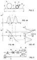
- FIG. 3 A birefringent fibre 21 having a total DIPS length L tuned to the frequency swing is locally wound in a single layer around a cylindrical tube 22 made of piezoelectric material.
- a voltage source 23 Connected between the outside and the inside surface of the tube is a voltage source 23 for supplying a periodically varying voltage to produce the piezoelectric effect.
- a polarisation variation according to the invention is, in addition, used in combination with a so-called line coding of the data signal to be transmitted, which line coding has an equal distribution of the 'zeros' and 'ones' per unit time, such as, for example, the Manchester code
- the power distribution of the IF signal is essentially symmetrical and it has clearly distinguishable peaks.
- This power distribution PD is shown as a function of the frequency F in FIG. 4(a).
- a frequency discriminator based on a discriminator curve C3 as shown in FIG. 4(b), which is of the same type as the curve C1 shown in FIG.
- FIG. 4(c) shows the mean of the output signal V C3 , which in fact forms the slow fluctuations thereof, as a function of the power distribution PD.
- This mean voltage value can therefore be used as an AFC control signal.
- the number of frequency discriminators required in the coherent receiver 3 of FIG. 1 can consequently be reduced to only one.
- Such a receiver is shown diagrammatically in FIG. 5.
- This coherent receiver comprises
Landscapes
- Physics & Mathematics (AREA)
- Electromagnetism (AREA)
- Engineering & Computer Science (AREA)
- Computer Networks & Wireless Communication (AREA)
- Signal Processing (AREA)
- Optical Communication System (AREA)
Applications Claiming Priority (2)
| Application Number | Priority Date | Filing Date | Title |
|---|---|---|---|
| NL9200748 | 1992-04-23 | ||
| NL9200748A NL9200748A (nl) | 1992-04-23 | 1992-04-23 | Optische signaaloverdracht met polarisatie-ongevoelige coherente detectie en frekwentiestabilisatie aan de ontvangstzijde. |
Publications (2)
| Publication Number | Publication Date |
|---|---|
| EP0567181A1 true EP0567181A1 (de) | 1993-10-27 |
| EP0567181B1 EP0567181B1 (de) | 1998-02-18 |
Family
ID=19860732
Family Applications (1)
| Application Number | Title | Priority Date | Filing Date |
|---|---|---|---|
| EP93201066A Expired - Lifetime EP0567181B1 (de) | 1992-04-23 | 1993-04-13 | Optische Signalübertragung mit polarisationsunempfindlicher kohärenter Detektion und Frequenzstabilisation auf der Empfangsseite |
Country Status (7)
| Country | Link |
|---|---|
| US (1) | US5424861A (de) |
| EP (1) | EP0567181B1 (de) |
| JP (1) | JPH0677906A (de) |
| AT (1) | ATE163333T1 (de) |
| DE (1) | DE69317007T2 (de) |
| ES (1) | ES2113469T3 (de) |
| NL (1) | NL9200748A (de) |
Families Citing this family (8)
| Publication number | Priority date | Publication date | Assignee | Title |
|---|---|---|---|---|
| FR2717331B1 (fr) * | 1994-02-18 | 1996-04-05 | Cit Alcatel | Système de communication optique à brouilleur de polarisation. |
| JP3303515B2 (ja) * | 1994-03-18 | 2002-07-22 | キヤノン株式会社 | 光通信方式及びそれを用いた光通信システム |
| JP3770635B2 (ja) * | 1995-06-20 | 2006-04-26 | 富士通株式会社 | 不要強度変調成分抑圧機能を有する光受信機 |
| JP3116348B2 (ja) * | 1998-02-24 | 2000-12-11 | 日本電気株式会社 | 光伝送システムの制御信号伝送方法とその装置 |
| US7447436B2 (en) * | 1999-12-29 | 2008-11-04 | Forster Energy Llc | Optical communications using multiplexed single sideband transmission and heterodyne detection |
| DE10243141B4 (de) * | 2002-09-17 | 2006-05-11 | Siemens Ag | Verfahren zur Übertragung von optischen Polarisationsmultiplexsignalen |
| JP5414354B2 (ja) * | 2009-05-15 | 2014-02-12 | 日本電信電話株式会社 | 光データ通信システム、ならびに通信装置および通信方法 |
| JP5549333B2 (ja) * | 2010-04-07 | 2014-07-16 | 富士通株式会社 | 偏波変動補償装置および光通信システム |
Citations (3)
| Publication number | Priority date | Publication date | Assignee | Title |
|---|---|---|---|---|
| EP0361150A2 (de) * | 1988-09-30 | 1990-04-04 | Siemens Aktiengesellschaft | Verfahren zum synchronisierten Umtasten eines Polarisationszustandes eines optischen Sendesignals eines optischen Übertragungssystems mit Überlagerungsempfang und Vorrichtung zur Durchführung des Verfahrens |
| US5008958A (en) * | 1988-01-19 | 1991-04-16 | At&T Bell Laboratories | Polarization-insensitive technique for coherent optical communication |
| EP0474914A1 (de) * | 1990-09-14 | 1992-03-18 | Siemens Aktiengesellschaft | Bidirektionales Telekommunikationssystem |
Family Cites Families (7)
| Publication number | Priority date | Publication date | Assignee | Title |
|---|---|---|---|---|
| US4783852A (en) * | 1985-09-18 | 1988-11-08 | Siemens Aktiengesellschaft | Method and apparatus for acquiring information using a relative phase deviation of the optical signal of a local oscillator of a homodyne receiver |
| NL8602380A (nl) * | 1986-09-22 | 1988-04-18 | Philips Nv | Inrichting voor optische heterodyne detektie van een optische signaalbundel en een optisch transmissiesysteem van een dergelijke inrichting voorzien. |
| GB8808043D0 (en) * | 1988-04-06 | 1988-05-25 | British Telecomm | Methods & apparatus for transmitting information |
| JPH07109994B2 (ja) * | 1988-07-29 | 1995-11-22 | 日本電気株式会社 | 偏波ダイバーシチ型光ヘテロダイン受信装置 |
| US5134509A (en) * | 1988-12-22 | 1992-07-28 | Gte Laboratories Incorporated | Coherent subcarrier multiplexed optical communication system |
| JPH0738615B2 (ja) * | 1989-08-21 | 1995-04-26 | 日本電信電話株式会社 | 光fsk周波数偏移安定化回路 |
| JPH0494230A (ja) * | 1990-08-09 | 1992-03-26 | Nec Corp | 光周波数偏移量安定化装置 |
-
1992
- 1992-04-23 NL NL9200748A patent/NL9200748A/nl unknown
-
1993
- 1993-04-13 DE DE69317007T patent/DE69317007T2/de not_active Expired - Fee Related
- 1993-04-13 EP EP93201066A patent/EP0567181B1/de not_active Expired - Lifetime
- 1993-04-13 ES ES93201066T patent/ES2113469T3/es not_active Expired - Lifetime
- 1993-04-13 AT AT93201066T patent/ATE163333T1/de not_active IP Right Cessation
- 1993-04-14 US US08/047,573 patent/US5424861A/en not_active Expired - Fee Related
- 1993-04-23 JP JP5131491A patent/JPH0677906A/ja active Pending
Patent Citations (3)
| Publication number | Priority date | Publication date | Assignee | Title |
|---|---|---|---|---|
| US5008958A (en) * | 1988-01-19 | 1991-04-16 | At&T Bell Laboratories | Polarization-insensitive technique for coherent optical communication |
| EP0361150A2 (de) * | 1988-09-30 | 1990-04-04 | Siemens Aktiengesellschaft | Verfahren zum synchronisierten Umtasten eines Polarisationszustandes eines optischen Sendesignals eines optischen Übertragungssystems mit Überlagerungsempfang und Vorrichtung zur Durchführung des Verfahrens |
| EP0474914A1 (de) * | 1990-09-14 | 1992-03-18 | Siemens Aktiengesellschaft | Bidirektionales Telekommunikationssystem |
Non-Patent Citations (4)
| Title |
|---|
| ECOC 90, 1990, pages 339 - 342 CHRISTENSEN ET. AL. 'Multivariable state feedback AFC for 2.5 gbit/s CPSFSK coherent optical communication system' * |
| ELECTRONICS LETTERS. vol. 23, no. 10, 7 May 1987, STEVENAGE GB pages 513 - 514 HODKINSON ET. AL. 'Polarisation insensitive heterodyne detection using polarisation scrambling' * |
| ELECTRONICS LETTERS. vol. 24, no. 22, 27 October 1988, STEVENAGE GB pages 1353 - 1354 WALKER AND WALKER 'Rugged all-fibre endless polarisation controller' * |
| ELECTRONICS LETTERS. vol. 25, no. 1, January 1989, STEVENAGE GB pages 4 - 5 NOE ET. AL. 'Polarisation-insensitive 500 m/bits FSK transmission over 153 km by passive polarisation switching' * |
Also Published As
| Publication number | Publication date |
|---|---|
| EP0567181B1 (de) | 1998-02-18 |
| US5424861A (en) | 1995-06-13 |
| ATE163333T1 (de) | 1998-03-15 |
| ES2113469T3 (es) | 1998-05-01 |
| JPH0677906A (ja) | 1994-03-18 |
| DE69317007T2 (de) | 1998-07-16 |
| NL9200748A (nl) | 1993-11-16 |
| DE69317007D1 (de) | 1998-03-26 |
Similar Documents
| Publication | Publication Date | Title |
|---|---|---|
| EP0337644B1 (de) | Verfahren und Gerät zur Nachrichtenübertragung | |
| US5390185A (en) | Transmission system for a combination of a main signal and an auxiliary signal | |
| EP0328156B1 (de) | Digitales Nachrichtenübertragungssystem und Verfahren | |
| US5162936A (en) | Apparatus for monitoring the operation of an optical repeater | |
| EP0404054B1 (de) | Verfahren und System zur Direktmodulations-Phasenumtastung | |
| US4965857A (en) | Method for synchronized polarization switching of an optical transmission signal of an optical transmission system having superheterodyne reception and an apparatus for the implementation of said method | |
| US5220448A (en) | Bit and frame synchronization unit for an access node of optical transmission equipment | |
| EP0329186A2 (de) | Optischer Polarisationsdiversitätsempfänger für kohärente optische Übertragung | |
| EP0564075A1 (de) | Optische Übertragung mit FSK-Modulation, Phasen-Kontinuität und geregeltem lokalem Oszillator | |
| EP0567181B1 (de) | Optische Signalübertragung mit polarisationsunempfindlicher kohärenter Detektion und Frequenzstabilisation auf der Empfangsseite | |
| US5323125A (en) | Frequency agile method for transmitting multi-level data | |
| US5023949A (en) | Apparatus for generating an FSK-modulated optical signal having two different polarization conditions for an optical transmission system having an optical two-filter FSK super-heterodyne receiver | |
| US4042884A (en) | Phase demodulator with offset frequency reference oscillator | |
| US20030002118A1 (en) | Methods and apparatus for locking the phase between clock and data in return-to-zero modulation format | |
| US5025487A (en) | System for transmitting information on interferometrically generated optical carriers | |
| JP2001251210A (ja) | リンク両端間における相互周波数ロック | |
| US5267074A (en) | Coherent optical heterodyne transmission system | |
| US5132829A (en) | Tone spacing and power level monitor for fsk lightwave systems | |
| EP0411566B1 (de) | Selbsttätiges optisches Gerät zur Frequenznachführung und Frequenzfolge für eine optische kohärente Kommunikationsanlage | |
| US5060311A (en) | Method and apparatus for obtaining phase or polarization insensitive optical heterodyne reception for dpsk or ask-modulated transmission signal | |
| EP0438832B1 (de) | Kohärentes optisches Überlagerungsübertragungssystem | |
| GB2237469A (en) | Optical transmission process and system | |
| US4686689A (en) | Phase-locked loop circuit | |
| US6178208B1 (en) | System for recovery of digital data from amplitude and phase modulated line signals using delay lines | |
| JP2633593B2 (ja) | コヒーレント光通信用偏波ダイバーシティ光受信装置 |
Legal Events
| Date | Code | Title | Description |
|---|---|---|---|
| PUAI | Public reference made under article 153(3) epc to a published international application that has entered the european phase |
Free format text: ORIGINAL CODE: 0009012 |
|
| AK | Designated contracting states |
Kind code of ref document: A1 Designated state(s): AT BE CH DE DK ES FR GB GR IE IT LI LU NL PT SE |
|
| 17P | Request for examination filed |
Effective date: 19940322 |
|
| 17Q | First examination report despatched |
Effective date: 19961217 |
|
| GRAG | Despatch of communication of intention to grant |
Free format text: ORIGINAL CODE: EPIDOS AGRA |
|
| GRAG | Despatch of communication of intention to grant |
Free format text: ORIGINAL CODE: EPIDOS AGRA |
|
| GRAH | Despatch of communication of intention to grant a patent |
Free format text: ORIGINAL CODE: EPIDOS IGRA |
|
| GRAH | Despatch of communication of intention to grant a patent |
Free format text: ORIGINAL CODE: EPIDOS IGRA |
|
| GRAA | (expected) grant |
Free format text: ORIGINAL CODE: 0009210 |
|
| AK | Designated contracting states |
Kind code of ref document: B1 Designated state(s): AT BE CH DE DK ES FR GB GR IE IT LI LU NL PT SE |
|
| PG25 | Lapsed in a contracting state [announced via postgrant information from national office to epo] |
Ref country code: GR Free format text: LAPSE BECAUSE OF FAILURE TO SUBMIT A TRANSLATION OF THE DESCRIPTION OR TO PAY THE FEE WITHIN THE PRESCRIBED TIME-LIMIT Effective date: 19980218 |
|
| REF | Corresponds to: |
Ref document number: 163333 Country of ref document: AT Date of ref document: 19980315 Kind code of ref document: T |
|
| REG | Reference to a national code |
Ref country code: CH Ref legal event code: NV Representative=s name: ISLER & PEDRAZZINI AG Ref country code: CH Ref legal event code: EP |
|
| PGFP | Annual fee paid to national office [announced via postgrant information from national office to epo] |
Ref country code: AT Payment date: 19980324 Year of fee payment: 6 |
|
| ITF | It: translation for a ep patent filed | ||
| PGFP | Annual fee paid to national office [announced via postgrant information from national office to epo] |
Ref country code: CH Payment date: 19980326 Year of fee payment: 6 Ref country code: BE Payment date: 19980326 Year of fee payment: 6 |
|
| REF | Corresponds to: |
Ref document number: 69317007 Country of ref document: DE Date of ref document: 19980326 |
|
| PGFP | Annual fee paid to national office [announced via postgrant information from national office to epo] |
Ref country code: LU Payment date: 19980331 Year of fee payment: 6 |
|
| PGFP | Annual fee paid to national office [announced via postgrant information from national office to epo] |
Ref country code: ES Payment date: 19980417 Year of fee payment: 6 |
|
| PG25 | Lapsed in a contracting state [announced via postgrant information from national office to epo] |
Ref country code: IE Free format text: LAPSE BECAUSE OF NON-PAYMENT OF DUE FEES Effective date: 19980418 |
|
| REG | Reference to a national code |
Ref country code: ES Ref legal event code: FG2A Ref document number: 2113469 Country of ref document: ES Kind code of ref document: T3 |
|
| ET | Fr: translation filed | ||
| PG25 | Lapsed in a contracting state [announced via postgrant information from national office to epo] |
Ref country code: PT Free format text: LAPSE BECAUSE OF FAILURE TO SUBMIT A TRANSLATION OF THE DESCRIPTION OR TO PAY THE FEE WITHIN THE PRESCRIBED TIME-LIMIT Effective date: 19980518 Ref country code: DK Free format text: LAPSE BECAUSE OF FAILURE TO SUBMIT A TRANSLATION OF THE DESCRIPTION OR TO PAY THE FEE WITHIN THE PRESCRIBED TIME-LIMIT Effective date: 19980518 |
|
| REG | Reference to a national code |
Ref country code: IE Ref legal event code: FG4D Free format text: 78923 |
|
| REG | Reference to a national code |
Ref country code: CH Ref legal event code: PFA Free format text: KONINKLIJKE PTT NEDERLAND N.V. TRANSFER- KONINKLIJKE KPN N.V. |
|
| RAP4 | Party data changed (patent owner data changed or rights of a patent transferred) |
Owner name: KONINKLIJKE KPN N.V. |
|
| PLBE | No opposition filed within time limit |
Free format text: ORIGINAL CODE: 0009261 |
|
| STAA | Information on the status of an ep patent application or granted ep patent |
Free format text: STATUS: NO OPPOSITION FILED WITHIN TIME LIMIT |
|
| NLR4 | Nl: receipt of corrected translation in the netherlands language at the initiative of the proprietor of the patent | ||
| 26N | No opposition filed | ||
| PG25 | Lapsed in a contracting state [announced via postgrant information from national office to epo] |
Ref country code: LU Free format text: LAPSE BECAUSE OF NON-PAYMENT OF DUE FEES Effective date: 19990413 Ref country code: AT Free format text: LAPSE BECAUSE OF NON-PAYMENT OF DUE FEES Effective date: 19990413 |
|
| PG25 | Lapsed in a contracting state [announced via postgrant information from national office to epo] |
Ref country code: ES Free format text: LAPSE BECAUSE OF NON-PAYMENT OF DUE FEES Effective date: 19990414 |
|
| PG25 | Lapsed in a contracting state [announced via postgrant information from national office to epo] |
Ref country code: LI Free format text: LAPSE BECAUSE OF NON-PAYMENT OF DUE FEES Effective date: 19990430 Ref country code: CH Free format text: LAPSE BECAUSE OF NON-PAYMENT OF DUE FEES Effective date: 19990430 Ref country code: BE Free format text: LAPSE BECAUSE OF NON-PAYMENT OF DUE FEES Effective date: 19990430 |
|
| BERE | Be: lapsed |
Owner name: KONINKLIJKE PTT NEDERLAND N.V. Effective date: 19990430 |
|
| REG | Reference to a national code |
Ref country code: CH Ref legal event code: PL |
|
| REG | Reference to a national code |
Ref country code: ES Ref legal event code: FD2A Effective date: 20010503 |
|
| REG | Reference to a national code |
Ref country code: GB Ref legal event code: IF02 |
|
| PGFP | Annual fee paid to national office [announced via postgrant information from national office to epo] |
Ref country code: NL Payment date: 20020328 Year of fee payment: 10 |
|
| PG25 | Lapsed in a contracting state [announced via postgrant information from national office to epo] |
Ref country code: NL Free format text: LAPSE BECAUSE OF NON-PAYMENT OF DUE FEES Effective date: 20031101 |
|
| NLV4 | Nl: lapsed or anulled due to non-payment of the annual fee |
Effective date: 20031101 |
|
| PG25 | Lapsed in a contracting state [announced via postgrant information from national office to epo] |
Ref country code: IT Free format text: LAPSE BECAUSE OF NON-PAYMENT OF DUE FEES;WARNING: LAPSES OF ITALIAN PATENTS WITH EFFECTIVE DATE BEFORE 2007 MAY HAVE OCCURRED AT ANY TIME BEFORE 2007. THE CORRECT EFFECTIVE DATE MAY BE DIFFERENT FROM THE ONE RECORDED. Effective date: 20050413 |
|
| PGFP | Annual fee paid to national office [announced via postgrant information from national office to epo] |
Ref country code: FR Payment date: 20060411 Year of fee payment: 14 |
|
| PGFP | Annual fee paid to national office [announced via postgrant information from national office to epo] |
Ref country code: SE Payment date: 20060413 Year of fee payment: 14 |
|
| PGFP | Annual fee paid to national office [announced via postgrant information from national office to epo] |
Ref country code: DE Payment date: 20060419 Year of fee payment: 14 |
|
| PGFP | Annual fee paid to national office [announced via postgrant information from national office to epo] |
Ref country code: GB Payment date: 20060420 Year of fee payment: 14 |
|
| GBPC | Gb: european patent ceased through non-payment of renewal fee |
Effective date: 20070413 |
|
| PG25 | Lapsed in a contracting state [announced via postgrant information from national office to epo] |
Ref country code: DE Free format text: LAPSE BECAUSE OF NON-PAYMENT OF DUE FEES Effective date: 20071101 |
|
| PG25 | Lapsed in a contracting state [announced via postgrant information from national office to epo] |
Ref country code: GB Free format text: LAPSE BECAUSE OF NON-PAYMENT OF DUE FEES Effective date: 20070413 |
|
| PG25 | Lapsed in a contracting state [announced via postgrant information from national office to epo] |
Ref country code: SE Free format text: LAPSE BECAUSE OF NON-PAYMENT OF DUE FEES Effective date: 20070414 |
|
| PG25 | Lapsed in a contracting state [announced via postgrant information from national office to epo] |
Ref country code: FR Free format text: LAPSE BECAUSE OF NON-PAYMENT OF DUE FEES Effective date: 20070430 |