EP0567267A2 - Diviseurs/combineurs à micro-ondes isolant les signaux - Google Patents
Diviseurs/combineurs à micro-ondes isolant les signaux Download PDFInfo
- Publication number
- EP0567267A2 EP0567267A2 EP93302902A EP93302902A EP0567267A2 EP 0567267 A2 EP0567267 A2 EP 0567267A2 EP 93302902 A EP93302902 A EP 93302902A EP 93302902 A EP93302902 A EP 93302902A EP 0567267 A2 EP0567267 A2 EP 0567267A2
- Authority
- EP
- European Patent Office
- Prior art keywords
- sections
- connector
- connectors
- coaxial
- hub
- Prior art date
- Legal status (The legal status is an assumption and is not a legal conclusion. Google has not performed a legal analysis and makes no representation as to the accuracy of the status listed.)
- Withdrawn
Links
Images

Classifications
-
- H—ELECTRICITY
- H01—ELECTRIC ELEMENTS
- H01P—WAVEGUIDES; RESONATORS, LINES, OR OTHER DEVICES OF THE WAVEGUIDE TYPE
- H01P5/00—Coupling devices of the waveguide type
- H01P5/12—Coupling devices having more than two ports
- H01P5/16—Conjugate devices, i.e. devices having at least one port decoupled from one other port
Definitions
- This invention relates generally to assemblages for handling microwave signals, and which may be splitters or combiners of such signals. More particularly, this invention relates to assemblages of such kind which comprise a primary signal transfer port, a plurality of secondary signal transfer ports, and a plurality of principal signal transfer paths each extending between a corresponding one of said secondary ports and said primary port.
- assemblages of such kind which comprise a primary signal transfer port, a plurality of secondary signal transfer ports, and a plurality of principal signal transfer paths each extending between a corresponding one of said secondary ports and said primary port.
- the assemblage is a combiner
- individual signals are received at the secondary ports and flow therefrom through such paths to the primary port to there combine to form an output signal from such port.
- an input signal to the primary port is distributed through such paths to such secondary ports to be split among them so as the convert the input signal into separate output signals.
- the signal which is an input to or an output from the primary port is a composite signal which consists of a combination of individual microwave signals in
- the assemblage described above is a combiner having six input ports receiving corresponding signals which are transferred from such ports to the common port to provide therefrom an output combining such originally separate signals.
- the signal which is received by the #1 input port and conducted in a path #1 from such port towards the output port a fraction of that signal will, on its reaching the end of the #1 path, be diverted through the output port to become a desired component of the composite output signal.
- the other five input ports are electrically coupled in parallel with the output port, otherfractions of the #1 signal will, unless something is done, reach such other input ports to there be manifested as extraneous signals.
- the presence of such extraneous signals at such ports in undesirable because they may flow reversely through such ports, and because of other detrimental electrical effects likely to be produced.
- a microwave circuit (which will be assumed to be a combiner circuit) comprises circuit boards and, also, transmission lines which are all in the form of striplines printed on such boards except that one of such lines is a coaxial line.
- a primary port is connected by a coaxial line Z 1 to a junction to which are also connected a plurality of striplines Z 2 connected at their ends away from such junction to corresponding secondary ports.
- the lines Z 2 provide principal paths for transfer of microwave signals between the secondary ports and the mentioned junction.
- any other secondary port In order for a signal received at any one secondary port to reach through principal paths any other secondary port as an extraneous signal, that signal must travel through two principal paths a distance between those two ports which is a half wavelength of the microwave signal at the midfrequency of the combiner. The results is that such extraneous signal undergoes a 180° phase shift in the course of such travel.
- these ports are respectively connected to a plurality of supplemental signal transfer paths each consisting of a stripline Z 3 and a stripline Z 4 in series, and all connected to a common floating point at their ends away from the secondary ports.
- supplemental signal transfer paths each consisting of a stripline Z 3 and a stripline Z 4 in series, and all connected to a common floating point at their ends away from the secondary ports.
- Each of such supplemental paths has a length of one half wavelength. Because of the existence of these supplemental paths, the signal received at any one secondary port can reach any other secondary port as an extraneous signal not only through two principal paths as described above but also through two supplemental paths.
- the circuit disclosed by the Gysel article has, however, the disadvantages that, because of the several odd impedance transmission lines required, stripline or microstrip construction is indicated.
- stripline does not work well, and the circuit is undesirably limited as to the microwave power it can handle as a result of the lower power carrying capacity of the striplines.
- a microwave assemblage comprising a primary coaxial signal-transfer connector, a plurality of first rigid equal-length coaxial line sections extending from inner ends thereof adjacent to and electrically coupled to said connector to outerends of such sections, means mechanically coupling said first sections at their inner ends in positionally fixed relation with each other and said connector, a plurality of secondary coaxial signal-transfer connectors respectively corresponding to said first sections and disposed at their outer ends in electrically coupled relation therewith, said secondary connectors being fixedly mechanically coupled with said rigid first sections to be positionally fixed relative to each other and said first sections, a plurality of second equal-length coaxial line sections respectively corresponding to said first sections and having respective outer and inner ends of which the outer ends are mechanically and electrically coupled with said first sections at their outer ends, and of which the inner ends of said second sections are adjacent to each other and electrically and mechanically coupled together, said second sections being of different lengths than said first sections, and
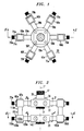
- the reference numeral 20 designates a microwave assemblage of which the structure is functionally suitable for use as either a six-way splitter or six-way combiner, but which will initially herein be considered to be a combiner.
- the combiner20 has a vertical axis 21, and upper and lower axially spaced hubs 22 and 23 coaxial with axis 21.
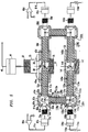
- Upper hub 22 is in the form of a moderately thick circular cylindrical disc having its centerplane normal to axis 21, and having therein a large circular cylindrical bore 30 (FIG. 5) extending axially all the way through the hub.
- Bore 30 at its lower end has an internally threaded wall with which is engaged peripheral threading on a closure disc 31 adapted by turning it to be removed from the bore to provide access to its interior.
- disc 31 is shown as only partly screwed into bore 30.
- connection 35 has a tubular outer conductor 37 externally threaded at its top, and the connector also has an inner filamental conductor 38 extending axially forward of conductor 37 to form a pin 39 projecting down into bore 30.
- the primary connector 35 is adapted to be electromechanically coupled to means which is external to the assemblage and which, for example, may be a coaxial cable 40 (FIG. 5) having at its end rear device 20 a fitting comprising a rotatable internally threaded cap 41 adapted to be threaded onto connector 35 to thereby couple the cable and connector together.
- Cable 40 may lead to, say, an antenna orotherdevice (not shown) which, when assemblage 20 is a combiner, receives and utilizes the composite microwave signal which is the output of the combiner 20.
- coaxial line sections have outer portions which are disposed outside hub 22, are of greater length than the inner hub portions, and project outward like spokes from the hub to form a star pattern in a common plane to which vertical axis 21 is normal.
- the first coaxial line sections 50 are all, mechanically speaking, rigid elements which are mechanically coupled together by hub 22 to all be in positionally fixed relation with each other and with the primary connector 35.
- first coaxial line section 50a consists of a single continuous length of a coaxial line comprising (FIG. 5) a filamental inner conductor 51a, a tubular outer conductor 52a and dielectric material 53a disposed between conductors 51a, 52a and maintaining them in concentric relation.
- the outer conductor 52a is an electroconductive pipe which renders rigid the coaxial line 50a, and which serves both as the grounded outer electrical conductor for that line and as its external protective sheath which, when outside hub 22, is exposed to the exterior environment of assemblage 20.
- junction 55 is surrounded by a copper grounding ring 56 electromechanically connected by solder to the outer conductors of all the coaxial lines 50a-50f at the inner ends ofthese conductors projecting into the bore 30.
- the box 60a comprises a cubic copper housing 61a, a cubic cavity 62a within that housing, registering circular passages 63a, 64a extending radially through housing 61a on radiallyoppo- site sides of cavity 62a, and registering circular passages 65a, 66a extending axially through housing 61a an axially opposite sides of that cavity.
- a radially outer portion of coaxial line 50a is received with a tight fit in the radially inner passage 63a in housing 61a, and the line and housing are soldered together. With the outer end of the line 50a being so received in that passage, the inner conductor 51a projects forwardly to the center region of cavity 62a.
- the box 60a is united to and supported by the rigid line 50a to be held thereby in fixed position relative to all of lines 50a-50f and the primary connector 35. All of the other boxes 60b-60f are similarly positionally fixed by their corresponding rigid lines 50b-50f to all other of such lines and connector 35.
- the six boxes 60a-60f carry six respectively corresponding secondary signal transfer coaxial connectors 70a-70f which are smaller in size than the primary connector 35, but which are of the same SMA type as is that connector.
- the connector 70a is exemplary of all of them.
- Connector 70a is mounted by screws 71a on the radially outer side of the housing 61 a of the box 60a to cover the outer end of, and be concentric with, the radial passage 64a (FIG. 5) through that housing.
- Connector 71a has an outer conductor 72a which is externally threaded at its radially outer end, and the connector also has an inner filamental conductor 73a projecting into the central region of cavity 62a of box 60a to there be united at an electromechanical solder junction 74a with the inner conductor 51a of the coaxial line 50a.
- the box 60a serves as a mechanical coupling of the connector 70a to the line 50a in fixed positional relation therewith so that such connector 70a is positionally fixed relative to all of elements 22, 35, 50a-50f and 60a-60f.
- the upper axial passage 65a through the housing 61 a of box 60a is shown as being closed at its out- erend by a thin sheet metal lid 67a.
- lid 67a Prior to and during the making of junction 74a by soldering, lid 67a is present on box 60a, and the passage 65a is open to provide access to the center of box cavity 62a to permit the making of that junction. After such junction has been formed, the lid 67a is soldered onto the top of box housing 61a.
- the secondary connectors 70a-70f receive respective inputs from six microwave signal sources which may be, say microwave amplifiers of which the amplifiers 80a and 80d (FIG. 5) are exemplary.
- the output of amplifier 80a is connected to one end of a coaxial cable 81a terminating at its other end in a fitting comprising an internally threaded rotatable cap 82a.
- the cap 82a is turned to engage its threading with the external threading on connector 70a so as to couple amplifier 80a through cable 81 a to connector 70a.
- the other microwave amplifiers which respectively correspond to connectors 70b-70f are, in the use of combiner 20, similarly coupled to their corresponding connectors.
- the coaxial lines 50a-50f serve as principal paths for transfer of such signals from such secondary connectors to the primary connector 35.
- a fraction of the microwave signal which is an input to any one of the secondary connectors will appear as an extraneous signal of significant level at all other of such secondary connectors in the absence of means to prevent that occurrence.
- Microwave assemblage 20 has such means which is as follows.
- Assemblage 20 includes not only six “first” coaxial line sections 50a-50f but also six “second” coaxial line sections 100a-100f which respectively correspond to those first sections, and of which the second section 100a is exemplary.
- Section 100a is a composite structure having the shape of an "L” and comprising a radially outer vertical coaxial line 110a corresponding to the vertical arm of the "L", a radially extending horizontal coaxial line 120a corresponding to the horizontal arm of the "L” and a junction box 130a in the form of a hollow cube and disposed at the bend of the "L" where its arms intersect.
- the "L” shaped sections 100 define and lie in respective planes which are all substantially at a right angle to the common plane of the first coaxial line sections 50.
- the junction box 130a comprises a copper housing 131a, a cubic cavity 132a inclosed by that housing, registering radial passages 133a and 134a passing through inner and outer sides of housing 131a a on radially opposite sides of cavity 132a, and registering axial passages 135a, 136a passing through upper and lower sides of housing 131a on axially opposite sides of the mentioned cavity.
- Upper axial passage 135a has received therein with a tight fit the lower end of vertical coaxial line 110a of which the upper end is received with a tight fit within the lower axial passage 66a formed in junction box 60a.
- Line 110a is also soldered to both of junction boxes 60a and 130a.
- line 110a is a rigid coaxial line similar in construction to the line 50a earlier described.
- line 110a being a rigid line and its tight fit within boxes 60a and 130a and its solder connection to both such boxes, the line 110a maintains box 130a in fixed positional relation to box 60a and, also, because of the fixed positional relations already described, to elements 50a-50f, 60a-60f, 70a-70f, hub 22 and primary connector 35.
- the vertical coaxial line 110a comprises an outer conductor 111a in the form of a rigid electroconductive pipe, a filamental inner conductor 112a and dielectric material 113a disposed between conductors 111a and 112a and maintaining them in positionally fixed concentric relation.
- the upper end of inner conductor 112a projects into cavity 62a of box 60a to be united with the electromechanical junction 74a in that cavity of the inner conductors of, respectively, the secondary connector 70a and the "first" coaxial line 50a.
- the lower end of conductor 112 a projects into the central region of the cavity 132a of the junction box 130a.
- the junction boxes 130 are at the level of the lower hub 23 of the assemblage 20.
- Hub 23 is disposed with its center plane normal to the assemblage axis 21, and the hub is similar in external shape to hub 22.
- Hub 23 has formed therein a large central cylindrical bore 140 (FIG. 5) having an opening at the bottom of the hub and extending upwards from that opening.
- Bore 140 does not, however, pass all the way vertically through the hub but, rather, is closed at its top by a web 141 so as to be a blind passage through the bore.
- the wall of bore 140 at its bottom has internal threading engaging with peripheral threading on a closure disc 142 adapted by its turning to selectively either be removed from the bore or to be inserted therein so as to form a closure for its bottom. In FIG. 2 and 15 the disc 142 is shown as partly removed from bore 140.
- the line 120a has its radially inner end and radially outer end received with a tight fit in, respectively, the radial passage 133a through the radially inner side of junction box housing 131a, and the radial passage 145a in the hub 23. Further, the line 120a is a rigid line soldered both to junction box 130a and hub 23. Because of the tight fit of line 120a in the two passages just mentioned and the rigidity of such line and its soldering to elements 23 and 130a, and, because, moreover, of the fixed positional relations already described as having been established, the coaxial line 120a helps support hub 23, and is itself supported, to be in positionally fixed relation to all the other elements included in assemblage 20.
- the coaxial line 120a is similar to the coaxial line 110a already described. That is, the line 120a comprises an outer conductor 121a in the form of a rigid electroconductive pipe, an inner filamental conductor 122a and dielectric material 123a disposed between conductors 121a and 122a to maintain them concentric.
- the radially outer end of conductor 122a extends into the central region of the cavity 132a of junction box 130a so that the tip of conductor 122a is united to the tip of inner conductor 112a at an electromechanical junction 137a of those two inner conductors.
- junction 137a by soldering, the lower axial passage 136a of box 130a is kept open to provide access to the interior of such junction but thereafter that passage is closed by a lid 138a soldered to box 130a.
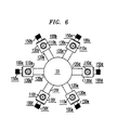
- junction 146 The radially inner end of inner conductor 122a projects into the central region of the bore 140 in hub 23 to an electromechanical junction disposed in that region and designated as junction 146 and constituting an electromechanical junction of the radially inner ends of all of the inner conductors 120 of the second coaxial line sections 100a-100f.
- each of such other "L" shaped sections 100b-100f is, at its upper end (a) fixedly coupled mechanically to the corresponding one of junction boxes 60b-60f, and (b) electrically coupled by the inner conductor of its axially aligned coaxial line to the junction of the respective inner conductor of the corresponding one of first coaxial line sections 50b-50f and the corresponding one of secondary connectors 70b-70f, and, each of sections 100b-100f is, at its radially inner end, (c) fixedly mechanically coupled to hub 23, and (d) electrically coupled by the inner conductor of its radial coaxial line to junction 146 which, as stated, is the common junction of the radially inner ends of the inner conductors of all of the coaxial line sections 100a-100f.
- the junction 146 serves, electrically speaking, as a common floating point for such inner conductors.
- the junction is surrounded in bore 140 by a copper grounding ring 147 (FIG. 4) electromechanically connected by solder to the outer conductors of radial coaxial lines 120a-120f at the inner ends of those conductors projecting radially into the bore.
- Each of those lines 120 lies in the same axial-radial plane as does the corresponding one of the coaxial lines 50, and, as in the case of those upper radial lines 50 the lower radially extending lines 120 have outer portions projecting out in a star pattern from the periphery of hub 23.
- junction boxes 130a-130f at the bends of the L-shaped second coaxial line sections 100a-100f serve as supports for a set of respectively corresponding external load coaxial connectors 150a-15f (FIG. 6) of which the connectors 150a and 150d (FIGS. 2 and 5) are exemplary.
- the connector 150a is mounted by screws 151a on the radially outer side of junction box 130a, is a standard type coaxial connector, and comprises an outer conductor 152a which is externally threaded at its radially outer end, and, also, an inner conductor 153a extending onto the cavity 132a of junction box 130a to be united at junction 137a with the inner conductors of the coaxial lines 110a and 120a.
- FIG. 5 shows in association with connector 150a a grounded external load resistor 154a attached at its non-grounded end to a coaxial cable 155a terminating at its end away from the resistor in a fitting comprising an internally threaded rotatable cap 156a.
- the cap 156a is threaded into the outer conductor 152a of connector 150a to electrically couple resistor 154a through cable 155a to coaxial section 100a at the junction of the two coaxial lines 110a and 120a included in that section.
- the whole assemblage 20 is a rigid mechanical structure which is rugged and durable, and which completely confines within its interior the microwave signals transferred thereby.
- the assemblage is efficient in design in that it requires no boards or the like to provide support and that, with the exception of hubs 22 and 23, all of the elements of the assemblage have both a mechanical function and an electrical function.
- Asignificantfactor in imparting rigidity to the structure as a whole of assemblage 20 is the rigid character of its various coaxial lines which serve as struts in coupling the hubs and the junction boxes to each other, and which are the only elements providing such couplings. That is, it is clear that if such coaxial lines were non-rigid, the hub 23, for example would not be maintained positionally fixed relative to hub 22.
- the outer conductors of all of its coaxial connectors and coaxial lines are electrically grounded.
- the midfrequency for the microwave signal transferred through primary connector 35 from or to the assemblage may conveniently be 1.847GHz.
- All of the first coaxial line sections 50a-50f have the same electrical length, and all of the second coaxial line sections 100a-100f have the same electrical length.
- the first fraction of a microwave signal at any one of such secondary connectors which is transmitted through ones of such principal paths to any other of such connectors as an extraneous signal is, as earlier described, opposed at such other connector by a second fraction of such signal traveling from such one to the other connector through one of supplemental paths provided by coaxial line sections 100a-100f, and appearing at such other connector as a second fraction of an extraneous signal in 180° phase relation to the mentioned first fraction.
- the coaxial lines llOa-110fand 120a-120f each have a characteristic impedance of 50 ohms
- the coaxial lines 50a-50f each have a characteristic impedance of 122 ohms
- the primary connector 35 has a characteristic impedance of 50 ohms
- the secondary coaxial connectors 70a-70f have a characteristic impedance of 50 ohms
- the external load resistors 154 have a resistance of 50 ohms.
- assemblage 20 has been described in terms of its use as a combiner, it is equally capable of being used as a microwave signal splitter by making minor changes in the relationship of assemblage 20 to the external instrumentalities with which it is connected.
- the changes necessary to convert assemblage 20 into a splitter one are that the external means 40 connected to primary connector 35 becomes a source of microwave signals supplied as an input to such connectors, and that the connector 70 supply microwave signals to the inputs of amplifiers 80.
- N is the number of secondary coaxial connectors
- the number N for the particular splitter/combiner described above is six since six such connectors 70a-70f have been disclosed.
- assemblage 20 can be constructed so that the N is the number 2 at a minimum or any integral number which is greater than 2 but small enough to permit incorporation of secondary connectors of that number within the structure of the assemblage.
- a preferred modified construction of hubs 22 and 23 is as follows.
- Each hub is split along its equatorial centerplane to convert the hub into two halves and to convert the small radial bores of the hub into registering pairs of grooves which are almost hemicylindrical but not quite in that their cylindrical surfaces angularly extend by a small amount less than 180° about the axes of such grooves.
- the respective planes defined by the coaxial line sections 100 may be shifted relative to the common plane of coaxial line sections by tilting those respective planes relative to such common plane in one angular direction (clockwise or counterclockwise) around axis 21 so that such respective planes are "folded down" towards that common plane to each make only a small acute angle therewith, so as, thereby, to provide for the assemblage a configuration which is more compact in the vertical direction, and which, in the extreme case (and where there are no more than four sections 50 and 100) may resemble a pancake.
Landscapes
- Coupling Device And Connection With Printed Circuit (AREA)
Applications Claiming Priority (2)
| Application Number | Priority Date | Filing Date | Title |
|---|---|---|---|
| US873306 | 1992-04-24 | ||
| US07/873,306 US5223809A (en) | 1992-04-24 | 1992-04-24 | Signal isolating microwave splitters/combiners |
Publications (2)
| Publication Number | Publication Date |
|---|---|
| EP0567267A2 true EP0567267A2 (fr) | 1993-10-27 |
| EP0567267A3 EP0567267A3 (fr) | 1994-11-02 |
Family
ID=25361370
Family Applications (1)
| Application Number | Title | Priority Date | Filing Date |
|---|---|---|---|
| EP9393302902A Withdrawn EP0567267A3 (fr) | 1992-04-24 | 1993-04-15 | Diviseurs/combineurs à micro-ondes isolant les signaux. |
Country Status (3)
| Country | Link |
|---|---|
| US (1) | US5223809A (fr) |
| EP (1) | EP0567267A3 (fr) |
| JP (1) | JP3470817B2 (fr) |
Cited By (1)
| Publication number | Priority date | Publication date | Assignee | Title |
|---|---|---|---|---|
| DE19628949B4 (de) * | 1995-02-02 | 2008-12-04 | Muegge Electronic Gmbh | Vorrichtung zur Erzeugung von Plasma |
Families Citing this family (17)
| Publication number | Priority date | Publication date | Assignee | Title |
|---|---|---|---|---|
| US5351019A (en) * | 1992-12-15 | 1994-09-27 | Alcatel Network Systems, Inc. | Local area network interface and interfacing method for network element |
| CA2105043C (fr) * | 1993-08-27 | 1999-10-12 | Osvaldo Monti | Composants et systemes electroniques utilisant la technologie des cables coaxiaux |
| US5376902A (en) * | 1993-08-31 | 1994-12-27 | Motorola, Inc. | Interconnection structure for crosstalk reduction to improve off-chip selectivity |
| US5613234A (en) * | 1994-10-28 | 1997-03-18 | Lucent Technologies Inc. | Receive filter using frequency translation for or in cellular telephony base station |
| US5916259A (en) * | 1995-09-20 | 1999-06-29 | Sun Microsystems, Inc. | Coaxial waveguide applicator for an electromagnetic wave-activated sorption system |
| US5842356A (en) * | 1995-09-20 | 1998-12-01 | Sun Microsystems, Inc. | Electromagnetic wave-activated sorption refrigeration system |
| ATE220192T1 (de) * | 1995-09-20 | 2002-07-15 | Sun Microsystems Inc | Sorptionspaar verwendende kälteanlage |
| US5873258A (en) * | 1995-09-20 | 1999-02-23 | Sun Microsystems, Inc | Sorption refrigeration appliance |
| US6244056B1 (en) | 1995-09-20 | 2001-06-12 | Sun Microsystems, Inc. | Controlled production of ammonia and other gases |
| US5855119A (en) * | 1995-09-20 | 1999-01-05 | Sun Microsystems, Inc. | Method and apparatus for cooling electrical components |
| US5880648A (en) * | 1997-04-21 | 1999-03-09 | Myat, Inc. | N-way RF power combiner/divider |
| US7003979B1 (en) | 2000-03-13 | 2006-02-28 | Sun Microsystems, Inc. | Method and apparatus for making a sorber |
| US6919776B1 (en) * | 2002-04-23 | 2005-07-19 | Calabazas Creek Research, Inc. | Traveling wave device for combining or splitting symmetric and asymmetric waves |
| US7603570B2 (en) * | 2004-05-13 | 2009-10-13 | Cisco Technology, Inc. | Power delivery over ethernet cables |
| DE102013213297B4 (de) | 2013-07-01 | 2019-12-05 | Rohde & Schwarz Gmbh & Co. Kg | Mikrowellenanordnung zur Übertragung von Hochfrequenzsignalen |
| JP6566465B2 (ja) * | 2015-03-26 | 2019-08-28 | 国立大学法人広島大学 | 異常組織検出装置及び信号送受信方法 |
| US10193512B1 (en) | 2018-01-05 | 2019-01-29 | Werlatone, Inc. | Phase-shifting power divider/combiner assemblies and systems |
Family Cites Families (14)
| Publication number | Priority date | Publication date | Assignee | Title |
|---|---|---|---|---|
| US3529265A (en) * | 1969-09-29 | 1970-09-15 | Adams Russel Co Inc | Radio frequency power divider |
| US4032849A (en) * | 1976-09-01 | 1977-06-28 | The United States Of America As Represented By The Secretary Of The Navy | Planar balanced mixer/converter for broadband applications |
| US4175257A (en) * | 1977-10-05 | 1979-11-20 | United Technologies Corporation | Modular microwave power combiner |
| US4163955A (en) | 1978-01-16 | 1979-08-07 | International Telephone And Telegraph Corporation | Cylindrical mode power divider/combiner with isolation |
| US4323863A (en) * | 1978-01-16 | 1982-04-06 | Rockwell International Corporation | N-Way power divider/combiner |
| US4234854A (en) * | 1978-05-12 | 1980-11-18 | Westinghouse Electric Corp. | Amplifier with radial line divider/combiner |
| US4263568A (en) * | 1979-03-12 | 1981-04-21 | International Telephone And Telegraph Corporation | Large scale low-loss combiner and divider |
| US4394629A (en) * | 1981-03-31 | 1983-07-19 | Rca Corporation | Hybrid power divider/combiner circuit |
| US4375622A (en) * | 1981-04-20 | 1983-03-01 | Motorola, Inc. | Multiport radio frequency signal combiner |
| GB2157504B (en) * | 1984-03-21 | 1987-05-28 | Plessey Co Plc | Radially fed microwave signal combiner/distributor apparatus |
| DE3684709D1 (de) * | 1985-10-03 | 1992-05-07 | Hughes Aircraft Co | In einem radialwellenleiter ausgefuehrter reaktanzfreier leistungsverteiler/-addierer mit integriertem modefilter. |
| WO1987002187A1 (fr) * | 1985-10-03 | 1987-04-09 | Hughes Aircraft Company | Repartiteur/combinateur de puissance a lignes radiales de forte isolation et a large bande |
| GB2232028B (en) | 1989-05-05 | 1992-12-09 | Marconi Co Ltd | Radio frequency network |
| US4931747A (en) * | 1989-05-30 | 1990-06-05 | Microwave Components And Systems, Inc. | Microwave power amplifier |
-
1992
- 1992-04-24 US US07/873,306 patent/US5223809A/en not_active Expired - Lifetime
-
1993
- 1993-04-15 EP EP9393302902A patent/EP0567267A3/fr not_active Withdrawn
- 1993-04-23 JP JP09633593A patent/JP3470817B2/ja not_active Expired - Fee Related
Cited By (1)
| Publication number | Priority date | Publication date | Assignee | Title |
|---|---|---|---|---|
| DE19628949B4 (de) * | 1995-02-02 | 2008-12-04 | Muegge Electronic Gmbh | Vorrichtung zur Erzeugung von Plasma |
Also Published As
| Publication number | Publication date |
|---|---|
| EP0567267A3 (fr) | 1994-11-02 |
| JPH0685516A (ja) | 1994-03-25 |
| US5223809A (en) | 1993-06-29 |
| JP3470817B2 (ja) | 2003-11-25 |
Similar Documents
| Publication | Publication Date | Title |
|---|---|---|
| US5223809A (en) | Signal isolating microwave splitters/combiners | |
| US5283540A (en) | Compact signal isolating microwave splitters/combiners | |
| US5264860A (en) | Metal flared radiator with separate isolated transmit and receive ports | |
| CA2145446C (fr) | Alimentation d'antenne et reseau de mise en forme de faisceau | |
| US4163955A (en) | Cylindrical mode power divider/combiner with isolation | |
| CA1145843A (fr) | Antenne coaxiale a radiateurs dephases | |
| US5936594A (en) | Highly isolated multiple frequency band antenna | |
| AU658091B2 (en) | Monopulse array system with air-stripline multi-port network | |
| US5410281A (en) | Microwave high power combiner/divider | |
| US4583061A (en) | Radio frequency power divider/combiner networks | |
| US5373299A (en) | Low-profile wideband mode forming network | |
| US5600286A (en) | End-on transmission line-to-waveguide transition | |
| US4035807A (en) | Integrated microwave phase shifter and radiator module | |
| US5206611A (en) | N-way microwave power divider | |
| US4612548A (en) | Multi-port radio frequency networks for an antenna array | |
| US4988963A (en) | High frequency coaxial line coupling device | |
| US5717405A (en) | Four-port phase and amplitude equalizer for feed enhancement of wideband antenna arrays with low sum and difference sidelobes | |
| US4039975A (en) | E plane folded hybrid with coaxial difference port | |
| US5982338A (en) | Rectangular coaxial line to microstrip line matching transition and antenna subarray including the same | |
| GB2219438A (en) | Coupling transmission lines | |
| US5883552A (en) | Microwave power divider/combiner structures | |
| US3587004A (en) | Contradirectional couplers | |
| EP0297865A2 (fr) | Connecteur de ligne pour transmission de données | |
| US5347243A (en) | Non-contacting waveguide "T" switch | |
| US4396921A (en) | Matching section for multi-arm spiral antenna |
Legal Events
| Date | Code | Title | Description |
|---|---|---|---|
| PUAI | Public reference made under article 153(3) epc to a published international application that has entered the european phase |
Free format text: ORIGINAL CODE: 0009012 |
|
| AK | Designated contracting states |
Kind code of ref document: A2 Designated state(s): DE ES FR GB IT NL SE |
|
| RAP3 | Party data changed (applicant data changed or rights of an application transferred) |
Owner name: AT&T CORP. |
|
| PUAL | Search report despatched |
Free format text: ORIGINAL CODE: 0009013 |
|
| AK | Designated contracting states |
Kind code of ref document: A3 Designated state(s): DE ES FR GB IT NL SE |
|
| 17P | Request for examination filed |
Effective date: 19950421 |
|
| 17Q | First examination report despatched |
Effective date: 19970623 |
|
| GRAG | Despatch of communication of intention to grant |
Free format text: ORIGINAL CODE: EPIDOS AGRA |
|
| GRAG | Despatch of communication of intention to grant |
Free format text: ORIGINAL CODE: EPIDOS AGRA |
|
| STAA | Information on the status of an ep patent application or granted ep patent |
Free format text: STATUS: THE APPLICATION IS DEEMED TO BE WITHDRAWN |
|
| 18D | Application deemed to be withdrawn |
Effective date: 19990824 |