EP0567361B2 - Système de fixation de panneaux modulaires de criblage sur une structure de maintien - Google Patents
Système de fixation de panneaux modulaires de criblage sur une structure de maintien Download PDFInfo
- Publication number
- EP0567361B2 EP0567361B2 EP93400760A EP93400760A EP0567361B2 EP 0567361 B2 EP0567361 B2 EP 0567361B2 EP 93400760 A EP93400760 A EP 93400760A EP 93400760 A EP93400760 A EP 93400760A EP 0567361 B2 EP0567361 B2 EP 0567361B2
- Authority
- EP
- European Patent Office
- Prior art keywords
- panels
- edges
- forming
- spacer
- supporting structure
- Prior art date
- Legal status (The legal status is an assumption and is not a legal conclusion. Google has not performed a legal analysis and makes no representation as to the accuracy of the status listed.)
- Expired - Lifetime
Links
- 238000012216 screening Methods 0.000 claims abstract description 31
- 125000006850 spacer group Chemical group 0.000 claims abstract description 26
- 238000004873 anchoring Methods 0.000 claims 2
- 230000000149 penetrating effect Effects 0.000 claims 2
- 230000000903 blocking effect Effects 0.000 abstract description 3
- 239000004744 fabric Substances 0.000 description 8
- 239000000463 material Substances 0.000 description 7
- XLYOFNOQVPJJNP-UHFFFAOYSA-N water Substances O XLYOFNOQVPJJNP-UHFFFAOYSA-N 0.000 description 5
- 230000015572 biosynthetic process Effects 0.000 description 3
- 230000000694 effects Effects 0.000 description 3
- 238000000034 method Methods 0.000 description 3
- 229920002635 polyurethane Polymers 0.000 description 3
- 239000004814 polyurethane Substances 0.000 description 3
- 229910000831 Steel Inorganic materials 0.000 description 2
- 208000018747 cerebellar ataxia with neuropathy and bilateral vestibular areflexia syndrome Diseases 0.000 description 2
- 238000009434 installation Methods 0.000 description 2
- 239000010959 steel Substances 0.000 description 2
- 238000005299 abrasion Methods 0.000 description 1
- 230000000712 assembly Effects 0.000 description 1
- 238000000429 assembly Methods 0.000 description 1
- 238000005452 bending Methods 0.000 description 1
- 230000002301 combined effect Effects 0.000 description 1
- 238000010276 construction Methods 0.000 description 1
- 230000008878 coupling Effects 0.000 description 1
- 238000010168 coupling process Methods 0.000 description 1
- 238000005859 coupling reaction Methods 0.000 description 1
- 230000005489 elastic deformation Effects 0.000 description 1
- 238000003780 insertion Methods 0.000 description 1
- 230000037431 insertion Effects 0.000 description 1
- 239000007788 liquid Substances 0.000 description 1
- 230000004048 modification Effects 0.000 description 1
- 238000012986 modification Methods 0.000 description 1
- 238000007789 sealing Methods 0.000 description 1
- 238000000926 separation method Methods 0.000 description 1
- 230000035939 shock Effects 0.000 description 1
- 238000007873 sieving Methods 0.000 description 1
- 238000005406 washing Methods 0.000 description 1
Images

Classifications
-
- B—PERFORMING OPERATIONS; TRANSPORTING
- B07—SEPARATING SOLIDS FROM SOLIDS; SORTING
- B07B—SEPARATING SOLIDS FROM SOLIDS BY SIEVING, SCREENING, SIFTING OR BY USING GAS CURRENTS; SEPARATING BY OTHER DRY METHODS APPLICABLE TO BULK MATERIAL, e.g. LOOSE ARTICLES FIT TO BE HANDLED LIKE BULK MATERIAL
- B07B1/00—Sieving, screening, sifting, or sorting solid materials using networks, gratings, grids, or the like
- B07B1/46—Constructional details of screens in general; Cleaning or heating of screens
- B07B1/4609—Constructional details of screens in general; Cleaning or heating of screens constructional details of screening surfaces or meshes
- B07B1/4645—Screening surfaces built up of modular elements
-
- F—MECHANICAL ENGINEERING; LIGHTING; HEATING; WEAPONS; BLASTING
- F16—ENGINEERING ELEMENTS AND UNITS; GENERAL MEASURES FOR PRODUCING AND MAINTAINING EFFECTIVE FUNCTIONING OF MACHINES OR INSTALLATIONS; THERMAL INSULATION IN GENERAL
- F16B—DEVICES FOR FASTENING OR SECURING CONSTRUCTIONAL ELEMENTS OR MACHINE PARTS TOGETHER, e.g. NAILS, BOLTS, CIRCLIPS, CLAMPS, CLIPS OR WEDGES; JOINTS OR JOINTING
- F16B19/00—Bolts without screw-thread; Pins, including deformable elements; Rivets
- F16B19/04—Rivets; Spigots or the like fastened by riveting
- F16B19/08—Hollow rivets; Multi-part rivets
- F16B19/10—Hollow rivets; Multi-part rivets fastened by expanding mechanically
- F16B19/1027—Multi-part rivets
- F16B19/1036—Blind rivets
- F16B19/1081—Blind rivets fastened by a drive-pin
Definitions
- the present invention relates to a system for fixing of modular screening panels to a support structure.
- the screening fabrics were originally made essentially from preformed steel wire then woven. We are moving more and more towards screening panels made from polyurethane due to its abrasion resistance. These new materials have been developed following two major categories: on the one hand, we find the so-called stretched fabrics or straps that are immediately adaptable instead of traditional steel canvases; on the other hand, there are also so-called modular fabrics which consist of panels to fix the next to each other. The latter solution requires a significant change in the support structure of the screen, this modification also being specific to each modular system.
- a screening installation essentially consists by a vibrating frame on which is fixed a support structure made up of profiles which are fixed parallel to each other with a fixed center distance and modular screening panels which are fixed themselves by their edges on these profiles.
- a support structure made up of profiles which are fixed parallel to each other with a fixed center distance and modular screening panels which are fixed themselves by their edges on these profiles.
- Document EP-A-0 167 999 describes one of these solutions.
- FIG. 1 attached shows the method of attachment described in the document mentioned above.
- a part of the profile 10 is shown on which the modular screening panels 12 and 14 must be fixed.
- the upper face 16 of the profile 10 is provided with a longitudinal slot 18.
- the fixing of the panels 12 and 14 on the profile is made using a strip 20.
- Recesses 22, 24 are provided in the edges opposite the screening panels 12 and 14.
- the fixing strip 20 has a flared head 26 which enters the recesses 22 and 24, a foot 28 forming a clip engaged in the slot 18 of the profile 10 and a intermediate part forming lips 30 interposed between the upper face 16 of the profile 10 and the lower face the edges of the screening panels 12 and 14.
- an object of the present invention is to provide a fastening system modular screening panels on a structure on the one hand, which allows mounting and easy dismantling of the panels and, on the other hand, avoids the formation of the gutters mentioned above.
- the invention effectively also avoids the formation of gutters as it appeared with the techniques of the prior art. Indeed, hats cover the edges of the screening panels the along their joining edge. Consequently, we does not obtain the formation of a gutter but at on the contrary, an oversized part which tends to channel wash water and materials to be screened to active screening areas, i.e. areas with of perforations.
- FIGS. 2 to 4 are simply intended to illustrate the characteristics of a panel fastening system screening. Only Figures 5 and 6 illustrate the embodiment of the invention.
- This figure shows the panels modular 40 and 42 which must be fixed together by their facing edge 40a and 42a and fixed on the structure of which a section 44 is shown.
- This section is provided on its upper face 46 with a longitudinal slot 48 arranged in the direction of the edges assembly of panels 40 and 42.
- the system of fixing consists of two locking elements 50 and 52 preferably made up of locking pins, and by a spacer piece 54.
- the edges 40a and 42a panels 40 and 42 are provided, in their part according to their thickness, a groove 55 and 56 which may preferably be in the form of a dovetail.
- the face 58 of the edge 40a disposed below the groove 55 is set back from the edge 60 of the part of the edge of the panel arranged above of groove 55.
- Each locking pin 50, 52 comprises a body 61 whose thickness is substantially equal to the difference in position between the faces 58 and 60, a heel 62 disposed at the upper part of the body 61 to enter the groove 55 or 56, and to its lower end a portion in excess thickness 68 which is defined by an inclined surface 70 facing the other panel.
- the body 61 of each locking pin has at the level of heel 62 a triangular cross section groove 72.
- the locking pins 50 and 52 in a first time, are respectively engaged in the grooves 55 and 56.
- the length of the body of each post is sufficient so that after positioning the panels 40 and 42, the portions 68 in excess of these pins are arranged inside the profiles 44, that is to say beyond their upper wall 46.
- the spacer piece 54 also includes a body 74 of shape with a substantially rectangular cross section and elongated in the direction of the edges of the panels which can be reinforced with a metallic core 76. This body may have a triangular cross-section projection 78 to cooperate with your throat 72 studs blocking.
- the room spacer 54 has a cap 80 whose width in the plane of the panels 40 and 42 is very substantially greater than that of the body 78.
- the hat On the periphery on its underside, the hat may have a lip 82, 84 on either side of body 74.
- Figure 4 shows how to fix the panels 40 and 42 on the profile 44 using the first embodiment of the invention.
- Locking pins 50 and 52 having already been placed in edges 40a and 42a panels, the body of the spacer piece 54 is engaged between the internal faces of the tenons 50 and 52.
- the body of the spacer exerts pressure on the tenons causing a certain deformation of these.
- the spacer piece 54 reaches the end of its travel, its end 88 causes the separation of the ends in excess thickness 68 of the locking pins. So, the assembly constituted by the locking pins and the spacer piece is riveted in the slot 48 of the profit by spacing of the portions 68 of the studs anchor.
- the throat 72 locking pins and corresponding projections 78 of the spacer piece ensures immobilization of the latter in the locking pins according to the vertical direction.
- the lips 84 and 82 arranged on either side of the body of the spacer piece form of sealing lips in contact with the upper face of the edges 42a and 40a of the panels screening to be fixed.
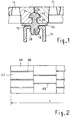
- FIG 2 there is shown in top view a preferred arrangement of the screening panels 40, 42. Instead of these being aligned, they are arranged in a staggered arrangement. So the 80 hats of the different fastening assemblies constitute baffles which thus impose on the materials to be screened and the liquid wash to actually go into the areas of the panels modular with screening holes. Of course, the profiles forming the supporting structure have the same staggered arrangement.
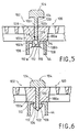
- FIG 5 two panels are shown adjacent 100 and 102 which must be joined between them and fixed on the section 44 provided with its longitudinal slot 48.
- the edges 100a and 102a of the panels are extended beyond their bearing face 100b and 102b on the profile 44 by longitudinal extensions 106 and 108.
- Each extension has a first portion 110 which extends the face 100c, 102c from the edges 100 and 102 and by a second portion 112 extending perpendicularly to portion 110.
- Functionally the portions 112 are equivalent to the extra thicknesses 68 of Figure 3.
- Extensions 106 and 108 are defined in such a way that they can enter the slot 48 of the profile 44.
- the facing faces 112a of the second portions 112 are in mutual contact then that the portions 110 leave between them a space which continues the space 114 leaves between the faces 100c and 102c from the edges of the panels.
- the fixing of the two panels to the profile 44 is made using a very similar spacer 104 to the spacer piece 54 of FIG. 3.
- the piece 104 includes a body 120 which preferably ends by a bevelled part 122.
- the width of the body 120 of room 104 is determined to be able to be engaged between the faces 100c and 102c of the edges of the panels.
- the spacer piece 104 also includes a hat 124 identical to hat 80 of FIG. 3.
- the body 120 of the spacer piece has two notches 126 and 128 arranged nearby from its lower end 122.
- Figure 6 shows the fixing of the panels using of the second embodiment of the invention.
- the piece 104 is engaged between the edges of the panels 100 and 102. Its bevelled end 122 repels the portions 112 of extensions 106 and 108 thus achieving a rivet effect in the slot 48 of the profile 44.
- the notches 126 and 128 are arranged in such a way way that; when room 104 is completely pressed between panels 100 and 102, the ends portions 112 can penetrate into the notches 126 and 128, thus locking part 104.
Landscapes
- Engineering & Computer Science (AREA)
- General Engineering & Computer Science (AREA)
- Mechanical Engineering (AREA)
- Connection Of Plates (AREA)
- Tents Or Canopies (AREA)
- Load-Engaging Elements For Cranes (AREA)
- Flanged Joints, Insulating Joints, And Other Joints (AREA)
- Fixing For Electrophotography (AREA)
- Electrophotography Configuration And Component (AREA)
Description
- la figure 1 déjà décrite montre en coupe verticale un mode connu de fixation des panneaux modulaires de criblage ;
- la figure 2 est une vue de dessus d'une toile de criblage montrant la disposition des différents panneaux la constituant ;
- la figure 3 est une vue en coupe verticale d'un mode de réalisation d'un système de fixation des panneaux en cours de montage ;
- la figure 4 est une vue semblable à la figure 3 montrant le système de fixation entièrement mis en place ;
- la figure 5 montre en coupe verticale un mode de réalisation du système de fixation ; et
- la figure 6 est une vue analogue à celle de la figure 5 montrant le système de fixation entièrement mis en place.
Claims (2)
- Système de fixation de panneaux modulaires de criblage de forme générale rectangulaire sur une structure de maintien (44), les panneaux (100, 102) étant fixés sur ladite structure (44) et entre eux par leurs bords adjacents (100a, 102a) disposés selon la direction d'un des côtés des panneaux, ladite structure de maintien (44) étant munie de fentes (48) disposées en regard des bords de fixation, ledit système comprenant des moyens de fixation aptes à pénétrer dans chaque fente (48) et à coopérer avec les bords (100a, 102a) desdits panneaux pour solidariser lesdits panneaux sur ladite structure,chaque bord (100a, 102a) d'un panneau comprenant une extension (106, 108) faisant partie intégrante du bord et faisant saillie hors de la face inférieure dudit panneau en appui sur ladite structure de maintien (44) pour former une partie d'ancrage pénétrant dans ladite fente de la structure de maintien, ladite partie d'ancrage comportant une partie faisant surépaisseur (112),et les dits moyens de fixation comprenant une pièce formant entretoise (104) laquelle comporte un corps (120) apte à être engagé entre les bords de deux panneaux adjacents et leurs extensions (106, 108) en exerçant une pression sur eux selon le plan des panneaux et une extrémité inférieure (122) pour écarter les portions (112) formant surépaisseur des extensions (106, 108) lorsque ladite pièce formant entretoise est entièrement introduite entre les bords des panneaux de telle manière que lesdites portions formant surépaisseur soient ancrées dans ladite structure de maintien (44), caractérisé en ce que ledit corps (120) de ladite pièce entretoise est en outre muni de deux évidements (126, 128) à proximité de son extrémité inférieure (122), lesdits évidements étant disposés de telle manière que, lorsque la pièce entretoise est entièrement engagée entre les bords des panneaux, chaque portion (112) formant surépaisseur pénètre en partie dans son évidement respectif, et en ce que ladite pièce entretoise (104) comporte en outre une deuxième extrémité formant chapeau (124) apte recouvrir la périphérie des faces supérieures desdits panneaux (100, 102) selon leur bord de fixation lorsque ladite pièce formant entretoise (104) est entièrement engagée entre les bords desdits panneaux (100a, 102a).
- Système de fixation de panneaux selon la revendication 1, caractérisé en ce que l'extrémité inférieure (122) de la pièce entretoise est en forme de biseau.
Applications Claiming Priority (2)
| Application Number | Priority Date | Filing Date | Title |
|---|---|---|---|
| FR9205116 | 1992-04-24 | ||
| FR9205116A FR2690489B1 (fr) | 1992-04-24 | 1992-04-24 | Système de fixation de panneaux modulaires de criblage sur une structure de maintien. |
Publications (3)
| Publication Number | Publication Date |
|---|---|
| EP0567361A1 EP0567361A1 (fr) | 1993-10-27 |
| EP0567361B1 EP0567361B1 (fr) | 1997-06-11 |
| EP0567361B2 true EP0567361B2 (fr) | 2001-04-25 |
Family
ID=9429258
Family Applications (1)
| Application Number | Title | Priority Date | Filing Date |
|---|---|---|---|
| EP93400760A Expired - Lifetime EP0567361B2 (fr) | 1992-04-24 | 1993-03-24 | Système de fixation de panneaux modulaires de criblage sur une structure de maintien |
Country Status (5)
| Country | Link |
|---|---|
| EP (1) | EP0567361B2 (fr) |
| AT (1) | ATE154260T1 (fr) |
| DE (1) | DE69311434T3 (fr) |
| ES (1) | ES2104089T5 (fr) |
| FR (1) | FR2690489B1 (fr) |
Families Citing this family (11)
| Publication number | Priority date | Publication date | Assignee | Title |
|---|---|---|---|---|
| US5361911A (en) * | 1994-04-14 | 1994-11-08 | Miller Wire Works, Inc. | Screening panel attachment system |
| EP0710509B1 (fr) * | 1994-10-05 | 1999-01-07 | Svedala Trellex Aktiebolag | Elément de toile de tamis |
| AUPM888594A0 (en) * | 1994-10-19 | 1994-11-10 | Lettela Proprietary Limited | Screen panel fixing system |
| US5586661A (en) * | 1994-12-15 | 1996-12-24 | Illinois Tool Works Inc. | Dam member for a screen deck |
| US5755334A (en) * | 1996-03-19 | 1998-05-26 | Illinois Tool Works Inc. | Method and apparatus for mounting a panel on a support member |
| AUPP904499A0 (en) * | 1999-03-08 | 1999-03-25 | Cmi Malco Pty Ltd | A screening apparatus |
| US6811033B1 (en) | 1999-05-31 | 2004-11-02 | David Llewellen Owen | Fastening device for screening panels |
| DE19925020A1 (de) * | 1999-06-01 | 2000-12-07 | Isenmann Siebe Gmbh | Siebbelag mit Stauleiste |
| DE10113401A1 (de) * | 2001-03-19 | 2002-09-26 | Ludwig Krieger Draht Und Kunst | Siebbelag |
| PL201581B1 (pl) * | 2001-03-19 | 2009-04-30 | Ludwig Krieger Draht Und Kunst | Okładzina sitowa |
| AU2005285583B2 (en) | 2004-09-15 | 2010-04-22 | Metso Sweden Ab | Screen and screen element |
Family Cites Families (10)
| Publication number | Priority date | Publication date | Assignee | Title |
|---|---|---|---|---|
| US3114949A (en) * | 1961-01-10 | 1963-12-24 | Gen Motors Corp | Fastening device |
| GB1387584A (en) * | 1971-06-08 | 1975-03-19 | Cresswell H W | Retention devices for sheet material |
| DE2754044B1 (de) * | 1977-12-05 | 1979-04-19 | Willi-Klaus Kinker | Industrie-Siebboden zur Aufbereitung von Schuettguetern |
| GB2092917B (en) * | 1981-02-13 | 1985-06-05 | Bba Group Ltd | Screens |
| DE3307916A1 (de) * | 1983-03-05 | 1984-09-06 | Hein, Lehmann AG, 4000 Düsseldorf | Siebbelag mit auswechselbaren siebelementen |
| DE3425485A1 (de) * | 1984-07-11 | 1986-01-16 | Hein, Lehmann AG, 4000 Düsseldorf | Siebbelag |
| FR2574007A1 (fr) * | 1984-12-03 | 1986-06-06 | Tera Sarl | Dispositif de fixation amovible d'elements de criblage et de blindage, et elements de ce type |
| US4757664A (en) * | 1985-06-04 | 1988-07-19 | Screenex Wire Weaving Manufacturers (Proprietary) Limited | Wear resistant panel arrangement |
| DE8707070U1 (de) * | 1987-05-16 | 1987-07-02 | Steinhaus GmbH, 4330 Mülheim | Siebfeld mit einer Befestigung für flache Siebelemente |
| US5112475A (en) * | 1990-08-06 | 1992-05-12 | Conn-Weld Industries, Inc. | Panel mounting system |
-
1992
- 1992-04-24 FR FR9205116A patent/FR2690489B1/fr not_active Expired - Fee Related
-
1993
- 1993-03-24 ES ES93400760T patent/ES2104089T5/es not_active Expired - Lifetime
- 1993-03-24 AT AT93400760T patent/ATE154260T1/de not_active IP Right Cessation
- 1993-03-24 DE DE69311434T patent/DE69311434T3/de not_active Expired - Lifetime
- 1993-03-24 EP EP93400760A patent/EP0567361B2/fr not_active Expired - Lifetime
Also Published As
| Publication number | Publication date |
|---|---|
| EP0567361B1 (fr) | 1997-06-11 |
| FR2690489B1 (fr) | 1994-12-23 |
| ATE154260T1 (de) | 1997-06-15 |
| DE69311434T3 (de) | 2001-11-08 |
| EP0567361A1 (fr) | 1993-10-27 |
| FR2690489A1 (fr) | 1993-10-29 |
| DE69311434D1 (de) | 1997-07-17 |
| DE69311434T2 (de) | 1998-01-29 |
| ES2104089T5 (es) | 2001-09-01 |
| ES2104089T3 (es) | 1997-10-01 |
Similar Documents
| Publication | Publication Date | Title |
|---|---|---|
| EP0567361B2 (fr) | Système de fixation de panneaux modulaires de criblage sur une structure de maintien | |
| CA2465622A1 (fr) | Dispositif d'assemblage des bords de panneaux | |
| FR2691491A1 (fr) | Elément de parquet démontable. | |
| FR2638776A1 (fr) | Perfectionnement aux clotures en grillage soude | |
| EP1706554A1 (fr) | Fausses parois en toile tendue reunies par une lisse separateur inclinee | |
| EP0004504B1 (fr) | Clôture réalisée au moyen de poteaux en profilé de section polygonale | |
| FR2558195A3 (fr) | Tuile destinee a etre utilisee dans un ensemble | |
| FR2520398A1 (fr) | Ensemble de traverse de chemin de fer et d'attache pour rail | |
| FR3085174A1 (fr) | Systeme d’accroche pour la realisation d’un faux-plafond tendu permettant le passage d’air | |
| FR3068962A1 (fr) | Ancre dynamique et evolutive de levage d’un element de construction, notamment de faible epaisseur, multiconfigurations et multi forces | |
| EP0457696B1 (fr) | Système pour l'amarrage des câbles de tirage sur les leviers de suspension des ratières textiles du type négatif | |
| FR2593538A1 (fr) | Veture perfectionnee. | |
| EP3334874A1 (fr) | Ancre dynamique de levage d'un element de construction, renforcee | |
| FR2829788A1 (fr) | Panneaux modulaires pour la realisation de bassin de piscine | |
| EP4202158B1 (fr) | Système de clôture | |
| LU84240A1 (fr) | Structure de support universelle pour coffrage de dalles | |
| FR2512479A1 (fr) | Element de construction d'une paroi et paroi ainsi construite | |
| FR2581680A1 (fr) | Attache pour la fixation et le verrouillage des panneaux de plafonds suspendus a ossature apparente | |
| FR2690188A1 (fr) | Planche d'échafaudage métallique. | |
| FR2584115A1 (fr) | Assemblage bord a bord de deux elements presentant chacun une surface de jointement | |
| BE900467R (fr) | Troncon de gouttiere pour convoyeur a chaines a raclettes, devant etre utilise en particulier dans les exploitations minieres. | |
| FR2831583A1 (fr) | Cloture comportant une pluralite de poteaux et de panneaux de treillis et procede de pose d'une telle cloture | |
| FR2762183A1 (fr) | Ossature d'armoire, et armoire correspondante, notamment pour appareillages electriques | |
| FR2785339A1 (fr) | Attache pour la fixation de deux panneaux ou analogues comportant des moyens de verrouillage | |
| FR2647833A1 (fr) | Ensemble d'habillage de facades |
Legal Events
| Date | Code | Title | Description |
|---|---|---|---|
| PUAI | Public reference made under article 153(3) epc to a published international application that has entered the european phase |
Free format text: ORIGINAL CODE: 0009012 |
|
| AK | Designated contracting states |
Kind code of ref document: A1 Designated state(s): AT BE CH DE ES FR GB IT LI LU |
|
| 17P | Request for examination filed |
Effective date: 19940207 |
|
| 17Q | First examination report despatched |
Effective date: 19950905 |
|
| GRAG | Despatch of communication of intention to grant |
Free format text: ORIGINAL CODE: EPIDOS AGRA |
|
| GRAH | Despatch of communication of intention to grant a patent |
Free format text: ORIGINAL CODE: EPIDOS IGRA |
|
| GRAH | Despatch of communication of intention to grant a patent |
Free format text: ORIGINAL CODE: EPIDOS IGRA |
|
| GRAA | (expected) grant |
Free format text: ORIGINAL CODE: 0009210 |
|
| AK | Designated contracting states |
Kind code of ref document: B1 Designated state(s): AT BE CH DE ES FR GB IT LI LU |
|
| PG25 | Lapsed in a contracting state [announced via postgrant information from national office to epo] |
Ref country code: IT Free format text: LAPSE BECAUSE OF FAILURE TO SUBMIT A TRANSLATION OF THE DESCRIPTION OR TO PAY THE FEE WITHIN THE PRE;WARNING: LAPSES OF ITALIAN PATENTS WITH EFFECTIVE DATE BEFORE 2007 MAY HAVE OCCURRED AT ANY TIME BEFORE 2007. THE CORRECT EFFECTIVE DATE MAY BE DIFFERENT FROM THE ONE RECORDED.SCRIBED TIME-LIMIT Effective date: 19970611 Ref country code: GB Effective date: 19970611 Ref country code: AT Effective date: 19970611 |
|
| REF | Corresponds to: |
Ref document number: 154260 Country of ref document: AT Date of ref document: 19970615 Kind code of ref document: T |
|
| REG | Reference to a national code |
Ref country code: CH Ref legal event code: EP |
|
| REF | Corresponds to: |
Ref document number: 69311434 Country of ref document: DE Date of ref document: 19970717 |
|
| REG | Reference to a national code |
Ref country code: ES Ref legal event code: FG2A Ref document number: 2104089 Country of ref document: ES Kind code of ref document: T3 |
|
| GBV | Gb: ep patent (uk) treated as always having been void in accordance with gb section 77(7)/1977 [no translation filed] |
Effective date: 19970611 |
|
| PLBQ | Unpublished change to opponent data |
Free format text: ORIGINAL CODE: EPIDOS OPPO |
|
| PLBI | Opposition filed |
Free format text: ORIGINAL CODE: 0009260 |
|
| PG25 | Lapsed in a contracting state [announced via postgrant information from national office to epo] |
Ref country code: LU Free format text: LAPSE BECAUSE OF NON-PAYMENT OF DUE FEES Effective date: 19980324 |
|
| PG25 | Lapsed in a contracting state [announced via postgrant information from national office to epo] |
Ref country code: LI Free format text: LAPSE BECAUSE OF NON-PAYMENT OF DUE FEES Effective date: 19980331 Ref country code: CH Free format text: LAPSE BECAUSE OF NON-PAYMENT OF DUE FEES Effective date: 19980331 Ref country code: BE Free format text: LAPSE BECAUSE OF NON-PAYMENT OF DUE FEES Effective date: 19980331 |
|
| PLBF | Reply of patent proprietor to notice(s) of opposition |
Free format text: ORIGINAL CODE: EPIDOS OBSO |
|
| 26 | Opposition filed |
Opponent name: HEIN, LEHMANN TRENN- UND FOERDERTECHNIK GMBH Effective date: 19980306 |
|
| PLBF | Reply of patent proprietor to notice(s) of opposition |
Free format text: ORIGINAL CODE: EPIDOS OBSO |
|
| BERE | Be: lapsed |
Owner name: GIRON HOLDING Effective date: 19980331 |
|
| REG | Reference to a national code |
Ref country code: CH Ref legal event code: PL |
|
| RDAH | Patent revoked |
Free format text: ORIGINAL CODE: EPIDOS REVO |
|
| APAC | Appeal dossier modified |
Free format text: ORIGINAL CODE: EPIDOS NOAPO |
|
| APAE | Appeal reference modified |
Free format text: ORIGINAL CODE: EPIDOS REFNO |
|
| APAC | Appeal dossier modified |
Free format text: ORIGINAL CODE: EPIDOS NOAPO |
|
| APAC | Appeal dossier modified |
Free format text: ORIGINAL CODE: EPIDOS NOAPO |
|
| PLAW | Interlocutory decision in opposition |
Free format text: ORIGINAL CODE: EPIDOS IDOP |
|
| PUAH | Patent maintained in amended form |
Free format text: ORIGINAL CODE: 0009272 |
|
| STAA | Information on the status of an ep patent application or granted ep patent |
Free format text: STATUS: PATENT MAINTAINED AS AMENDED |
|
| 27A | Patent maintained in amended form |
Effective date: 20010425 |
|
| AK | Designated contracting states |
Kind code of ref document: B2 Designated state(s): AT BE CH DE ES FR GB IT LI LU |
|
| REG | Reference to a national code |
Ref country code: ES Ref legal event code: DC2A Kind code of ref document: T5 Effective date: 20010629 |
|
| APAH | Appeal reference modified |
Free format text: ORIGINAL CODE: EPIDOSCREFNO |
|
| PGFP | Annual fee paid to national office [announced via postgrant information from national office to epo] |
Ref country code: ES Payment date: 20100323 Year of fee payment: 18 |
|
| PGFP | Annual fee paid to national office [announced via postgrant information from national office to epo] |
Ref country code: FR Payment date: 20100331 Year of fee payment: 18 |
|
| PGFP | Annual fee paid to national office [announced via postgrant information from national office to epo] |
Ref country code: DE Payment date: 20100315 Year of fee payment: 18 |
|
| REG | Reference to a national code |
Ref country code: FR Ref legal event code: ST Effective date: 20111130 |
|
| PG25 | Lapsed in a contracting state [announced via postgrant information from national office to epo] |
Ref country code: FR Free format text: LAPSE BECAUSE OF NON-PAYMENT OF DUE FEES Effective date: 20110331 Ref country code: DE Free format text: LAPSE BECAUSE OF NON-PAYMENT OF DUE FEES Effective date: 20111001 |
|
| REG | Reference to a national code |
Ref country code: DE Ref legal event code: R119 Ref document number: 69311434 Country of ref document: DE Effective date: 20111001 |
|
| REG | Reference to a national code |
Ref country code: ES Ref legal event code: FD2A Effective date: 20120424 |
|
| PG25 | Lapsed in a contracting state [announced via postgrant information from national office to epo] |
Ref country code: ES Free format text: LAPSE BECAUSE OF NON-PAYMENT OF DUE FEES Effective date: 20110325 |