EP0567809A2 - Assemblage de connecteur de fibres optiques duplex - Google Patents
Assemblage de connecteur de fibres optiques duplex Download PDFInfo
- Publication number
- EP0567809A2 EP0567809A2 EP93105642A EP93105642A EP0567809A2 EP 0567809 A2 EP0567809 A2 EP 0567809A2 EP 93105642 A EP93105642 A EP 93105642A EP 93105642 A EP93105642 A EP 93105642A EP 0567809 A2 EP0567809 A2 EP 0567809A2
- Authority
- EP
- European Patent Office
- Prior art keywords
- optical fiber
- housing
- housings
- fiber connector
- boot
- Prior art date
- Legal status (The legal status is an assumption and is not a legal conclusion. Google has not performed a legal analysis and makes no representation as to the accuracy of the status listed.)
- Withdrawn
Links
Images
Classifications
-
- G—PHYSICS
- G02—OPTICS
- G02B—OPTICAL ELEMENTS, SYSTEMS OR APPARATUS
- G02B6/00—Light guides; Structural details of arrangements comprising light guides and other optical elements, e.g. couplings
- G02B6/24—Coupling light guides
- G02B6/36—Mechanical coupling means
- G02B6/38—Mechanical coupling means having fibre to fibre mating means
- G02B6/3807—Dismountable connectors, i.e. comprising plugs
- G02B6/3869—Mounting ferrules to connector body, i.e. plugs
-
- G—PHYSICS
- G02—OPTICS
- G02B—OPTICAL ELEMENTS, SYSTEMS OR APPARATUS
- G02B6/00—Light guides; Structural details of arrangements comprising light guides and other optical elements, e.g. couplings
- G02B6/24—Coupling light guides
- G02B6/36—Mechanical coupling means
- G02B6/38—Mechanical coupling means having fibre to fibre mating means
- G02B6/3807—Dismountable connectors, i.e. comprising plugs
- G02B6/3873—Connectors using guide surfaces for aligning ferrule ends, e.g. tubes, sleeves, V-grooves, rods, pins, balls
- G02B6/3874—Connectors using guide surfaces for aligning ferrule ends, e.g. tubes, sleeves, V-grooves, rods, pins, balls using tubes, sleeves to align ferrules
- G02B6/3878—Connectors using guide surfaces for aligning ferrule ends, e.g. tubes, sleeves, V-grooves, rods, pins, balls using tubes, sleeves to align ferrules comprising a plurality of ferrules, branching and break-out means
- G02B6/3879—Linking of individual connector plugs to an overconnector, e.g. using clamps, clips, common housings comprising several individual connector plugs
-
- G—PHYSICS
- G02—OPTICS
- G02B—OPTICAL ELEMENTS, SYSTEMS OR APPARATUS
- G02B6/00—Light guides; Structural details of arrangements comprising light guides and other optical elements, e.g. couplings
- G02B6/24—Coupling light guides
- G02B6/36—Mechanical coupling means
- G02B6/38—Mechanical coupling means having fibre to fibre mating means
- G02B6/3807—Dismountable connectors, i.e. comprising plugs
- G02B6/3887—Anchoring optical cables to connector housings, e.g. strain relief features
- G02B6/38875—Protection from bending or twisting
-
- G—PHYSICS
- G02—OPTICS
- G02B—OPTICAL ELEMENTS, SYSTEMS OR APPARATUS
- G02B6/00—Light guides; Structural details of arrangements comprising light guides and other optical elements, e.g. couplings
- G02B6/24—Coupling light guides
- G02B6/36—Mechanical coupling means
- G02B6/38—Mechanical coupling means having fibre to fibre mating means
- G02B6/3807—Dismountable connectors, i.e. comprising plugs
- G02B6/389—Dismountable connectors, i.e. comprising plugs characterised by the method of fastening connecting plugs and sockets, e.g. screw- or nut-lock, snap-in, bayonet type
- G02B6/3893—Push-pull type, e.g. snap-in, push-on
Definitions
- This invention relates to duplex optical fiber connector assemblies and particularly to those designed for providing positive alignment and connection, optically, between pairs of singular, optical fiber connectors and a respective optoelectronic component or another such pair.
- optical fiber as a transmission medium is growing at an accelerating rate.
- the advantages of optical fibers over other forms of transmission media are well known.
- the potential bandwidth (or message carrying capacity) of optical fibers is extremely high.
- Systems using optical fibers are resistant to electromagnetic interference which sometimes plagues systems having electrical cables.
- optical fiber cabling offers a higher degree of data security than such electrical cables, as it is more difficult for unauthorized personnel to tap or access an optical fiber cable without being detected.
- Optical fiber devices use single or multiple strands of fibers each having an inner circular glass core coated with a circumferential cladding having a different index of refraction. Light is transmitted along the core and totally reflected from the interface between the core and cladding. Such devices can be used as transmission lines for transmitting information bearing light energy.
- a transmission line can be formed from a single fiber or it can include a plurality of fibers bundled together as a cable. Additionally, several transmission lines can be arranged in parallel for the simultaneous transmission of information along each of the separate lines.
- the transmission line is divided into segments and the different segments are connected to each other using separable optical fiber connectors which have been developed to meet this need.
- such connectors are positioned within a common housing (or adapter) in opposing relationship.
- the principle design criteria of such connectors is to connect the transmission lines in an end-to-end relationship in such a manner as to minimize the loss of light energy as light traverses from one end of one line into the end of the adjacent segment of that line.
- Such minimal loss between the connected fibers is essential when the optical fibers, which typically terminate in ferrules located in a connector body, are aligned coaxially and when the fiber faces, each of which is typically planar, contact in a common plane.
- Optical fiber connectors must be designed to bring the ends of the transmission lines into as perfect an axial alignment as possible in order to assure such minimal loss.
- the size of the fibers e.g., one with a core diameter of about 10 microns and a cladding diameter of 100 to 150 microns
- the task of alignment is, understandably, a challenging one.
- a transmission line is comprised of a plurality of individual fibers joined together to form a bundle or cable, for the transmission of a single piece of information along the line, the alignment of each individual fiber, one to another, is not critical, as any light energy escaping from one fiber would be accepted into the fibers on the other side.
- a transmission line is made up of a single individual fiber, it is extremely critical that perfect alignment take place, as any escaping light energy may be lost.
- the instant invention provides what can also be referred to as a duplex connector, but one wherein originally separate, individual optical fiber connectors (including fiber, ferrule and a suitable body, or housing) are retained in not only a side-by-side orientation capable of being inserted within a corresponding common housing( to form a connector assembly) but also an orientation which permits freedom of movement between said individual connectors so as to accomodate for manufacturing tolerances in the common housing and/or housings of the individual connectors, thereby facilitating such alignment.
- the duplex connector as defined herein meets current standards for keying variations, using easily changed covers which snap securely into place.
- the duplex connector assembly of the invention is adapted for being precisely oriented within an adapter such as mentioned above (e.g., wherein a matching pair of connectors in another common housing are positioned in the adapter's opposite end for alignment with the invention's paired connectors), or, alternatively, within a common housing (also occasionally referred to as a shroud) such as the one defined in U.S. Patent 5,005,939, which patent is incorporated herein by reference. Concerning the latter, the defined motion (a/k/a "float”) of the invention accommodates for manufacturing tolerances in the receiving portions (a/k/a "bores”) of such a common housing.
- float also facilitates positioning and alignment within a common adapter such as defined above.
- an adapter for receiving at least one duplex connector is shown in U.S. Patent 4,687,291, and referred to as an interconnect member.
- This interconnect member may also receive a pair of single connectors within an opposing end thereof. It is understood that the invention is also adapted for being positioned within such an interconnector, to thereby couple with an associated pair of singular connectors located therein.
- an optical fiber connector assembly including a first housing, a pair of second housings, each of the second housings including therein an optical fiber and a ferrule secured to an end of the optical fiber, the ferrule movably positioned within the second housing, and a pair of third housings, each of the second housings being movably positioned within a respective one of the third housings, each of the third housings being movably positioned within the first housing.
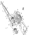
- FIG. 1 there is shown an optical fiber duplex connector assembly 11 in accordance with a preferred embodiment of the invention.
- Assembly 11 includes a first housing 82 which is adapted for housing a pair of singular, optical fiber connectors 40 and 42 therein.
- each connector 40 and 42 includes an outer (third) housing 47 (defined below) into which is inserted another (second) housing (22).
- This second housing includes an optical fiber 12 (FIG. 3), having a known ferrule 21 located on an end thereof, movably positioned therein.
- Fiber 12 is also encased with an outer sheath protector cover (or coating) 10 which provides protection for the fiber, particularly at the external locations from the invention.
- the invention to be defined in greater detail hereinbelow incorporates the use of at least three separate housings which are strategically positioned in a predetermined relationship with each other to provide the unique, movable orientation taught herein such that the invention's retained third housings (each having a respective second housing therein), as movably retained in a common (first) housing, are capable of being precisely aligned with a suitable common housing such as an interim adapter (defined above) or an optelectronic module type of housing such as a shroud or housing extension (as defined in U.S. Patent 5,005,939 and illustrated therein by the numeral 81). Such a shroud is also illustrated in FIG. 6 (e.g., no. 99), and will be further described below.
- FIG. 1 there is shown the aforementioned first housing 82 in accordance with a preferred embodiment of the invention.
- Housing 82 is specifically designed for housing the aforementioned two optical fiber connectors 40 and 42 of the push-pull variety therein in such a manner that these connectors are each movable during subsequent positioning within the corresponding common connector housing (e.g. adapter or shroud).
- push-pull as used herein is meant to define a form of optical fiber connector which is capable of being inserted within a corresponding housing or the like so as to be in alignment therein with another optical device (e.g., a module such as in U.S Patent 5,005,939 or, alternatively, another connector).
- Such connectors are known in the art, with several types currently available on the marketplace.
- each connector includes therein at least one optical fiber and attached ferrule and is adapted for being aligned with another, substantially similiar connector also including therein a corresponding optical fiber or, if the connector is to be aligned with a module, a transmitter or photodiode such as defined in U.S. Patent 5,005,939.
- the function of assembly 11 is thus to precisely align respective optical fiber connectors (40,42) so that the individual optical fibers therein are precisely aligned, both angularly and axially, with respective optoelectronic receiving structures.
- Such alignment is attained in an independent manner and, significantly, assures final positioning in a facile manner using a minimum of force.
- housing 82 the function of housing 82 is to positively retain connectors 40 and 42 in side-by-side orientation such that these two, now forming what may also be referred to as a duplex arrangement, may be simultaneously inserted within a common connector housing such as housing 99 (FIG. 6).
- the invention as defined herein uniquely enables these individual connectors 40 and 42, while being positioned in this side-by-side relationship, to be moved relative to each other in, significantly, at least three different directions (to be explained below). Such movement facilitates positioning of each duplex arrangement, thereby readily compensating for manufacturing tolerances within the outer housings of each singular connector and/or the common connector housing into which these will be positioned.
- first housing 82 is shown to include first and second chamber portions 87 and 88, within a base portion 80, each chamber portion of a substantially rectangular configuration, and designed for retaining a respective one of the connectors 40 and 42.
- chamber 87 is particularly adapted for retaining connector 40 while second chamber 88 is similarly adapted for retaining connector 42.
- Such retention is further assured by the provision of a plurality of upstanding rib members 89 on opposing internal walls of each rectangular shaped chamber. Although a total of four rib members 89 are depicted in FIG. 1 for each chamber, it is understood that only two of these per chamber are aligned within corresponding, mating grooves 43 located in opposing sides of each connector.
- the two rib members 89 per chamber that are slidably positioned within the third housing grooves 43 are those at the front (forward) end of housing 82, this end understandably being that to the lower left in FIG. 1.
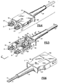
- the rear pair of ribs 89 per chamber may serve as rear stops for engaging the back surface 90 of the third housing 47, as shown, for example, in FIG. 2.
- each third housing 47 is less in height and width than the corresponding internal dimensions of the respective chamber portions 87 and 88.
- the dimensioning of the aforementioned third housing grooves 43 is greater in width and depth than the corresponding width and depth of the aforementioned first housing rib members 89, which are slidably positioned within grooves 43, when such housings are positioned into chamber portions 87 and 88, respectively.
- housings 47 may become angularly displaced relative to the also substantially planar bottom wall of housing 82.
- these dimensional variations enabling the three different directions of movement and angular displacement as defined, also enable rotational movement of third housing 47, albeit on a relatively limited basis. Such rotational movement is represented in FIG. 2 ("R").
- each chamber member 87 and 88 as shown herein is of rectangular configuration (in side view and in cross-section), this is not meant to limit the invention in that other configurations are possible. In the embodiment as depicted herein, however, such a configuration is preferred to better accomodate the similar configuration for the housings (47) of each optical fiber connector.
- singular optical fiber connectors such as connectors 40 and 42, these include the aforementioned outer, third housing 47 which serves to contain the aforementioned second housing 22, which serves in turn to contain optical fiber 12 (FIG. 3) therein.
- the remainder of the optical fiber e.g., the designed cladding and other protective elements (e.g., protective cover 10) as known in the art).
- one optical fiber connector capable of being successfully retained by the common, first housing 82, along with another, similar such connector, is a modified version of a simplex connector housing currently available on the market from the Nippon Telegraph and Telephone International Corporation, Tokyo, Japan, and referred to as a SC-01 connector.
- This modified housing includes the aforementioned grooves 43 in its external surface.
- Such connectors each include the described, rectangular (in cross section) housing 22, including therein the defined ceramic ferrule (see also below). Very low return loss is possible when using such connectors.
- the housings 22 used in these connectors typically have a length of only about one inch and cross-sectional dimensions of only about 0.35 inch by about 0.29 inch.
- Such a housing is also capable of including either single mode or multimode fibers.
- a preferred plastic material used for the outer housing 22 is polybutylene terephthalate, having a twenty percent glass fiber reinforcement.
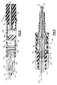
- each housing 22 also includes a ferrule 21 (see also FIG. 3) positioned therein and designed for accomodating the respective end of optical fiber 12.
- a ferrule 21 see also FIG. 3
- Each such connector also includes the aforementioned extending protective cover portion 10. It is understood that the invention is not limited to positive retention of the aforementioned optical connectors but that other connectors, including those having different external configurations, (e.g. round, hexagonal, etc.) may also be effectively retained, aligned and positioned using the teachings herein.
- ferrule 21 is retained within housing 22 in such a manner so as to permit concentric movement of the protruding end thereof around its' centerline ("CL" in FIGS. 2 and 3).
- spring means 44 (FIG. 3) for biasing the ferrule in a lateral direction (to the left in FIG. 3) along this centerline.
- FIG. 3 shows a concentrically formed spring 44 surrounding a rear section 45 of ferrule 21, thus providing this bias means for the ferrule.
- This is not meant to limit the invention, however, in that other constructions(e.g. resilient foam or rubber) are possible to accomplish said biasing.
- Third housing (47) is preferably of plastic material, and more preferably, polybutylene terephthalate. Other plastic materials are of course acceptable.
- the external dimensions of each second housing 22 (height and width) is such that it can be positioned inside the respective third housing 47 for movement therein.
- Protruding vertical rib members 23 on opposing sides of the second housing are of such projection as to permit entry into the third housing and also to extend into internal grooves 46 (FIG. 1) designed into respective, internal opposing sides of the respective third housing.
- these receiving grooves 46 are of a greater width than the corresponding ribs 23. More specifically, each groove 46 is of a design such that its length accommodates lateral movement of rib 23 (and thus housing 22) of about 0.065 inches. Such an arrangement provides for retention of each second housing while enabling lateral movement of this housing along the centerline of the mated second and third housings.
- first housing 82 is shown to comprise a slot 85 located at the rear of the base portion (to the right in FIG. 1) into which is positioned a grooved portion 17 of a protective boot 14.
- the boot surrounds the two optical fiber cables entering the first housing 82 with a tapered sheath portion 15 projecting outward from the first housing 82 along part of the optical fiber cables and a retainer portion 19 residing within the first housing 82, effectively providing retention and protection of the aforementioned cables.
- the cross-sectional thickness of the boot material is greater at the retainer portion, graduating in a decreasing mode from retainer to end of sheath where the optical fiber cables exit, as seen in the partial cross-section depicted in FIG. 2.
- This tapered configuration protects the optical fiber cables from damage as a result of extreme bending by substantially preventing such bending.
- Boot 14 is thus flexible, and is preferably of plastic or rubber material for this purpose.
- the completed optical fiber duplex connector assembly 11 can now be mated with a common housing such as defined above, one example being a shroud 99 as shown in FIG. 6.
- the defined optical fiber containing ferrules are thus mated in an abutting relationship with respective opposing optical elements (e.g., transmitter and receiver), which may be contained in chambers within the shroud, or may be mated thereto, as defined, for example, in U.S. Patent 5,005,939.
- respective opposing optical elements e.g., transmitter and receiver
- the instant invention facilitates this alignment and positioning by enabling the paired optical fiber connectors to move independently in at least three different forms of movement within the larger, first housing 82 so as to possess relative freedom of movement therebetween immediately prior to insertion within a common housing such as shroud 99. It is further understood from the foregoing that it is also readily possible to provide a combination of other movements as defined herein. For example, the invention may also allow both lateral and vertical movement of the second housings 22 (FIG. 1), as well as concentric movement of the respective ferrules (FIG. 3) to occur simultaneously. Thus, a variety of combinations of movement are possible using the unique teachings of the invention.
- connector 11 also includes a cover portion 84, as shown in FIGS. 1 and 4.
- Cover 84 includes horizontal rib members 93 designed for being slidably positioned within grooves 95 contained in external walls of base portion 80 (FIGS. 1 and 5).
- Cover 84 further includes a pair of projecting tabs 83 (FIG. 1) designed for being position within respective grooves 81 located within the rear external wall 101 (to the right in FIG. 1) of base portion 80. Positioning rib members 93 into grooves 95 and sliding the cover to position the projecting tabs 83 into the grooves 81, locates the cover portion 84 in proper alignment onto base portion 80.
- Retention of the cover 84 onto the aforementioned base portion 80 is accomplished using a downward projecting tab (91) (FIG. 2) from cover 84, which tab inserts within a groove 86 (FIG. 5) provided in base portion 80.
- a downward projecting tab (91) FIG. 2
- cover 84 Such positioning is arranged with the "sliding" of the cover 84, from the front of the base portion 80, towards the rear of the base portion (from left to right in FIG. 1), positioning projecting tabs 83 into grooves 81 and projecting tab 91 into groove 86, with a "snap".
- Such an arrangement significantly, enables facile cover removal (e.g., for repair, or replacement with additional cover configurations), requiring only slight cover lifting (to effect tab release) and reverse sliding of the cover (to the front of base 80).
- Such cover replacement provides versatility for assembly 11 in that it enables positioning thereof within receiving housings of different designs. Of further significance is the ease of insertion/removal of individual connectors 40 and 42 to/from base housing 80 after cover 84 has been removed. (These connectors need only be lifted vertically.) Design of protective boot 15 also enables facile insertion/removal of the boot, adding further versatility to the invention, and also expediting removal of connectors 40 and 42.
- optical fiber duplex connector assembly wherein a common, first housing is utilized to hold two individual optical fiber connectors in a substantially side-by-side relationship while still enabling these connectors to exhibit relative freedom of movement therebetween such that this combined assembly can be more readily positioned within a common housing connector assembly or the like.
- the invention as defined herein is of relatively simple construction and can be readily adapted to many existing optical fiber connector designs. It may also be produced in a relatively inexpensive manner, and is readily adaptable to mass production. Of further significance, the invention is readily capable of being at least partially disassembled (removal of the cover portion) to enable facile separation of the internal optical connectors thereof (e.g., in the event that individual positioning of said connectors within respective receiving structures is desired).
Landscapes
- Physics & Mathematics (AREA)
- General Physics & Mathematics (AREA)
- Optics & Photonics (AREA)
- Mechanical Coupling Of Light Guides (AREA)
Applications Claiming Priority (2)
| Application Number | Priority Date | Filing Date | Title |
|---|---|---|---|
| US07/874,162 US5315679A (en) | 1992-04-27 | 1992-04-27 | Optical fibers duplex connector assembly |
| US874162 | 1992-04-27 |
Publications (2)
| Publication Number | Publication Date |
|---|---|
| EP0567809A2 true EP0567809A2 (fr) | 1993-11-03 |
| EP0567809A3 EP0567809A3 (en) | 1993-12-15 |
Family
ID=25363121
Family Applications (1)
| Application Number | Title | Priority Date | Filing Date |
|---|---|---|---|
| EP19930105642 Withdrawn EP0567809A3 (en) | 1992-04-27 | 1993-04-06 | Optical fiber duplex connector assembly |
Country Status (3)
| Country | Link |
|---|---|
| US (1) | US5315679A (fr) |
| EP (1) | EP0567809A3 (fr) |
| JP (1) | JPH087308B2 (fr) |
Cited By (8)
| Publication number | Priority date | Publication date | Assignee | Title |
|---|---|---|---|---|
| WO1994017433A1 (fr) * | 1993-01-26 | 1994-08-04 | Siemens Aktiengesellschaft | Support |
| EP0689069A1 (fr) * | 1994-06-24 | 1995-12-27 | AT&T Corp. | Connecteur à fibre optique |
| DE19507669A1 (de) * | 1995-03-06 | 1996-09-12 | Telegaertner Geraetebau Gmbh | Optischer Mehrfach-Steckverbinder, insbesondere für Rund- oder Zip-cord-Kabel |
| NL9500327A (nl) * | 1995-02-21 | 1996-10-01 | Framatome Connectors Belgium | Connector voor één of meer optische geleiders. |
| US5613025A (en) * | 1995-07-13 | 1997-03-18 | Grois; Igor | Adapter assembly for fiber optic connectors |
| EP0819960A3 (fr) * | 1996-07-15 | 1998-12-30 | Seiko Instruments Inc. | Connecteurs universels pour fibres optiques et leurs fiches de base |
| EP1168018A3 (fr) * | 2000-06-23 | 2004-12-01 | Molex Incorporated | Connecteur pour fibres optiques |
| EP1168016A3 (fr) * | 2000-06-23 | 2005-04-27 | Molex Incorporated | Connecteur pour fibres optiques |
Families Citing this family (109)
| Publication number | Priority date | Publication date | Assignee | Title |
|---|---|---|---|---|
| USRE40150E1 (en) | 1994-04-25 | 2008-03-11 | Matsushita Electric Industrial Co., Ltd. | Fiber optic module |
| US5475781A (en) * | 1994-09-15 | 1995-12-12 | Chang; Peter C. | Optical fiber connector assembly with loop-back structure |
| US5717533A (en) | 1995-01-13 | 1998-02-10 | Methode Electronics Inc. | Removable optoelectronic module |
| US6220878B1 (en) | 1995-10-04 | 2001-04-24 | Methode Electronics, Inc. | Optoelectronic module with grounding means |
| US5553180A (en) * | 1995-01-17 | 1996-09-03 | Molex Incorporated | Adapter assembly for fiber optic connectors |
| EP0758098A1 (fr) * | 1995-08-09 | 1997-02-12 | Molex Incorporated | Adaptateur pour connecteurs à fibres optiques |
| DE19844688A1 (de) * | 1998-09-29 | 2000-03-30 | Delphi Automotive Systems Gmbh | Optischer Verbinder |
| EP1145061B1 (fr) | 1998-12-22 | 2003-04-16 | Rako Electronic Data Technology GmbH | Connecteur pour guides optiques avec boitier de connexion |
| DE19900781C2 (de) * | 1998-12-22 | 2001-11-29 | Cla Son Leasing Und Holding Gm | Stecker für Lichtwellenleiter mit einem Steckergehäuse |
| US6220873B1 (en) | 1999-08-10 | 2001-04-24 | Stratos Lightwave, Inc. | Modified contact traces for interface converter |
| US6511230B1 (en) | 2000-02-04 | 2003-01-28 | Panduit Corp. | Fiber optic connection system |
| DE10020675A1 (de) * | 2000-04-27 | 2001-10-31 | Delphi Tech Inc | Verbindungsmodul |
| US6572276B1 (en) | 2000-11-21 | 2003-06-03 | Euromicron Werkezeuge Gmbh | Plug for fiber optic cables with a plug housing |
| US6942395B1 (en) | 2001-01-29 | 2005-09-13 | Jds Uniphase Corporation | Method and apparatus of pull-lever release for fiber optic modules |
| US6863448B2 (en) | 2001-04-14 | 2005-03-08 | Jds Uniphase Corporation | Method and apparatus for push button release fiber optic modules |
| US6851867B2 (en) | 2001-04-14 | 2005-02-08 | Jds Uniphase Corporation | Cam-follower release mechanism for fiber optic modules with side delatching mechanisms |
| US6994478B1 (en) | 2001-04-14 | 2006-02-07 | Jds Uniphase Corporation | Modules having rotatable release and removal lever |
| US6796715B2 (en) | 2001-04-14 | 2004-09-28 | E20 Communications, Inc. | Fiber optic modules with pull-action de-latching mechanisms |
| US6692159B2 (en) | 2001-04-14 | 2004-02-17 | E20 Communications, Inc. | De-latching mechanisms for fiber optic modules |
| US6840680B1 (en) | 2001-04-14 | 2005-01-11 | Jds Uniphase Corporation | Retention and release mechanisms for fiber optic modules |
| US6755576B2 (en) * | 2001-11-05 | 2004-06-29 | International Business Machines Corporation | Multiple array optoelectronic connector with integrated latch |
| US6666589B2 (en) | 2001-11-05 | 2003-12-23 | International Business Machines Corporation | Internal EMI shield for multiple array optoelectronic devices |
| US6634803B2 (en) | 2001-11-05 | 2003-10-21 | International Business Machines Corporation | External EMI shield for multiple array optoelectronic devices |
| TW532482U (en) * | 2001-11-15 | 2003-05-11 | Hon Hai Prec Ind Co Ltd | Device for preventing the fiber from being bent |
| USD474743S1 (en) | 2002-07-10 | 2003-05-20 | Hon Hai Precision Ind. Co., Ltd. | Optical fiber adapter |
| US7118281B2 (en) | 2002-08-09 | 2006-10-10 | Jds Uniphase Corporation | Retention and release mechanisms for fiber optic modules |
| US6870996B2 (en) * | 2002-09-19 | 2005-03-22 | 3M Innovative Properties Company | Optical fiber plug including fiber positioning holder |
| US6962445B2 (en) | 2003-09-08 | 2005-11-08 | Adc Telecommunications, Inc. | Ruggedized fiber optic connection |
| JP4665528B2 (ja) * | 2004-07-06 | 2011-04-06 | 富士ゼロックス株式会社 | 光信号伝送装置 |
| NL1026842C2 (nl) * | 2004-08-13 | 2006-02-14 | Framatome Connectors Int | Kabelconnector. |
| US7712979B2 (en) * | 2005-06-28 | 2010-05-11 | Sumiden High Precision Co., Ltd. | Optical adapter |
| US20070025666A1 (en) * | 2005-07-28 | 2007-02-01 | Sumiden High Precision Co., Ltd. | Optical connector plug |
| US20080145005A1 (en) * | 2006-12-15 | 2008-06-19 | Masahiro Shibata | Optical communication module and optical sub-assembly |
| US7572065B2 (en) * | 2007-01-24 | 2009-08-11 | Adc Telecommunications, Inc. | Hardened fiber optic connector |
| US7591595B2 (en) * | 2007-01-24 | 2009-09-22 | Adc Telelcommunications, Inc. | Hardened fiber optic adapter |
| US7744286B2 (en) | 2007-12-11 | 2010-06-29 | Adc Telecommunications, Inc. | Hardened fiber optic connection system with multiple configurations |
| US8452148B2 (en) | 2008-08-29 | 2013-05-28 | Corning Cable Systems Llc | Independently translatable modules and fiber optic equipment trays in fiber optic equipment |
| US11294136B2 (en) | 2008-08-29 | 2022-04-05 | Corning Optical Communications LLC | High density and bandwidth fiber optic apparatuses and related equipment and methods |
| ATE534049T1 (de) | 2009-02-24 | 2011-12-15 | Ccs Technology Inc | Haltevorrichtung für ein kabel oder eine anordnung zur verwendung mit einem kabel |
| US8699838B2 (en) | 2009-05-14 | 2014-04-15 | Ccs Technology, Inc. | Fiber optic furcation module |
| US9075216B2 (en) | 2009-05-21 | 2015-07-07 | Corning Cable Systems Llc | Fiber optic housings configured to accommodate fiber optic modules/cassettes and fiber optic panels, and related components and methods |
| US8538226B2 (en) | 2009-05-21 | 2013-09-17 | Corning Cable Systems Llc | Fiber optic equipment guides and rails configured with stopping position(s), and related equipment and methods |
| US8712206B2 (en) | 2009-06-19 | 2014-04-29 | Corning Cable Systems Llc | High-density fiber optic modules and module housings and related equipment |
| WO2010148336A1 (fr) | 2009-06-19 | 2010-12-23 | Corning Cable Systems Llc | Appareils à fibres optiques à large bande et à densité élevée et équipement et procédés associés |
| US8625950B2 (en) | 2009-12-18 | 2014-01-07 | Corning Cable Systems Llc | Rotary locking apparatus for fiber optic equipment trays and related methods |
| US8593828B2 (en) | 2010-02-04 | 2013-11-26 | Corning Cable Systems Llc | Communications equipment housings, assemblies, and related alignment features and methods |
| US8913866B2 (en) | 2010-03-26 | 2014-12-16 | Corning Cable Systems Llc | Movable adapter panel |
| AU2011265751B2 (en) | 2010-04-16 | 2015-09-10 | Corning Optical Communications LLC | Sealing and strain relief device for data cables |
| EP2381284B1 (fr) | 2010-04-23 | 2014-12-31 | CCS Technology Inc. | Dispositif de distribution à fibre optique encastré dans le sol |
| US8705926B2 (en) | 2010-04-30 | 2014-04-22 | Corning Optical Communications LLC | Fiber optic housings having a removable top, and related components and methods |
| US9075217B2 (en) | 2010-04-30 | 2015-07-07 | Corning Cable Systems Llc | Apparatuses and related components and methods for expanding capacity of fiber optic housings |
| US8660397B2 (en) | 2010-04-30 | 2014-02-25 | Corning Cable Systems Llc | Multi-layer module |
| US9632270B2 (en) | 2010-04-30 | 2017-04-25 | Corning Optical Communications LLC | Fiber optic housings configured for tool-less assembly, and related components and methods |
| US8879881B2 (en) | 2010-04-30 | 2014-11-04 | Corning Cable Systems Llc | Rotatable routing guide and assembly |
| US9519118B2 (en) | 2010-04-30 | 2016-12-13 | Corning Optical Communications LLC | Removable fiber management sections for fiber optic housings, and related components and methods |
| US9720195B2 (en) | 2010-04-30 | 2017-08-01 | Corning Optical Communications LLC | Apparatuses and related components and methods for attachment and release of fiber optic housings to and from an equipment rack |
| US8718436B2 (en) | 2010-08-30 | 2014-05-06 | Corning Cable Systems Llc | Methods, apparatuses for providing secure fiber optic connections |
| US9279951B2 (en) | 2010-10-27 | 2016-03-08 | Corning Cable Systems Llc | Fiber optic module for limited space applications having a partially sealed module sub-assembly |
| US9116324B2 (en) | 2010-10-29 | 2015-08-25 | Corning Cable Systems Llc | Stacked fiber optic modules and fiber optic equipment configured to support stacked fiber optic modules |
| US8662760B2 (en) * | 2010-10-29 | 2014-03-04 | Corning Cable Systems Llc | Fiber optic connector employing optical fiber guide member |
| CA2819235C (fr) | 2010-11-30 | 2018-01-16 | Corning Cable Systems Llc | Support de corps de fibre et dispositif de reduction des tensions |
| JP2012128341A (ja) * | 2010-12-17 | 2012-07-05 | Suncall Corp | 二芯型光コネクタ |
| WO2012106510A2 (fr) | 2011-02-02 | 2012-08-09 | Corning Cable Systems Llc | Ensembles de connecteurs de fibres optiques denses et connecteurs associés et câbles appropriés pour établir des connexions optiques pour des fonds de panier optiques dans des râteliers d'équipement |
| ES2395358B1 (es) | 2011-02-08 | 2014-04-25 | Tyco Electronics Corporation | Conectador de acción única |
| ES2402632B1 (es) | 2011-02-08 | 2014-05-14 | Tyco Electronics Raychem Bvba | Lengüeta de liberación para un conectador eléctrico y conectador eléctrico que comprende dicha lengüeta de liberación |
| WO2012151175A2 (fr) | 2011-05-04 | 2012-11-08 | The Siemon Company | Connecteur de fibre optique à changement de polarité |
| US9008485B2 (en) | 2011-05-09 | 2015-04-14 | Corning Cable Systems Llc | Attachment mechanisms employed to attach a rear housing section to a fiber optic housing, and related assemblies and methods |
| US8764308B2 (en) | 2011-06-06 | 2014-07-01 | Panduit Corp. | Duplex clip assembly for fiber optic connectors |
| WO2013003303A1 (fr) | 2011-06-30 | 2013-01-03 | Corning Cable Systems Llc | Ensembles d'équipement à fibres optiques utilisant des boîtiers hors dimensions de largeur u, et procédés associés |
| US8953924B2 (en) | 2011-09-02 | 2015-02-10 | Corning Cable Systems Llc | Removable strain relief brackets for securing fiber optic cables and/or optical fibers to fiber optic equipment, and related assemblies and methods |
| US9038832B2 (en) | 2011-11-30 | 2015-05-26 | Corning Cable Systems Llc | Adapter panel support assembly |
| US8727638B2 (en) * | 2011-12-21 | 2014-05-20 | Alliance Fiber Optic Products Co., Ltd. | Fiber channel-inter changeable fiber optic connector |
| CN103257407B (zh) | 2012-02-20 | 2015-11-25 | 泰科电子(上海)有限公司 | 连接器和连接器组件 |
| US9250409B2 (en) | 2012-07-02 | 2016-02-02 | Corning Cable Systems Llc | Fiber-optic-module trays and drawers for fiber-optic equipment |
| US9042702B2 (en) | 2012-09-18 | 2015-05-26 | Corning Cable Systems Llc | Platforms and systems for fiber optic cable attachment |
| ES2551077T3 (es) | 2012-10-26 | 2015-11-16 | Ccs Technology, Inc. | Unidad de gestión de fibra óptica y dispositivo de distribución de fibra óptica |
| EP2759859B1 (fr) * | 2013-01-29 | 2018-05-16 | Tyco Electronics Nederland B.V. | Support de guidage et kit pour terminer un câble de transmission |
| US8985862B2 (en) | 2013-02-28 | 2015-03-24 | Corning Cable Systems Llc | High-density multi-fiber adapter housings |
| US9461374B2 (en) * | 2013-03-15 | 2016-10-04 | Molex, Llc | Electrical connector assembly and connecting member thereof |
| US10444443B2 (en) | 2013-06-27 | 2019-10-15 | CommScope Connectivity Belgium BVBA | Fiber optic cable anchoring device for use with fiber optic connectors and methods of using the same |
| EP3907541B1 (fr) | 2014-01-13 | 2023-12-27 | CommScope Telecommunications (Shanghai) Co. Ltd. | Connecteur à fibre optique |
| JP6342859B2 (ja) * | 2015-08-18 | 2018-06-13 | 矢崎総業株式会社 | 光コネクタ |
| US9989712B1 (en) * | 2017-03-20 | 2018-06-05 | Senko Advanced Components, Inc | MPO connector assembly with push-pull tab |
| WO2018226959A1 (fr) | 2017-06-07 | 2018-12-13 | Commscope Technologies Llc | Adaptateur et cassette de fibre optique |
| EP3646092B1 (fr) | 2017-06-28 | 2021-11-24 | Corning Research & Development Corporation | Connecteurs de fibres optiques compacts |
| US10718911B2 (en) | 2017-08-24 | 2020-07-21 | Senko Advanced Components, Inc. | Ultra-small form factor optical connectors using a push-pull boot receptacle release |
| US10281668B2 (en) | 2017-07-14 | 2019-05-07 | Senko Advanced Components, Inc. | Ultra-small form factor optical connectors |
| US12001064B2 (en) | 2017-07-14 | 2024-06-04 | Senko Advanced Components, Inc. | Small form factor fiber optic connector with multi-purpose boot |
| US11822133B2 (en) | 2017-07-14 | 2023-11-21 | Senko Advanced Components, Inc. | Ultra-small form factor optical connector and adapter |
| US11002923B2 (en) | 2017-11-21 | 2021-05-11 | Senko Advanced Components, Inc. | Fiber optic connector with cable boot release having a two-piece clip assembly |
| CN115201974B (zh) * | 2017-12-19 | 2024-04-30 | 美国康涅克有限公司 | 具有推拉极性机构和载体的微型双工连接器 |
| EP3776038B1 (fr) | 2018-03-28 | 2024-07-03 | Senko Advanced Components Inc. | Connecteur de fibre optique à petit facteur de forme avec manchon multifonctionnel |
| US11409054B2 (en) * | 2018-05-11 | 2022-08-09 | Us Conec Ltd. | Method and apparatus for assembling uniboot fiber optic connectors |
| US11073664B2 (en) | 2018-08-13 | 2021-07-27 | Senko Advanced Components, Inc. | Cable boot assembly for releasing fiber optic connector from a receptacle |
| US10921530B2 (en) | 2018-09-12 | 2021-02-16 | Senko Advanced Components, Inc. | LC type connector with push/pull assembly for releasing connector from a receptacle using a cable boot |
| US10921531B2 (en) | 2018-09-12 | 2021-02-16 | Senko Advanced Components, Inc. | LC type connector with push/pull assembly for releasing connector from a receptacle using a cable boot |
| CN112955797B (zh) | 2018-09-12 | 2022-11-11 | 扇港元器件股份有限公司 | 具有用于利用缆线护套将连接器从插座释放的夹式推/拉舌片的lc型连接器 |
| US11340406B2 (en) | 2019-04-19 | 2022-05-24 | Senko Advanced Components, Inc. | Small form factor fiber optic connector with resilient latching mechanism for securing within a hook-less receptacle |
| CN114026480B (zh) | 2019-06-13 | 2023-05-26 | 扇港元器件有限公司 | 用于从插座端口释放光纤连接器的杆驱动闩锁臂和使用方法 |
| EP4052077A1 (fr) | 2019-12-18 | 2022-09-07 | US Conec, Ltd | Connecteur uniboot à ports multiples pour boîtiers de connecteur à fibres multiples |
| US12345925B2 (en) | 2020-05-29 | 2025-07-01 | Commscope Technologies Llc | Telecommunications connector with latch release mechanism |
| US11604320B2 (en) | 2020-09-30 | 2023-03-14 | Corning Research & Development Corporation | Connector assemblies for telecommunication enclosures |
| CN116601834A (zh) | 2020-10-30 | 2023-08-15 | 康宁研究与开发公司 | 具有防风雨套环的光纤连接器 |
| US11994722B2 (en) | 2020-11-30 | 2024-05-28 | Corning Research & Development Corporation | Fiber optic adapter assemblies including an adapter housing and a locking housing |
| US11927810B2 (en) | 2020-11-30 | 2024-03-12 | Corning Research & Development Corporation | Fiber optic adapter assemblies including a conversion housing and a release member |
| US11880076B2 (en) | 2020-11-30 | 2024-01-23 | Corning Research & Development Corporation | Fiber optic adapter assemblies including a conversion housing and a release housing |
| KR102505100B1 (ko) * | 2021-02-09 | 2023-03-02 | 주식회사 센서뷰 | 전기 커넥터 |
| US12523821B2 (en) | 2021-04-08 | 2026-01-13 | Commscope Technologies Llc | Telecommunications connector with latch release mechanism |
| USD1060249S1 (en) * | 2021-08-30 | 2025-02-04 | Corning Research & Development Corporation | Multifiber connector for making optical connections |
Family Cites Families (17)
| Publication number | Priority date | Publication date | Assignee | Title |
|---|---|---|---|---|
| US4167303A (en) * | 1977-07-28 | 1979-09-11 | Amp Incorporated | Light transmitting fiber cable connector |
| US4291943A (en) * | 1977-08-05 | 1981-09-29 | Minnesota Mining And Manufacturing Company | Connector for optical fiber cables |
| US4611887A (en) * | 1983-02-24 | 1986-09-16 | Amp Incorporated | Fiber optic connector assembly and wall outlet thereof |
| JPS60107808U (ja) * | 1983-12-27 | 1985-07-22 | デユポン ジヤパン リミテツド | 光フアイバ用の複式コネクタ |
| US4687291A (en) * | 1984-06-08 | 1987-08-18 | Amp Incorporated | Duplex electro-fiber connector assembly |
| US4744629A (en) * | 1985-08-16 | 1988-05-17 | Augat Inc. | Multifiber optical cable connector |
| JPS6276302U (fr) * | 1985-10-31 | 1987-05-15 | ||
| JPH077139B2 (ja) * | 1985-12-24 | 1995-01-30 | 日本電信電話株式会社 | 浮動ホルダ型光コネクタ |
| US4863235A (en) * | 1986-07-21 | 1989-09-05 | American Telephone And Telegraph Company, At&T Bell Laboratories | Connector for optical fiber cable |
| US4787706A (en) * | 1987-02-03 | 1988-11-29 | American Telephone And Telegraph Company, At&T Bell Laboratories | Duplex optical fiber connector |
| JPH0522885Y2 (fr) * | 1987-10-09 | 1993-06-11 | ||
| US4895425A (en) * | 1988-02-26 | 1990-01-23 | Nippon Telegraph And Telephone Corporation | Plug-in optical fiber connector |
| US4953929A (en) * | 1989-07-21 | 1990-09-04 | International Business Machines | Fiber optic connector assembly and adapter for use therewith |
| US4979792A (en) * | 1989-08-21 | 1990-12-25 | Amp Incorporated | Means for keeping keying elements with a connector assembly |
| US5016968A (en) * | 1989-09-27 | 1991-05-21 | At&T Bell Laboratories | Duplex optical fiber connector and cables terminated therewith |
| US5123071A (en) * | 1990-03-09 | 1992-06-16 | Amp Incorporated | Overconnector assembly for a pair of push-pull coupling type optical fiber connectors |
| US5005939A (en) * | 1990-03-26 | 1991-04-09 | International Business Machines Corporation | Optoelectronic assembly |
-
1992
- 1992-04-27 US US07/874,162 patent/US5315679A/en not_active Expired - Lifetime
-
1993
- 1993-03-12 JP JP5051178A patent/JPH087308B2/ja not_active Expired - Fee Related
- 1993-04-06 EP EP19930105642 patent/EP0567809A3/en not_active Withdrawn
Cited By (14)
| Publication number | Priority date | Publication date | Assignee | Title |
|---|---|---|---|---|
| US5574812A (en) * | 1993-01-26 | 1996-11-12 | Siemens Aktiengesellscnaft | Holder arrangement for optical connectors or the like |
| WO1994017433A1 (fr) * | 1993-01-26 | 1994-08-04 | Siemens Aktiengesellschaft | Support |
| EP0689069A1 (fr) * | 1994-06-24 | 1995-12-27 | AT&T Corp. | Connecteur à fibre optique |
| NL9500327A (nl) * | 1995-02-21 | 1996-10-01 | Framatome Connectors Belgium | Connector voor één of meer optische geleiders. |
| DE19507669C2 (de) * | 1995-03-06 | 1998-10-08 | Telegaertner Geraetebau Gmbh | Optischer Mehrfach-Steckverbinder, insbesondere für Rund- oder Zip-cord-Kabel |
| DE19507669A1 (de) * | 1995-03-06 | 1996-09-12 | Telegaertner Geraetebau Gmbh | Optischer Mehrfach-Steckverbinder, insbesondere für Rund- oder Zip-cord-Kabel |
| US5613025A (en) * | 1995-07-13 | 1997-03-18 | Grois; Igor | Adapter assembly for fiber optic connectors |
| EP0819960A3 (fr) * | 1996-07-15 | 1998-12-30 | Seiko Instruments Inc. | Connecteurs universels pour fibres optiques et leurs fiches de base |
| US6151432A (en) * | 1996-07-15 | 2000-11-21 | Seiko Instruments Inc. | Universal optical fiber connectors and basic plugs thereof |
| US6224270B1 (en) | 1996-07-15 | 2001-05-01 | Seiko Instruments Inc. | Universal optical fiber connectors and basic plugs thereof |
| US6533468B2 (en) | 1996-07-15 | 2003-03-18 | Seiko Instruments Inc. | Universal optical fiber connectors and basic plugs thereof |
| EP1168018A3 (fr) * | 2000-06-23 | 2004-12-01 | Molex Incorporated | Connecteur pour fibres optiques |
| EP1168016A3 (fr) * | 2000-06-23 | 2005-04-27 | Molex Incorporated | Connecteur pour fibres optiques |
| EP1752805A3 (fr) * | 2000-06-23 | 2007-03-21 | Molex Incorporated | Connecteur pour fibres optiques |
Also Published As
| Publication number | Publication date |
|---|---|
| US5315679A (en) | 1994-05-24 |
| EP0567809A3 (en) | 1993-12-15 |
| JPH087308B2 (ja) | 1996-01-29 |
| JPH0618749A (ja) | 1994-01-28 |
Similar Documents
| Publication | Publication Date | Title |
|---|---|---|
| US5315679A (en) | Optical fibers duplex connector assembly | |
| EP0408852B1 (fr) | Assemblage de connecteurs pour fibres optiques et adaptateur pour celui-ci | |
| US12013578B2 (en) | Multifiber fiber optic connectors, cable assemblies and methods of making the same | |
| JP3505237B2 (ja) | プラグ保持装置及びそれを使用するデュプレックス型光コネクタ | |
| EP0758099B1 (fr) | Assemblage avec adaptateur pour connecteurs à fibres optiques | |
| EP0610676B1 (fr) | Dispositif de couplage des fibres optiques et système opto-électronique l'utilisant | |
| CA1308280C (fr) | Connecteur de fibres optiques duplex | |
| US6682228B2 (en) | Connector housing for fiber-optic module | |
| EP1148366B1 (fr) | Connecteur à fibre optique avec ajustement d'excentricité | |
| US4872736A (en) | Connector assembly having a latching mechanism | |
| KR100248971B1 (ko) | 광 섬유 커넥터용 어댑터 조립체 | |
| EP0723169B1 (fr) | Ensemble adaptateur pour des fiches à fibre optique | |
| US20210191060A1 (en) | Flexible boot with replaceable repositioning device therein | |
| US11029470B2 (en) | Fiber optic adapter with dust shutter assembly for receiving a fiber optic connector | |
| US9086546B2 (en) | Connector systems having receptacle assembly and plug assembly | |
| CN100468107C (zh) | 键固光纤连接器 | |
| US20050058401A1 (en) | Keyed adapter and connector | |
| HK1011415A (en) | Adapter assembly for fiber optic connectors | |
| HK1011414B (en) | Adapter assembly for fiber optic connectors |
Legal Events
| Date | Code | Title | Description |
|---|---|---|---|
| PUAI | Public reference made under article 153(3) epc to a published international application that has entered the european phase |
Free format text: ORIGINAL CODE: 0009012 |
|
| PUAL | Search report despatched |
Free format text: ORIGINAL CODE: 0009013 |
|
| AK | Designated contracting states |
Kind code of ref document: A2 Designated state(s): DE FR GB |
|
| AK | Designated contracting states |
Kind code of ref document: A3 Designated state(s): DE FR GB |
|
| 17P | Request for examination filed |
Effective date: 19931227 |
|
| 17Q | First examination report despatched |
Effective date: 19950811 |
|
| 18D | Application deemed to be withdrawn |
Effective date: 19980407 |