EP0567839B1 - Electronic device for damping the fuel level indicator instrument in a vehicle tank - Google Patents
Electronic device for damping the fuel level indicator instrument in a vehicle tank Download PDFInfo
- Publication number
- EP0567839B1 EP0567839B1 EP93105986A EP93105986A EP0567839B1 EP 0567839 B1 EP0567839 B1 EP 0567839B1 EP 93105986 A EP93105986 A EP 93105986A EP 93105986 A EP93105986 A EP 93105986A EP 0567839 B1 EP0567839 B1 EP 0567839B1
- Authority
- EP
- European Patent Office
- Prior art keywords
- int
- static switch
- stage
- transducer
- output
- Prior art date
- Legal status (The legal status is an assumption and is not a legal conclusion. Google has not performed a legal analysis and makes no representation as to the accuracy of the status listed.)
- Expired - Lifetime
Links
Images



Classifications
-
- G—PHYSICS
- G01—MEASURING; TESTING
- G01F—MEASURING VOLUME, VOLUME FLOW, MASS FLOW OR LIQUID LEVEL; METERING BY VOLUME
- G01F23/00—Indicating or measuring liquid level or level of fluent solid material, e.g. indicating in terms of volume or indicating by means of an alarm
- G01F23/80—Arrangements for signal processing
- G01F23/806—Particular electronic circuits for handling non-digital processing equipment
-
- G—PHYSICS
- G01—MEASURING; TESTING
- G01F—MEASURING VOLUME, VOLUME FLOW, MASS FLOW OR LIQUID LEVEL; METERING BY VOLUME
- G01F23/00—Indicating or measuring liquid level or level of fluent solid material, e.g. indicating in terms of volume or indicating by means of an alarm
- G01F23/80—Arrangements for signal processing
Definitions
- This invention relates to an electronic damping device to be fitted to an apparatus of currently used type for indicating the fuel level in a vehicle tank.
- An instrument comprising a transducer and an analog indicator is widely used for indicating the fuel level in vehicle tanks. Such an instrument is easy to read, is highly reliable and is of low cost.
- transducers used for fuel level measurement comprise an electrical resistor in the form of a conductor spirally wound on a straight support having a length proportional to the tank height and positioned perpendicularly within the tank.
- the electrical connection facing the base is carried on a sliding contact which is free to move along the entire support but is rigid with a float.
- transducers of the so-called arm type which convert the position of an arm moved by a float into a rotation of a potentiometer.
- the invention described herein can be associated with any type of gasoline level transducer, whether of the described types or of other types based on analogous principles.
- the indicator instruments themselves mostly consist of pointer indicators operated by the interaction between permanent magnets and variable electrical fields generated by coils through which electric current flows. Instruments comprising two coils of cross-coil configuration are widely used because of their insensitivity to feed voltage variations.
- Such indicator instruments fed with the battery voltage, can be directly connected to the aforesaid analog transducers, with considerable advantages in that no calibration or mutual compensation for temperature and/or feed voltage variation is required.
- Mechanical solutions comprise either incorporating silicone friction devices into the moving parts in order to introduce controlled friction, or encapsulating the float in a container to which the liquid has access via a suitably sized hole.
- Solutions of the first type involve the serious risk of breakage of the component capsules of the friction devices with resultant dispersion of foreign matter into fuel, whereas solutions of the second type, although considerably reducing the phenomenon, do not eliminate it totally. For this, small-dimension holes would be required, but these would present filling problems and could be easily clogged by the debris present on the tank base.
- a damping circuit connected to the transducer output is switched out of circuit during an initial period after switching on the ignition, so that a direct reading is available.
- signal values are averaged at longer time intervals when the liquid surface is unstable than when it is stable.
- EP-A-0275240 the effects of agitation of the fuel in the tank is obviated by calculation of weighted average values.
- An object of the present invention is to provide an apparatus for indicating the fuel level in a vehicle tank of the type and for the applications stated heretofore, which reduces the problem of oscillation of the indicator instrument to a very low level, and which allows temperature and/or feed voltage variations to be directly compensated between the transducer and the indicator.
- a further object of the present invention is to provide an apparatus which does not require setting, which is insensitive to feed voltage variations, and which maintains the float transfer characteristics unaltered.
- an electronic damping device for an apparatus for indicating the fuel level in a vehicle tank, essentially comprising an electrical level transducer located in said fuel-containing vehicle tank, an indicator device controlled by an electrical voltage and an electronic circuit comprising an input towards said transducer and an output towards said indicator device, wherein said electronic circuit comprises a first static switch connected in series between said input and said output, a second static switch which connects to said input a resistive-capacitive network consisting of a resistor and a capacitor connected in series, a third static switch which connects said capacitor to said output via an adaptive node, and a square wave generator with an ON period which is short relative to its OFF period, said square wave generator being connected to the control electrodes of said static switches in such a manner as to close said first and said second static switch and to open said third static switch during the ON stage and, complementarily, to open said first and said second static switch and to close said third static switch during the OFF stage.
- Figure 1 shows an apparatus 11 comprising an electronic circuit indicated overall by 12, an indicator device S and a transducer Rx.
- the transducer Rx is of any known type comprising an electrical resistor which varies with fuel level.
- the indicator device S consists of two cross-coils with their axes at 90° to each other.
- the two magnetic fields generated by the currents which operate the indicator give rise to a resultant force which acts on a suitably magnetized armature.
- the indicator device S is powered by the direct current battery voltage Vb.
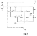
- the electronic circuit 12 comprises three static switches Int-1, Int-2 and Int-3, a resistive-capacitive network composed of a resistor R and a capacitor C, an adaptive node Op and a square wave generator Os.
- the generator Os generates a square wave which by way of non-limiting example lasts about 15 ms with an ON time of 1 ms (1/15 duty cycle). This signal is fed to the control electrode of Int-1 and Int-2 and, after electrical inversion by a NOT element Not-1, to control electrode of Int-3.
- Int-1 located in the connection line between the transducer Rx and the indicator device S, is closed and the indicator S is connected electrically to the transducer Rx for a time of 1 ms.
- Int-1 and Int-2 open, whereas Int-3 closes.
- the indicator support element is controlled by the voltage to which the capacitor C has been charged.
- the circuit 12 operates as follows.
- the indicator S Under stationary conditions and during the ON time the indicator S is independent of the electronic circuit 12 and its indication represents a direct reading as it is connected to the transducer Rx. During the OFF stage the voltage memorized by the capacitor C is applied to the indicator S.
- the capacitor C is able to follow with only negligible difference the variation in the voltage across the transducer Rx with time, this voltage therefore being faithfully reproduced by the indicator S.
- the voltage across the transducer Rx varies at a rate faster than that which can be followed by the capacitor C.
- the charging and discharging of the capacitor C are hindered not only by the time constant due to the series connection with the resistor R, but in particular by the fact that the capacitor is connected for only a fraction of the total time.
- the electronic circuit 12 displays a time constant much greater than that of the resistive-capacitive network RC without the need to use large-capacity capacitors, with all the practical and cost problems which this would involve.
- the circuit 12 further comprises a differentiating stage controlled by the transducer Rx via a fourth static switch Int-4.
- Said differentiating stage consists of a capacitor Cd and resistor Rd connected in series, and transfers the differentiation effect to the input of the adaptive node Op.
- the control electrode of the switch Int-4 is directly connected to the output of the square wave generator Os, as in the case of the switches Int-1 and Int-2.
- the addition of the differentiating stage is effective when the intrinsic damping of the float of the transducer Rx is adequate, such that the inherent float variations are much slower than the battery variations.
- a "reserve" warning light L is also connected to the electronic circuit 12.
- the contact W contained within the fuel level transducer is connected to the voltage divider node formed frog two resistors R1 and R2.
- the voltage divider R1-R2 is connected to one of the two inputs of a comparator Oc via a fifth static switch Int-5 in parallel with a diode D and a filter network consisting of a resistor Rw and a capacitor Cw.
- the other input of the comparator Oc is connected to a reference voltage Vref, and the output of Oc directly controls the lighting of the lamp L.
- the control electrode of the switch Int-5 is also directly connected to the output of the square wave generator Os.
- the contact W which closes when the fuel level falls below a certain predetermined signalling threshold, connects the node of the voltage divider R1-R2 to earth when closed, with the result that the capacitor Cw discharges slowly by the effect of the time constant provided by the resistor Rw and increased by the fact that the capacitor Cw is connected to the voltage divider R1-R2 only for a fraction of the total time.
- the comparator Oc feeds a current to the warning lamp L, which lights.
- the filter circuit Rw-Cw connected to the comparator Oc and having high hysteresis, not shown for simplicity, determines a delay in the lighting and extinguishing of the lamp L relative to the closure and opening of the contact W. This prevents repeated lighting and extinguishing of the lamp L resulting from the vehicle movement when the level in the transducer is around the reserve indicating threshold.
- the presence of the diode D makes said delays substantially different in the sense that extinguishing takes place with less delay than lighting. This is advantageous under certain conditions such as when parking the vehicle on an incline, with the fuel only slightly above the reserve level. Under these conditions, on turning the key the warning lamp could light unjustly, however when the vehicle moves the level becomes correct, the contact reopens and the lamp is extinguished rapidly.
- a further advantage of different delays is that in typical town driving, the initial lighting of the reserve lamp would correspond in practice to the theoretical threshold for static operation, whereas if this function is not provided the lamp can light even with 5-10 litres of fuel above the reserve level.
- the two inputs of a combining circuit CC are connected to the electrode of the warning lamp L and to the node of the voltage divider R1-R2, whereas the output of the circuit CC is connected to the indicator S via a second diode D2 and a suitable resistor R3.
- the logic function performed by the circuit CC is such as to prevent the pointer of the indicator S from reaching the lower end of the scale if the warning lamp is not alight. This prevents unreasonable transient situations occurring in which the indicator S is in the lower end-of-scale position and hence an empty tank situation, without the reserve lamp lighting.
- the square wave generator Os is controlled with feedback from a differentiating stage connected to the indicator S.
- This differentiating stage consists of an operational amplifier Opd2 controlled by a resistor Rd2 and a capacitor Cd2.
- the operational amplifier Opd2 reduces the duty cycle of the square wave generator Os by in practice increasing the filtering time constant of the electronic circuit 12. In this manner the transfer between the indicator S and the transducer Rx is governed by two time constants, the first for small oscillations (typically 30 seconds) and the second for large oscillations (typically 90 seconds).
Landscapes
- Engineering & Computer Science (AREA)
- Signal Processing (AREA)
- Physics & Mathematics (AREA)
- Fluid Mechanics (AREA)
- General Physics & Mathematics (AREA)
- Measurement Of Levels Of Liquids Or Fluent Solid Materials (AREA)
- Level Indicators Using A Float (AREA)
Applications Claiming Priority (2)
| Application Number | Priority Date | Filing Date | Title |
|---|---|---|---|
| ITTO920362 | 1992-04-28 | ||
| ITTO920362A IT1259559B (it) | 1992-04-28 | 1992-04-28 | Dispositivo elettronico di smorzamento dello strumento indicatore del livello di carburante nel serbatoio di un veicolo |
Publications (2)
| Publication Number | Publication Date |
|---|---|
| EP0567839A1 EP0567839A1 (en) | 1993-11-03 |
| EP0567839B1 true EP0567839B1 (en) | 1995-03-15 |
Family
ID=11410424
Family Applications (1)
| Application Number | Title | Priority Date | Filing Date |
|---|---|---|---|
| EP93105986A Expired - Lifetime EP0567839B1 (en) | 1992-04-28 | 1993-04-13 | Electronic device for damping the fuel level indicator instrument in a vehicle tank |
Country Status (3)
| Country | Link |
|---|---|
| EP (1) | EP0567839B1 (it) |
| DE (1) | DE69300084T2 (it) |
| IT (1) | IT1259559B (it) |
Families Citing this family (4)
| Publication number | Priority date | Publication date | Assignee | Title |
|---|---|---|---|---|
| FR2738337B1 (fr) * | 1995-08-30 | 1997-10-17 | Sagem | Procede de filtrage d'un signal representant le niveau de liquide d'un reservoir |
| ES2156989T3 (es) * | 1996-09-17 | 2001-08-01 | St Microelectronics Srl | Un circuito para accionar un dispositivo de señalizacion. |
| DE10058008B4 (de) * | 1999-12-17 | 2010-02-04 | Robert Bosch Gmbh | Vorrichtung zur Nutzsignalgewinnung |
| DE10034144B4 (de) * | 2000-07-13 | 2018-10-11 | Volkswagen Ag | Verfahren und Vorrichtung zur Anzeige von Betriebsflüssigkeiten |
Family Cites Families (4)
| Publication number | Priority date | Publication date | Assignee | Title |
|---|---|---|---|---|
| GB2122750B (en) * | 1981-12-28 | 1986-10-08 | Nissan Motor | Fuel gauge for automobile |
| DE3425212A1 (de) * | 1984-07-09 | 1986-01-16 | Vdo Adolf Schindling Ag, 6000 Frankfurt | Fuellstandsanzeige |
| IT1206845B (it) * | 1987-01-16 | 1989-05-11 | Fiat Auto Spa | Dispositivo per la misurazione del livello di carburante presente nel serbatoio di un autoveicolo e relativo procedimento di impiego |
| FR2646907B1 (fr) * | 1989-05-09 | 1994-02-18 | Jaeger | Dispositif de mesure de niveau et/ou de volume de liquide dans un reservoir |
-
1992
- 1992-04-28 IT ITTO920362A patent/IT1259559B/it active IP Right Grant
-
1993
- 1993-04-13 DE DE69300084T patent/DE69300084T2/de not_active Expired - Fee Related
- 1993-04-13 EP EP93105986A patent/EP0567839B1/en not_active Expired - Lifetime
Also Published As
| Publication number | Publication date |
|---|---|
| DE69300084D1 (de) | 1995-04-20 |
| IT1259559B (it) | 1996-03-20 |
| ITTO920362A0 (it) | 1992-04-28 |
| DE69300084T2 (de) | 1995-08-03 |
| EP0567839A1 (en) | 1993-11-03 |
| ITTO920362A1 (it) | 1993-10-28 |
Similar Documents
| Publication | Publication Date | Title |
|---|---|---|
| US4513277A (en) | Low fuel indicator system | |
| US3939470A (en) | Liquid level detecting and indicating system for vehicle | |
| US3938117A (en) | Critical liquid-level warning circuit | |
| US3997888A (en) | Charge monitor for electric battery | |
| US4967181A (en) | Fuel level gauge provided with an apparatus for issuing a warning on the amount of remaining fuel | |
| US4403211A (en) | Automatic turn-signal cancelling system | |
| US4635043A (en) | Level indication | |
| US4760736A (en) | On board indicator for motor vehicles | |
| JPS6118827A (ja) | 電熱的周囲温度補償充填レベル測定方法および装置 | |
| US4316174A (en) | Threshold detector for a condition indication | |
| EP0567839A1 (en) | Electronic device for damping the fuel level indicator instrument in a vehicle tank | |
| US5483109A (en) | Anti-fuel slosh circuit | |
| US2756410A (en) | Liquid level warning device | |
| US3935532A (en) | Automatic zeroing electrometer | |
| CA1049635A (en) | Critical liquid-level warning circuit | |
| US3447034A (en) | Automotive overdrive control | |
| US3623043A (en) | Low liquid level warning system | |
| US5027656A (en) | Fuel gauge damper circuit with a return to zero gauge circuit | |
| JPH0476567B2 (it) | ||
| EP0683383B1 (en) | A damper circuit for a device for indicating the level of a liquid in a tank, particularly for motor vehicles | |
| US3335414A (en) | Critical condition warning device | |
| US3784973A (en) | Liquid level magnetic gauge circuitry | |
| US2720620A (en) | Damping circuit for forced balanced galvanometer system | |
| US3935531A (en) | Electrometer with low voltage indicator | |
| EP0296886A2 (en) | A liquid level indicating device |
Legal Events
| Date | Code | Title | Description |
|---|---|---|---|
| PUAI | Public reference made under article 153(3) epc to a published international application that has entered the european phase |
Free format text: ORIGINAL CODE: 0009012 |
|
| AK | Designated contracting states |
Kind code of ref document: A1 Designated state(s): DE ES FR GB IT SE |
|
| 17P | Request for examination filed |
Effective date: 19931013 |
|
| 17Q | First examination report despatched |
Effective date: 19940715 |
|
| GRAA | (expected) grant |
Free format text: ORIGINAL CODE: 0009210 |
|
| AK | Designated contracting states |
Kind code of ref document: B1 Designated state(s): DE ES FR GB IT SE |
|
| PG25 | Lapsed in a contracting state [announced via postgrant information from national office to epo] |
Ref country code: ES Free format text: THE PATENT HAS BEEN ANNULLED BY A DECISION OF A NATIONAL AUTHORITY Effective date: 19950315 |
|
| REF | Corresponds to: |
Ref document number: 69300084 Country of ref document: DE Date of ref document: 19950420 |
|
| ITF | It: translation for a ep patent filed | ||
| PG25 | Lapsed in a contracting state [announced via postgrant information from national office to epo] |
Ref country code: SE Effective date: 19950615 |
|
| ET | Fr: translation filed | ||
| PLBE | No opposition filed within time limit |
Free format text: ORIGINAL CODE: 0009261 |
|
| 26N | No opposition filed | ||
| REG | Reference to a national code |
Ref country code: GB Ref legal event code: IF02 |
|
| PGFP | Annual fee paid to national office [announced via postgrant information from national office to epo] |
Ref country code: IT Payment date: 20060430 Year of fee payment: 14 |
|
| PGFP | Annual fee paid to national office [announced via postgrant information from national office to epo] |
Ref country code: FR Payment date: 20080312 Year of fee payment: 16 Ref country code: DE Payment date: 20080417 Year of fee payment: 16 |
|
| PGFP | Annual fee paid to national office [announced via postgrant information from national office to epo] |
Ref country code: GB Payment date: 20080416 Year of fee payment: 16 |
|
| PG25 | Lapsed in a contracting state [announced via postgrant information from national office to epo] |
Ref country code: IT Free format text: LAPSE BECAUSE OF NON-PAYMENT OF DUE FEES Effective date: 20070413 |
|
| GBPC | Gb: european patent ceased through non-payment of renewal fee |
Effective date: 20090413 |
|
| REG | Reference to a national code |
Ref country code: FR Ref legal event code: ST Effective date: 20091231 |
|
| PG25 | Lapsed in a contracting state [announced via postgrant information from national office to epo] |
Ref country code: DE Free format text: LAPSE BECAUSE OF NON-PAYMENT OF DUE FEES Effective date: 20091103 |
|
| PG25 | Lapsed in a contracting state [announced via postgrant information from national office to epo] |
Ref country code: GB Free format text: LAPSE BECAUSE OF NON-PAYMENT OF DUE FEES Effective date: 20090413 Ref country code: FR Free format text: LAPSE BECAUSE OF NON-PAYMENT OF DUE FEES Effective date: 20091222 |