EP0567893B1 - Dispositif pour distribuer individuellement des cuvettes à un appareil d'analyse automatique - Google Patents
Dispositif pour distribuer individuellement des cuvettes à un appareil d'analyse automatique Download PDFInfo
- Publication number
- EP0567893B1 EP0567893B1 EP93106346A EP93106346A EP0567893B1 EP 0567893 B1 EP0567893 B1 EP 0567893B1 EP 93106346 A EP93106346 A EP 93106346A EP 93106346 A EP93106346 A EP 93106346A EP 0567893 B1 EP0567893 B1 EP 0567893B1
- Authority
- EP
- European Patent Office
- Prior art keywords
- cuvettes
- rods
- cuvette
- fixed plate
- opening
- Prior art date
- Legal status (The legal status is an assumption and is not a legal conclusion. Google has not performed a legal analysis and makes no representation as to the accuracy of the status listed.)
- Expired - Lifetime
Links
Images






Classifications
-
- G—PHYSICS
- G01—MEASURING; TESTING
- G01N—INVESTIGATING OR ANALYSING MATERIALS BY DETERMINING THEIR CHEMICAL OR PHYSICAL PROPERTIES
- G01N35/00—Automatic analysis not limited to methods or materials provided for in any single one of groups G01N1/00 - G01N33/00; Handling materials therefor
- G01N35/02—Automatic analysis not limited to methods or materials provided for in any single one of groups G01N1/00 - G01N33/00; Handling materials therefor using a plurality of sample containers moved by a conveyor system past one or more treatment or analysis stations
- G01N35/04—Details of the conveyor system
-
- G—PHYSICS
- G01—MEASURING; TESTING
- G01N—INVESTIGATING OR ANALYSING MATERIALS BY DETERMINING THEIR CHEMICAL OR PHYSICAL PROPERTIES
- G01N35/00—Automatic analysis not limited to methods or materials provided for in any single one of groups G01N1/00 - G01N33/00; Handling materials therefor
- G01N35/02—Automatic analysis not limited to methods or materials provided for in any single one of groups G01N1/00 - G01N33/00; Handling materials therefor using a plurality of sample containers moved by a conveyor system past one or more treatment or analysis stations
- G01N35/04—Details of the conveyor system
- G01N2035/0401—Sample carriers, cuvettes or reaction vessels
- G01N2035/0406—Individual bottles or tubes
-
- G—PHYSICS
- G01—MEASURING; TESTING
- G01N—INVESTIGATING OR ANALYSING MATERIALS BY DETERMINING THEIR CHEMICAL OR PHYSICAL PROPERTIES
- G01N35/00—Automatic analysis not limited to methods or materials provided for in any single one of groups G01N1/00 - G01N33/00; Handling materials therefor
- G01N35/02—Automatic analysis not limited to methods or materials provided for in any single one of groups G01N1/00 - G01N33/00; Handling materials therefor using a plurality of sample containers moved by a conveyor system past one or more treatment or analysis stations
- G01N35/04—Details of the conveyor system
- G01N2035/046—General conveyor features
- G01N2035/0465—Loading or unloading the conveyor
-
- G—PHYSICS
- G01—MEASURING; TESTING
- G01N—INVESTIGATING OR ANALYSING MATERIALS BY DETERMINING THEIR CHEMICAL OR PHYSICAL PROPERTIES
- G01N21/00—Investigating or analysing materials by the use of optical means, i.e. using sub-millimetre waves, infrared, visible or ultraviolet light
- G01N21/01—Arrangements or apparatus for facilitating the optical investigation
- G01N21/03—Cuvette constructions
-
- G—PHYSICS
- G01—MEASURING; TESTING
- G01N—INVESTIGATING OR ANALYSING MATERIALS BY DETERMINING THEIR CHEMICAL OR PHYSICAL PROPERTIES
- G01N35/00—Automatic analysis not limited to methods or materials provided for in any single one of groups G01N1/00 - G01N33/00; Handling materials therefor
- G01N35/02—Automatic analysis not limited to methods or materials provided for in any single one of groups G01N1/00 - G01N33/00; Handling materials therefor using a plurality of sample containers moved by a conveyor system past one or more treatment or analysis stations
- G01N35/025—Automatic analysis not limited to methods or materials provided for in any single one of groups G01N1/00 - G01N33/00; Handling materials therefor using a plurality of sample containers moved by a conveyor system past one or more treatment or analysis stations having a carousel or turntable for reaction cells or cuvettes
Definitions
- Such a device is known from DE-B-2532763.
- Automatic analysis devices generally work on the principle that the analysis samples or subsets of them are placed in measuring cuvettes, then subjected to a series of processing steps such as adding (pipetting) reagents, mixing, incubating etc. and either repeatedly during processing and / or once photometric measurements of the reactions that have taken place are carried out at the end of the processing.
- the procedure is usually either such that the measuring cuvettes with the analysis samples are in a fixed order be arranged in a means of transport and pass through various processing stations or that in the case of batch processing, as is customary with the so-called centrifugal analysis devices, all measuring cells arranged on a carrier (rotor) are subjected to the processing steps and the photometric measurements virtually simultaneously.
- Analysis systems based on these principles serve well in large clinics and analysis centers where large numbers of samples have to be processed.
- the main advantages of the device according to the invention are as follows: When the cuvette is separated, scratching of the cuvette walls and jamming of the cuvettes is avoided.
- the isolated cuvettes are dispensed in a predetermined position, which is suitable for their further transport in the analysis device, and they are made available to the transport device of the automatic analyzer at the required speed.
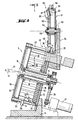
- a cuvette bunker 1 which disordered cuvettes in the form of a loose bed of e.g. Can hold 3000 cuvettes.
- An inclined conveyor belt 2 which is arranged at the bottom of a trough formed by side walls 4 and serves continuously or intermittently, depending on the required cell volume, serves as the transport organ for the metered transfer of the disordered cells from the cell bunker 1 into a feed hopper 3 of a device 5 for separating cells , is drivable.
- the device 5 for separating cuvettes is preferably an alignment and separating device in which the aleatorically supplied, disordered cuvettes are transferred into a single possible position and the aligned cuvettes are separated from the disordered cuvettes.
- the cuvettes, which are oriented in the correct position, are and separating device 5 discharged and placed in a cuvette storage 6.
- a single cuvette e.g. by means of a gripper 8 of a cuvette lift 7, via a transfer device 9 into a work plane of a work station 11, which is indicated only schematically as a block. If the working level is approximately in the access level of the cuvette 25 at the exit of the cuvette storage 6, a cuvette lift is not necessary. In this case, it is sufficient to provide a suitable gripper for transporting the cuvette to the work station.
- FIGS. 2 to 6 An alignment and separating device 5 is shown in FIGS. 2 to 6 in a function-explanatory manner, construction elements that are not relevant for understanding being not shown for the sake of clarity.
- the alignment and separating device 5 essentially consists of a stator 12 and a rotor 13.
- the stator 12 has a bearing block 14 with a stator plate 15 arranged thereon, which is inclined at an angle ⁇ with respect to a vertical straight line.
- the stator plate 15 forms the end of the rotor 13.
- the rotor 13 is rotatably supported by a ball bearing 16 on a bearing disk 17 which is rigidly connected to the bearing block 14 via a centrally arranged bearing tube 18, spaced apart from the stator plate 15.
- the bearing tube 18 is arranged perpendicular to the stator plate 15 and the bearing disk 17. The bearing disc is therefore arranged parallel to the stator plate 15.
- the bearing disk 17 forms, together with a rotatable disk 19, the front end of the rotor 13 opposite the stator plate 15.
- the cylindrical outer casing of the rotor 13 is preferably provided with rods 22 projecting vertically from the disk 19 parallel to the rotor axis of rotation 21 in the direction of the stator plate 15 Round cross-sectional shape, the rod diameter and the angular spacing of the rods 22 are matched to one another on their common pitch circle in such a way that spaces 23 of a defined width b (FIG. 4) result, which are aligned parallel to the axis of rotation 21.
- each of the rods 22 is fixed to the disc 19.
- the other end of each of the rods 22 is free and is spaced from the stator plate 15 by a gap.
- the rods 22 are directed parallel to the bearing tube 18 and inclined by an angle ⁇ with respect to a horizontal straight line 32.
- cuvettes 25 can be poured into the interior of the cage-like rotor 13 in a pouring manner (FIGS. 1, 3).
- the rotor 13 is connected to the drive motor 27 by means of a belt 26 which acts peripherally on the disk 19 (FIG. 1). During operation, the rotor is driven continuously and at a constant rotational speed.
- the speed of rotation of the rotor is preferably between 8 and 15 revolutions per minute. A rotational speed of approximately 11 revolutions per minute is preferred.
- the need to align the cuvettes 25 used here is due to the asymmetry with respect to the x and y axes (FIG. 4).
- this asymmetry is advantageously used for aligning the cuvettes 25.
- Such a cuvette 25 has in the opening-side edge region two diametrically opposite flange lugs 28 which facilitate the transport of the cuvette 25 and whose span a in the y direction exceeds the dimension b of the cuvette tube 29 in the y direction.
- the dimension c of the cuvette tube 29 in the x direction is the same as the dimension of the flange extensions 28 in the x direction.
- the dimension b of the cuvette tube 29 is smaller than c.
- the clear distance d between two adjacent bars 22 is slightly larger than the dimension b, but significantly smaller than the dimension c.
- the cuvette tube 29 can only pass between two rods 22 with its x-axis parallel to the rotor axis of rotation 21.
- the flange lugs 28 are supported on the top of the rods 22, thereby preventing the cuvettes 25 from falling out of the cage-like rotor interior 31.
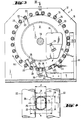
- Fig. 3 it can be seen that the feed opening 24 in the stator plate 15 is offset relative to the axis of rotation 21 of the rotor 13 such that the cuvettes 25 to be brought into the rotor interior 31, in view of the rotational movement (arrow Pf1) and the resulting vertical Change in the position of the rods 22, in the initially falling area.
- the cuvettes 25 By rotating the rotor drum 13 (Pf 1), the cuvettes 25 reach the deepest area of the rotor drum 13, with some cuvettes 25 being able to move their tubes in the correct position between the rods 22 under the action of gravity.
- the cuvettes 25 which have not yet been aligned are then taken into the ascending region of the rotor drum 13, which leads to the agitation caused by gravity and ultimately to the alignment of the cuvette 25 (FIG. 3).
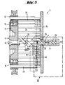
- the rotor axis of rotation 21 is inclined by an angle ⁇ relative to the horizontal 32 such that aligned cuvettes 25 can slide under the action of gravity in the direction of the stator plate 15 until the cuvettes 25 come into contact with the stator plate 15 (FIG. 2).
- the angle of inclination ⁇ is preferably between 10 and 20 degrees. An angle of 15 degrees is preferred.
- the guide disk 33 has a passage in the middle for the bearing tube 18 and also an opening, not shown in the drawings, which coincides with the feed opening 24 of the stator plate 15.
- the guide disc 33 is preferably made of polyoxymethylene (POM). As can be seen from FIG. 3, the distance between the edge of the guide disk 33 and the rods 22 is just slightly larger than the thickness of the flange attachments of the cuvettes.
- the outer peripheral edge 34 is able to support the aligned cuvettes 25 held in the upper region against the force of gravity, so that these cuvettes 25 remain in their position between the rods 22.
- the axial extent of the peripheral edge 34 is selected such that only one cuvette 25 is guided or supported. If, for example, two cuvettes 25 aligned one behind the other are present in a space 23 between two rods 22, only the cuvette 25 near the stator plate is held in position. The second cuvette 25 falls back into the lower region of the rotor 13 due to the action of gravity and loss of alignment.
- Flattenings 35 on the ends of the rods 22 on the stator plate side can improve the support of the cuvette flanges 28.
- the rotor should have the lowest possible mass.
- the bars 22 are preferably made of a light metal, e.g. made of aluminium.
- these are preferably provided with a suitable coating.
- aluminum rods 22 e.g. provided with a nickel teflon coating (e.g. 30% nickel and 70% teflon).
- a cuvette bearing 6 is arranged in the extension of the window opening 36.
- the guidance of the cuvettes 25 is formed by narrow vertical strips 38, on the upper surface 39 of which the cuvette flanges 28 slide with their underside.
- the cuvette tube is guided through the inner surfaces 41 (distance d) of the strips 38.
- a stop 42 is provided, on each of which a cuvette 25 comes into contact in the correct position in an access level of a gripper 8, for example a cuvette lift 7 (FIG. 6).
- the position of the cuvette 25 in the access plane is, by design, spaced apart from the separated cuvette 25 in the cuvette supply (within the rotor) (distance z in FIG. 6). Due to the smaller width e of the strips 38 compared to the flange span a, the gripping member 8 can grip the flange ends, for example.
- the leaf spring 43 which acts on a separated cuvette 25 of the cuvette supply in the rotor interior, aligns the cuvette with the window 36, and on a row of cuvettes bridging the distance z which is already in the cuvette storage 6 (Force v in Figures 5 and 6), the next cuvette can be positioned in the access level of the gripper (Fig. 2, 5, 6).
- the cuvettes 25 bridging the distance z in the cuvette bearing 6 are secured on the upper side by a leaf spring 44 which is fastened to the stator plate 15 (FIG. 2).
- one of the separated cuvettes 25 in the cuvette supply must be separated from the unordered, i.e. not yet aligned cuvettes within the drum (31) or the rotor 13 delimiting partition 45 which extends in the area of the feed opening 24 of the stator plate 15 in an angular range of approximately 90 ° (FIG. 3).
- the partition 45 is fixed to the stator base and has a contour 46 which is adapted to the rotor outer diameter.
- the partition wall 45 is able to keep away from the leaf spring zone on any cuvettes 25 which penetrate through the spaces 23 of the rods 22.
- the leaf spring 43 is attached to the partition 45.
- the rotor is driven continuously, regardless of the amount of cuvette needed. Is used e.g. one cuvette every 6 seconds.
- the individual cuvettes 25 leave the rotor interior 31 of the aligning and separating device 5 through an outlet 36, which is located on the lower part of a guide disk 33 lies.
- the cuvettes 25 delivered at this exit 36 are transported further by transport means which contain the following components: a cuvette storage 6, a gripper 8, and a transfer device 9.
- FIGS. 7 to 13 A preferred variant of the device according to the invention is described below with reference to FIGS. 7 to 13.
- the above-mentioned means of transport are replaced by a swivel wheel 51 and the outlet 36 of the aligning and separating device 5 is not on the lower but on the upper part of the guide disk 33.
- the swivel wheel 51 is rotatably supported by means of ball bearings 52 on a pin 53 which is held on the stator plate 15 by means of a cantilever 54 (FIG. 8).
- the swivel wheel 51 is essentially plate-shaped and has on its radially outer edge teeth 55 directed towards the free ends of the rods 22, the division of which is the same as the division of the rods 22.
- the outer jacket contour 56 of the teeth 55 is designed such that it represents an extension of the cuvette guide formed by the rods 22 in the transfer area (window 36).
- the teeth 55 are provided with recesses 57 which are open at the end and radially on the outside and into which pins 58 projecting from the free ends of the rods 22 can engage in the manner of a gear transmission.
- the swivel wheel 51 is thus rotationally coupled to the rotor 13 such that the spaces 23 in the transfer area (36) are aligned with the spaces 59 between two adjacent teeth 55 of the swivel wheel 51.
- the free end faces of the toothing 55 are covered except for the infeed or outfeed point 61, 62 by a fixed plate 63, whereby the cuvettes 25 located in the swivel wheel 51 are secured against axial falling out.
- the plate 63 is guided in a pot-like manner around the outer peripheral edge of the swivel wheel 51, as a result of which the cuvettes 25 can be supported on the inner peripheral wall 64 and are secured against radial falling out (FIG. 11).
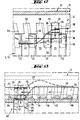
- a sluice spring 66 pushes the cuvettes 25 transported by the alignment and separating device 5 into the transfer area (36) into the lower area of the swivel wheel 51, into the space 59 between two adjacent teeth 55 (FIG. 12).
- the cuvettes 25 are discharged by means of a discharge spring 67 and pushed into a cuvette bearing 65 (FIG. 13). From there, the cuvettes 25 are transported to their destination in the analysis device.
Landscapes
- Physics & Mathematics (AREA)
- Health & Medical Sciences (AREA)
- Life Sciences & Earth Sciences (AREA)
- Chemical & Material Sciences (AREA)
- Analytical Chemistry (AREA)
- Biochemistry (AREA)
- General Health & Medical Sciences (AREA)
- General Physics & Mathematics (AREA)
- Immunology (AREA)
- Pathology (AREA)
- Automatic Analysis And Handling Materials Therefor (AREA)
- Optical Measuring Cells (AREA)
- Specific Conveyance Elements (AREA)
- Sorting Of Articles (AREA)
Claims (7)
- Dispositif pour distribuer individuellement des cuvettes qui sont fournies à un appareil d'analyse sous la forme d'un produit en vrac, où les cuvettes sont propres à exécuter des mesures photométriques des échantillons contenus dans les cuvettes et où chaque cuvette a un corps de forme tubulaire doté d'un rebord à collerette qui s'étend vers l'extérieur et qui est perpendiculaire à la paroi de la cuvette, lequel dispositif comprend les éléments suivants :a) un emplacement de réception (1) pour recevoir des cuvettes (25) sous la forme d'un produit en vrac,b) un dispositif (5) pour distribuer individuellement des cuvettes, lequel dispositif est doté d'une entrée (24) à travers laquelle des cuvettes en vrac sont fournies au dispositif (5) et d'une sortie (36) à travers laquelle des cuvettes individuelles sortent du dispositif l'une derrière l'autre, etc) un moyen (2) pour le transport des cuvettes (25) en vrac depuis l'emplacement de réception (1) jusqu'à l'entrée (24) du dispositif (5) pour la distribution individuelle des cuvettes,lequel dispositif est caractérisé en ce qu'il est propre à distribuer individuellement des cuvettes qui sont fabriquées dans une matière plastique transparente, se composant d'une seule pièce de forme et ayant deux parois à faces parallèles, en ce que les rebords à collerette des deux parois à faces parallèles sont symétriques l'un de l'autre par rapport à l'axe longitudinal de la cuvette et où le dispositif (5) pour la distribution individuelle des cuvettes (25) en vrac comprend:d) une plaque fixe (15) qui est montée sur un socle (14) et qui est inclinée par rapport à une ligne verticale,e) un tube-support (18) qui est monté sur la plaque fixe (15) et qui est perpendiculaire à celle-ci,f) un disque rotatif (19) qui est logé de façon pivotante sur le tube-support (18) et qui est parallèle à la plaque fixe (15),g) un ensemble cylindrique, fixé sur le disque rotatif (19), de barres cylindriques (22) de mêmes dimensions, qui sont disposées en étant espacées les unes des autres avec un même intervalle, le long d'un cercle qui est concentrique avec le tube-support (18), où les barres (22) sont parallèles au tube-support (18) et, comme celui-ci, sont inclinées suivant un angle (α) par rapport à une ligne horizontale, et où une extrémité de chacune des barres (22) est solidement accouplée au disque rotatif (19), tandis que l'autre extrémité de la barre est libre et est séparée de la plaque fixe par un espace, et où l'intervalle entre des barres voisines (22) est d'une dimension telle que le corps d'une cuvette peut passer entre les barres (22) lorsque les parois à faces parallèles de la cuvette sont parallèles à l'axe longitudinal des barres (22),h) des moyens (26, 27) entraînés par un moteur faisant tourner le disque rotatif (19) à vitesse constante,i) un disque fixe (33) de forme annulaire qui est monté sur la plaque fixe (15), lequel disque présente en son milieu un passage pour le tube-support (18) et dont le bord circonférentiel se trouve à l'intérieur de l'ensemble cylindrique de barres (22), où l'intervalle entre le bord du disque fixe (33) de forme annulaire et les barres (22) est à peine supérieur à l'épaisseur des rebords à collerette des cuvettes (25), etj) une première ouverture (24) pratiquée dans la plaque fixe (15), ladite ouverture se trouvant au-dessus du bord inférieur du disque fixe (33) de forme annulaire et servant d'entrée pour introduire les cuvettes (25) en vrac dans la structure en forme de cage qui est formée par la plaque fixe (15), par l'ensemble de barres (22) et par le disque rotatif (19).
- Dispositif selon la revendication 1, caractérisé en ce que le dispositif (5) pour la distribution individuelle de cuvettes (25) en vrac comprend en outre les éléments suivants :k) une seconde ouverture (36) pratiquée dans la plaque fixe (15), ladite ouverture se trouvant sur le bord inférieur du disque fixe (33) de forme annulaire et servant de sortie pour fournir les cuvettes (25) individuelles dont les rebords à collerette, lors de la rotation de la structure en forme de cage, viennent se placer entre le bord circonférentiel du disque fixe (33) de forme annulaire et l'ensemble de barres (22), etl) des moyens (43) pour faire sortir les cuvettes individuelles (25) par la seconde ouverture pratiquée dans la plaque fixe (15) lorsque les cuvettes se trouvent directement devant la seconde ouverture pendant la rotation de la structure en forme de cage.
- Dispositif selon la revendication 1, caractérisé en ce que le dispositif (5) pour la distribution individuelle de cuvettes (25) en vrac comprend en outre les éléments suivants :k) une seconde ouverture (36) pratiquée dans la plaque fixe (15), ladite ouverture se trouvant sur le bord supérieur du disque fixe (33) de forme annulaire et servant de sortie pour fournir les cuvettes (25) individuelles dont les rebords à collerette, lors de la rotation de la structure en forme de cage, viennent se placer entre le bord circonférentiel du disque fixe (33) de forme annulaire et l'ensemble de barres (22), etl) des moyens (43) pour faire sortir les cuvettes individuelles (25) par la seconde ouverture pratiquée dans la plaque fixe (15) lorsque les cuvettes se trouvent directement devant la seconde ouverture pendant la rotation de la structure en forme de cage.
- Dispositif selon la revendication 2 ou 3, caractérisé en ce que l'angle d'inclinaison des barres (22), par rapport à une ligne horizontale (32), est égal à une plage comprise entre 10 et 20 degrés.
- Dispositif selon la revendication 2 ou 3, caractérisé en ce que l'angle d'inclinaison des barres (22), par rapport à une ligne horizontale (32), est égal à 15 degrés environ.
- Dispositif selon la revendication 2 ou 3, caractérisé en ce que les moyens (26, 27) entraînés par un moteur pour faire tourner le disque rotatif (19) ont une vitesse de rotation comprise entre 8 et 15 tours par minute.
- Dispositif selon la revendication 2 ou 3, caractérisé en ce que les moyens (26, 27) entraînés par un moteur pour faire tourner le disque rotatif (19) ont une vitesse de rotation d'environ 11 tours par minute.
Applications Claiming Priority (2)
| Application Number | Priority Date | Filing Date | Title |
|---|---|---|---|
| CH139192 | 1992-04-30 | ||
| CH1391/92 | 1992-04-30 |
Publications (2)
| Publication Number | Publication Date |
|---|---|
| EP0567893A1 EP0567893A1 (fr) | 1993-11-03 |
| EP0567893B1 true EP0567893B1 (fr) | 1997-07-02 |
Family
ID=4209335
Family Applications (1)
| Application Number | Title | Priority Date | Filing Date |
|---|---|---|---|
| EP93106346A Expired - Lifetime EP0567893B1 (fr) | 1992-04-30 | 1993-04-20 | Dispositif pour distribuer individuellement des cuvettes à un appareil d'analyse automatique |
Country Status (8)
| Country | Link |
|---|---|
| US (1) | US5333717A (fr) |
| EP (1) | EP0567893B1 (fr) |
| JP (1) | JP2525542B2 (fr) |
| CA (1) | CA2093509C (fr) |
| DE (1) | DE59306829D1 (fr) |
| DK (1) | DK0567893T3 (fr) |
| ES (1) | ES2106217T3 (fr) |
| GR (1) | GR3024892T3 (fr) |
Cited By (1)
| Publication number | Priority date | Publication date | Assignee | Title |
|---|---|---|---|---|
| EP2860137A1 (fr) | 2013-10-10 | 2015-04-15 | F.Hoffmann-La Roche Ag | Appareil pour séparer des cuvettes |
Families Citing this family (13)
| Publication number | Priority date | Publication date | Assignee | Title |
|---|---|---|---|---|
| JP2970489B2 (ja) * | 1995-09-11 | 1999-11-02 | 住友電装株式会社 | アダプター供給装置 |
| FR2804511A1 (fr) * | 2000-01-28 | 2001-08-03 | Biomerieux Sa | Dispositif d'alimentation en cuvettes d'un appareil d'analyse biologique et procede d'alimentation d'un tel appareil |
| EP1136825A1 (fr) * | 2000-03-13 | 2001-09-26 | Biopsytec S.A.R.L. | Dispositif pour le triage, l'enregistrement et le stockage automatisés des récipients de réaction |
| US7731899B2 (en) | 2007-02-08 | 2010-06-08 | Biokit, S.A. | Apparatus and methods for dispensing sample holders |
| EP2883667B1 (fr) | 2013-12-10 | 2020-01-15 | F.Hoffmann-La Roche Ag | Dispositif et procédé permettant de saisir des récipients |
| ES2895944T3 (es) | 2014-12-13 | 2022-02-23 | Hoffmann La Roche | Dispositivo para almacenar recipientes de fluidos |
| JP6549960B2 (ja) * | 2015-10-07 | 2019-07-24 | 日本電子株式会社 | 容器供給ユニット及び自動分析装置 |
| FR3046998A1 (fr) * | 2016-01-26 | 2017-07-28 | Gebo Packaging Solutions France | Dispositif et methode de convoyage controle |
| CN108097133B (zh) * | 2017-12-14 | 2020-03-31 | 迪瑞医疗科技股份有限公司 | 试剂混匀机构及其混匀方法 |
| WO2019164904A1 (fr) * | 2018-02-23 | 2019-08-29 | Siemens Healthcare Diagnostics Inc. | Analyseurs cliniques et procédés de transport de cuvettes |
| CN110567505A (zh) * | 2019-09-25 | 2019-12-13 | 王艺锦 | 一种应用于智能制造的自动抽检机构 |
| CN110876514A (zh) * | 2019-11-14 | 2020-03-13 | 朱梁 | 一种拉链装配机 |
| CN113820506A (zh) * | 2021-08-10 | 2021-12-21 | 西安金域医学检验所有限公司 | 一种自动排号仪 |
Family Cites Families (11)
| Publication number | Priority date | Publication date | Assignee | Title |
|---|---|---|---|---|
| US2025273A (en) * | 1935-05-27 | 1935-12-24 | Frank H Dellaree | Pick-up device for fasteners |
| US3658207A (en) * | 1970-01-26 | 1972-04-25 | Tangen Drives | Centrifugal feeder for headed parts |
| US3907099A (en) * | 1974-03-13 | 1975-09-23 | Arthur J Smith | Feeder for headed objects |
| DE2532763B1 (de) * | 1975-07-22 | 1976-08-05 | Siemens Ag | Transportvorrichtung mit kodierwerk fuer probengefaesse |
| US4128159A (en) * | 1977-12-22 | 1978-12-05 | Pataki William V | Apparatus for feeding and orienting parts |
| US4312438A (en) * | 1978-03-27 | 1982-01-26 | Vatsvog Marlo K | Bullet alignment apparatus |
| US4238023A (en) * | 1979-05-29 | 1980-12-09 | Promatic International Limited | Apparatus for orienting hollow, cap-like articles |
| US4306649A (en) * | 1980-04-07 | 1981-12-22 | Brown International Corporation | Rotary feeder mechanism for fruit juice extracting apparatus |
| US4610345A (en) * | 1980-12-03 | 1986-09-09 | Pmc Industries | Method and apparatus for orienting and delivering dispenser cap assemblies |
| US4453626A (en) * | 1980-12-29 | 1984-06-12 | The Arthur G. Russell Company, Incorporated | Vibratory feeding apparatus |
| JPH0275520A (ja) * | 1988-09-09 | 1990-03-15 | Nitto Seiko Co Ltd | 有頭部品の検査装置 |
-
1993
- 1993-04-06 CA CA002093509A patent/CA2093509C/fr not_active Expired - Fee Related
- 1993-04-19 US US08/049,754 patent/US5333717A/en not_active Expired - Lifetime
- 1993-04-20 DK DK93106346.5T patent/DK0567893T3/da not_active Application Discontinuation
- 1993-04-20 ES ES93106346T patent/ES2106217T3/es not_active Expired - Lifetime
- 1993-04-20 DE DE59306829T patent/DE59306829D1/de not_active Expired - Fee Related
- 1993-04-20 EP EP93106346A patent/EP0567893B1/fr not_active Expired - Lifetime
- 1993-04-28 JP JP5101641A patent/JP2525542B2/ja not_active Expired - Fee Related
-
1997
- 1997-09-30 GR GR970402539T patent/GR3024892T3/el unknown
Cited By (1)
| Publication number | Priority date | Publication date | Assignee | Title |
|---|---|---|---|---|
| EP2860137A1 (fr) | 2013-10-10 | 2015-04-15 | F.Hoffmann-La Roche Ag | Appareil pour séparer des cuvettes |
Also Published As
| Publication number | Publication date |
|---|---|
| DK0567893T3 (da) | 1998-02-02 |
| JP2525542B2 (ja) | 1996-08-21 |
| JPH0666816A (ja) | 1994-03-11 |
| DE59306829D1 (de) | 1997-08-07 |
| ES2106217T3 (es) | 1997-11-01 |
| US5333717A (en) | 1994-08-02 |
| EP0567893A1 (fr) | 1993-11-03 |
| CA2093509A1 (fr) | 1993-10-31 |
| CA2093509C (fr) | 1997-04-29 |
| GR3024892T3 (en) | 1998-01-30 |
Similar Documents
| Publication | Publication Date | Title |
|---|---|---|
| EP0567893A1 (fr) | Dispositif pour distribuer individuellement des cuvettes à un appareil d'analyse automatique | |
| DE68918962T2 (de) | Verfahren und Vorrichtung zum Durchführen von Analysen mit Mengmöglichkeit. | |
| DE69534651T2 (de) | Verfahren und vorrichtung zur automatischen chemischen analyse | |
| CH625346A5 (fr) | ||
| DE3883648T2 (de) | Misch- und Dosierapparat, z.B. Futterbehälter. | |
| DE102021101384B3 (de) | System zum Transport von sterilen schüttfähigen Verschlusselementen | |
| EP0431455A2 (fr) | Dispositif d'évaluation de bandes à essais multiples | |
| DE2262556A1 (de) | Vorrichtung zur pruefung von ampullen | |
| EP0358878B1 (fr) | Dispositif doseur pour une machine à distribuer | |
| EP0099980B1 (fr) | Dispositif pour la formation de portions de tabac | |
| DE19520191A1 (de) | Verfahren zur On-Line-Gewichtskontrolle von Kapseln | |
| DE3030508C2 (fr) | ||
| EP0045839A1 (fr) | Dispositif de dosage pour matériau en vrac sous forme de poussière ou de poudre ou capable de s'écouler | |
| EP0534942A1 (fr) | Etoile de triage pour machines de traitement de recipients. | |
| DE2335533A1 (de) | Analysenapparat | |
| EP0223088A2 (fr) | Balance combinatoire | |
| DE69527411T2 (de) | Vorrichtung zum Durchleuchten von Eiern auf Anwesenheit von Blut | |
| DE2316355C2 (de) | Vorrichtung zum Ausrichten von gleichförmigen langgestreckten Gegenständen, insbesondere rohrförmigen Gehäusen für Schreibgeräte | |
| EP0168414B1 (fr) | Dispositif de distribution pour container de materiau pulverulent | |
| EP0756572B1 (fr) | Dispositif de prelevement dose de solides en vrac | |
| DE2219369A1 (de) | Einrichtung zur automatischen Durchführung chemischer Analysen | |
| DE3417498A1 (de) | Speichereinrichtung fuer integrierte schaltkreise | |
| DE2559162C3 (de) | Anlage zur Kompostierung von Müll und/oder eingedicktem Schlamm | |
| DE1291185B (de) | Maschine zum Mischen und Foerdern von Schuettgut | |
| DE4039678C2 (fr) |
Legal Events
| Date | Code | Title | Description |
|---|---|---|---|
| PUAI | Public reference made under article 153(3) epc to a published international application that has entered the european phase |
Free format text: ORIGINAL CODE: 0009012 |
|
| 17P | Request for examination filed |
Effective date: 19930420 |
|
| AK | Designated contracting states |
Kind code of ref document: A1 Designated state(s): BE CH DE DK ES FR GB GR IE IT LI LU NL PT |
|
| GRAG | Despatch of communication of intention to grant |
Free format text: ORIGINAL CODE: EPIDOS AGRA |
|
| 17Q | First examination report despatched |
Effective date: 19960726 |
|
| GRAH | Despatch of communication of intention to grant a patent |
Free format text: ORIGINAL CODE: EPIDOS IGRA |
|
| GRAH | Despatch of communication of intention to grant a patent |
Free format text: ORIGINAL CODE: EPIDOS IGRA |
|
| GRAA | (expected) grant |
Free format text: ORIGINAL CODE: 0009210 |
|
| AK | Designated contracting states |
Kind code of ref document: B1 Designated state(s): BE CH DE DK ES FR GB GR IE IT LI LU NL PT |
|
| REG | Reference to a national code |
Ref country code: CH Ref legal event code: EP |
|
| REF | Corresponds to: |
Ref document number: 59306829 Country of ref document: DE Date of ref document: 19970807 |
|
| ET | Fr: translation filed | ||
| GBT | Gb: translation of ep patent filed (gb section 77(6)(a)/1977) |
Effective date: 19970924 |
|
| REG | Reference to a national code |
Ref country code: PT Ref legal event code: SC4A Free format text: AVAILABILITY OF NATIONAL TRANSLATION Effective date: 19970718 |
|
| REG | Reference to a national code |
Ref country code: ES Ref legal event code: FG2A Ref document number: 2106217 Country of ref document: ES Kind code of ref document: T3 |
|
| REG | Reference to a national code |
Ref country code: GR Ref legal event code: FG4A Free format text: 3024892 |
|
| REG | Reference to a national code |
Ref country code: DK Ref legal event code: T3 |
|
| PGFP | Annual fee paid to national office [announced via postgrant information from national office to epo] |
Ref country code: PT Payment date: 19980408 Year of fee payment: 6 |
|
| PGFP | Annual fee paid to national office [announced via postgrant information from national office to epo] |
Ref country code: GB Payment date: 19980414 Year of fee payment: 6 |
|
| PGFP | Annual fee paid to national office [announced via postgrant information from national office to epo] |
Ref country code: DK Payment date: 19980417 Year of fee payment: 6 |
|
| PGFP | Annual fee paid to national office [announced via postgrant information from national office to epo] |
Ref country code: NL Payment date: 19980428 Year of fee payment: 6 Ref country code: ES Payment date: 19980428 Year of fee payment: 6 |
|
| PGFP | Annual fee paid to national office [announced via postgrant information from national office to epo] |
Ref country code: IE Payment date: 19980429 Year of fee payment: 6 |
|
| PGFP | Annual fee paid to national office [announced via postgrant information from national office to epo] |
Ref country code: GR Payment date: 19980430 Year of fee payment: 6 |
|
| PGFP | Annual fee paid to national office [announced via postgrant information from national office to epo] |
Ref country code: LU Payment date: 19980504 Year of fee payment: 6 |
|
| PGFP | Annual fee paid to national office [announced via postgrant information from national office to epo] |
Ref country code: CH Payment date: 19980507 Year of fee payment: 6 |
|
| PLBE | No opposition filed within time limit |
Free format text: ORIGINAL CODE: 0009261 |
|
| PGFP | Annual fee paid to national office [announced via postgrant information from national office to epo] |
Ref country code: BE Payment date: 19980609 Year of fee payment: 6 |
|
| 26N | No opposition filed | ||
| PG25 | Lapsed in a contracting state [announced via postgrant information from national office to epo] |
Ref country code: LU Free format text: LAPSE BECAUSE OF NON-PAYMENT OF DUE FEES Effective date: 19990420 Ref country code: IE Free format text: LAPSE BECAUSE OF NON-PAYMENT OF DUE FEES Effective date: 19990420 Ref country code: GB Free format text: LAPSE BECAUSE OF NON-PAYMENT OF DUE FEES Effective date: 19990420 |
|
| PG25 | Lapsed in a contracting state [announced via postgrant information from national office to epo] |
Ref country code: ES Free format text: LAPSE BECAUSE OF NON-PAYMENT OF DUE FEES Effective date: 19990421 |
|
| PG25 | Lapsed in a contracting state [announced via postgrant information from national office to epo] |
Ref country code: LI Free format text: LAPSE BECAUSE OF NON-PAYMENT OF DUE FEES Effective date: 19990430 Ref country code: GR Free format text: LAPSE BECAUSE OF NON-PAYMENT OF DUE FEES Effective date: 19990430 Ref country code: DK Free format text: LAPSE BECAUSE OF NON-PAYMENT OF DUE FEES Effective date: 19990430 Ref country code: CH Free format text: LAPSE BECAUSE OF NON-PAYMENT OF DUE FEES Effective date: 19990430 Ref country code: BE Free format text: LAPSE BECAUSE OF NON-PAYMENT OF DUE FEES Effective date: 19990430 |
|
| BERE | Be: lapsed |
Owner name: F. HOFFMANN-LA ROCHE A.G. Effective date: 19990430 |
|
| PG25 | Lapsed in a contracting state [announced via postgrant information from national office to epo] |
Ref country code: PT Free format text: LAPSE BECAUSE OF NON-PAYMENT OF DUE FEES Effective date: 19991031 |
|
| PG25 | Lapsed in a contracting state [announced via postgrant information from national office to epo] |
Ref country code: NL Free format text: LAPSE BECAUSE OF NON-PAYMENT OF DUE FEES Effective date: 19991101 |
|
| GBPC | Gb: european patent ceased through non-payment of renewal fee |
Effective date: 19990420 |
|
| REG | Reference to a national code |
Ref country code: CH Ref legal event code: PL |
|
| NLV4 | Nl: lapsed or anulled due to non-payment of the annual fee |
Effective date: 19991101 |
|
| REG | Reference to a national code |
Ref country code: IE Ref legal event code: MM4A |
|
| REG | Reference to a national code |
Ref country code: PT Ref legal event code: MM4A Free format text: LAPSE DUE TO NON-PAYMENT OF FEES Effective date: 19991031 |
|
| REG | Reference to a national code |
Ref country code: DK Ref legal event code: EBP |
|
| REG | Reference to a national code |
Ref country code: ES Ref legal event code: FD2A Effective date: 20010503 |
|
| PGFP | Annual fee paid to national office [announced via postgrant information from national office to epo] |
Ref country code: FR Payment date: 20060403 Year of fee payment: 14 |
|
| PGFP | Annual fee paid to national office [announced via postgrant information from national office to epo] |
Ref country code: DE Payment date: 20060428 Year of fee payment: 14 |
|
| PGFP | Annual fee paid to national office [announced via postgrant information from national office to epo] |
Ref country code: IT Payment date: 20060430 Year of fee payment: 14 |
|
| PG25 | Lapsed in a contracting state [announced via postgrant information from national office to epo] |
Ref country code: DE Free format text: LAPSE BECAUSE OF NON-PAYMENT OF DUE FEES Effective date: 20071101 |
|
| PG25 | Lapsed in a contracting state [announced via postgrant information from national office to epo] |
Ref country code: FR Free format text: LAPSE BECAUSE OF NON-PAYMENT OF DUE FEES Effective date: 20070430 |
|
| PG25 | Lapsed in a contracting state [announced via postgrant information from national office to epo] |
Ref country code: IT Free format text: LAPSE BECAUSE OF NON-PAYMENT OF DUE FEES Effective date: 20070420 |