EP0568067A1 - Système d'identification de radiofréquence avec charge contrôlée - Google Patents
Système d'identification de radiofréquence avec charge contrôlée Download PDFInfo
- Publication number
- EP0568067A1 EP0568067A1 EP93106974A EP93106974A EP0568067A1 EP 0568067 A1 EP0568067 A1 EP 0568067A1 EP 93106974 A EP93106974 A EP 93106974A EP 93106974 A EP93106974 A EP 93106974A EP 0568067 A1 EP0568067 A1 EP 0568067A1
- Authority
- EP
- European Patent Office
- Prior art keywords
- interrogation
- signal
- duration
- pulse
- transponder
- Prior art date
- Legal status (The legal status is an assumption and is not a legal conclusion. Google has not performed a legal analysis and makes no representation as to the accuracy of the status listed.)
- Granted
Links
Images


Classifications
-
- G—PHYSICS
- G06—COMPUTING OR CALCULATING; COUNTING
- G06K—GRAPHICAL DATA READING; PRESENTATION OF DATA; RECORD CARRIERS; HANDLING RECORD CARRIERS
- G06K19/00—Record carriers for use with machines and with at least a part designed to carry digital markings
- G06K19/06—Record carriers for use with machines and with at least a part designed to carry digital markings characterised by the kind of the digital marking, e.g. shape, nature, code
- G06K19/067—Record carriers with conductive marks, printed circuits or semiconductor circuit elements, e.g. credit or identity cards also with resonating or responding marks without active components
- G06K19/07—Record carriers with conductive marks, printed circuits or semiconductor circuit elements, e.g. credit or identity cards also with resonating or responding marks without active components with integrated circuit chips
- G06K19/0701—Record carriers with conductive marks, printed circuits or semiconductor circuit elements, e.g. credit or identity cards also with resonating or responding marks without active components with integrated circuit chips at least one of the integrated circuit chips comprising an arrangement for power management
- G06K19/0712—Record carriers with conductive marks, printed circuits or semiconductor circuit elements, e.g. credit or identity cards also with resonating or responding marks without active components with integrated circuit chips at least one of the integrated circuit chips comprising an arrangement for power management the arrangement being capable of triggering distinct operating modes or functions dependent on the strength of an energy or interrogation field in the proximity of the record carrier
-
- H—ELECTRICITY
- H04—ELECTRIC COMMUNICATION TECHNIQUE
- H04B—TRANSMISSION
- H04B7/00—Radio transmission systems, i.e. using radiation field
-
- G—PHYSICS
- G01—MEASURING; TESTING
- G01S—RADIO DIRECTION-FINDING; RADIO NAVIGATION; DETERMINING DISTANCE OR VELOCITY BY USE OF RADIO WAVES; LOCATING OR PRESENCE-DETECTING BY USE OF THE REFLECTION OR RERADIATION OF RADIO WAVES; ANALOGOUS ARRANGEMENTS USING OTHER WAVES
- G01S13/00—Systems using the reflection or reradiation of radio waves, e.g. radar systems; Analogous systems using reflection or reradiation of waves whose nature or wavelength is irrelevant or unspecified
- G01S13/74—Systems using reradiation of radio waves, e.g. secondary radar systems; Analogous systems
- G01S13/75—Systems using reradiation of radio waves, e.g. secondary radar systems; Analogous systems using transponders powered from received waves, e.g. using passive transponders, or using passive reflectors
- G01S13/751—Systems using reradiation of radio waves, e.g. secondary radar systems; Analogous systems using transponders powered from received waves, e.g. using passive transponders, or using passive reflectors wherein the responder or reflector radiates a coded signal
- G01S13/758—Systems using reradiation of radio waves, e.g. secondary radar systems; Analogous systems using transponders powered from received waves, e.g. using passive transponders, or using passive reflectors wherein the responder or reflector radiates a coded signal using a signal generator powered by the interrogation signal
-
- G—PHYSICS
- G06—COMPUTING OR CALCULATING; COUNTING
- G06K—GRAPHICAL DATA READING; PRESENTATION OF DATA; RECORD CARRIERS; HANDLING RECORD CARRIERS
- G06K19/00—Record carriers for use with machines and with at least a part designed to carry digital markings
- G06K19/06—Record carriers for use with machines and with at least a part designed to carry digital markings characterised by the kind of the digital marking, e.g. shape, nature, code
- G06K19/067—Record carriers with conductive marks, printed circuits or semiconductor circuit elements, e.g. credit or identity cards also with resonating or responding marks without active components
- G06K19/07—Record carriers with conductive marks, printed circuits or semiconductor circuit elements, e.g. credit or identity cards also with resonating or responding marks without active components with integrated circuit chips
- G06K19/0701—Record carriers with conductive marks, printed circuits or semiconductor circuit elements, e.g. credit or identity cards also with resonating or responding marks without active components with integrated circuit chips at least one of the integrated circuit chips comprising an arrangement for power management
- G06K19/0707—Record carriers with conductive marks, printed circuits or semiconductor circuit elements, e.g. credit or identity cards also with resonating or responding marks without active components with integrated circuit chips at least one of the integrated circuit chips comprising an arrangement for power management the arrangement being capable of collecting energy from external energy sources, e.g. thermocouples, vibration, electromagnetic radiation
-
- G—PHYSICS
- G06—COMPUTING OR CALCULATING; COUNTING
- G06K—GRAPHICAL DATA READING; PRESENTATION OF DATA; RECORD CARRIERS; HANDLING RECORD CARRIERS
- G06K7/00—Methods or arrangements for sensing record carriers, e.g. for reading patterns
- G06K7/0008—General problems related to the reading of electronic memory record carriers, independent of its reading method, e.g. power transfer
-
- G—PHYSICS
- G06—COMPUTING OR CALCULATING; COUNTING
- G06K—GRAPHICAL DATA READING; PRESENTATION OF DATA; RECORD CARRIERS; HANDLING RECORD CARRIERS
- G06K7/00—Methods or arrangements for sensing record carriers, e.g. for reading patterns
- G06K7/10—Methods or arrangements for sensing record carriers, e.g. for reading patterns by electromagnetic radiation, e.g. optical sensing; by corpuscular radiation
- G06K7/10009—Methods or arrangements for sensing record carriers, e.g. for reading patterns by electromagnetic radiation, e.g. optical sensing; by corpuscular radiation sensing by radiation using wavelengths larger than 0.1 mm, e.g. radio-waves or microwaves
- G06K7/10019—Methods or arrangements for sensing record carriers, e.g. for reading patterns by electromagnetic radiation, e.g. optical sensing; by corpuscular radiation sensing by radiation using wavelengths larger than 0.1 mm, e.g. radio-waves or microwaves resolving collision on the communication channels between simultaneously or concurrently interrogated record carriers.
- G06K7/10029—Methods or arrangements for sensing record carriers, e.g. for reading patterns by electromagnetic radiation, e.g. optical sensing; by corpuscular radiation sensing by radiation using wavelengths larger than 0.1 mm, e.g. radio-waves or microwaves resolving collision on the communication channels between simultaneously or concurrently interrogated record carriers. the collision being resolved in the time domain, e.g. using binary tree search or RFID responses allocated to a random time slot
- G06K7/10039—Methods or arrangements for sensing record carriers, e.g. for reading patterns by electromagnetic radiation, e.g. optical sensing; by corpuscular radiation sensing by radiation using wavelengths larger than 0.1 mm, e.g. radio-waves or microwaves resolving collision on the communication channels between simultaneously or concurrently interrogated record carriers. the collision being resolved in the time domain, e.g. using binary tree search or RFID responses allocated to a random time slot interrogator driven, i.e. synchronous
-
- G—PHYSICS
- G06—COMPUTING OR CALCULATING; COUNTING
- G06K—GRAPHICAL DATA READING; PRESENTATION OF DATA; RECORD CARRIERS; HANDLING RECORD CARRIERS
- G06K7/00—Methods or arrangements for sensing record carriers, e.g. for reading patterns
- G06K7/10—Methods or arrangements for sensing record carriers, e.g. for reading patterns by electromagnetic radiation, e.g. optical sensing; by corpuscular radiation
- G06K7/10009—Methods or arrangements for sensing record carriers, e.g. for reading patterns by electromagnetic radiation, e.g. optical sensing; by corpuscular radiation sensing by radiation using wavelengths larger than 0.1 mm, e.g. radio-waves or microwaves
- G06K7/10198—Methods or arrangements for sensing record carriers, e.g. for reading patterns by electromagnetic radiation, e.g. optical sensing; by corpuscular radiation sensing by radiation using wavelengths larger than 0.1 mm, e.g. radio-waves or microwaves setting parameters for the interrogator, e.g. programming parameters and operating modes
- G06K7/10217—Methods or arrangements for sensing record carriers, e.g. for reading patterns by electromagnetic radiation, e.g. optical sensing; by corpuscular radiation sensing by radiation using wavelengths larger than 0.1 mm, e.g. radio-waves or microwaves setting parameters for the interrogator, e.g. programming parameters and operating modes parameter settings controlling the transmission power of the interrogator
-
- G—PHYSICS
- G08—SIGNALLING
- G08C—TRANSMISSION SYSTEMS FOR MEASURED VALUES, CONTROL OR SIMILAR SIGNALS
- G08C17/00—Arrangements for transmitting signals characterised by the use of a wireless electrical link
- G08C17/02—Arrangements for transmitting signals characterised by the use of a wireless electrical link using a radio link
Definitions
- This invention relates to radio-frequency identification systems which operate with sequential power/read functions.
- Radio-frequency identification systems with interrogator sequential power/read functions operate over a large dynamic range with regard to field strength levels. This phenomena stems from the fact that the largest required reading range of any given read area defines the power level in conjunction with the predetermined time window. If an RF-ID system is designed for maximum range, the close-proximity field strength is very high for the transponders nearest the interrogator. In such cases, transponders may be heated up by the over-voltage protection circuit which is absorbing excessive power in near field conditions. The second negative effect is that most of the charge-up pulse is wasted for the closest transponders.
- a power pulse must be 50 milliseconds in length to charge the furthest transponder, but the closest transponder requires only .5 milliseconds to obtain sufficient energy to return a reply, the other 49.5 milliseconds of the power pulse is wasted on the closest transponders.
- over-charging problem is especially disadvantageous in temperature sensor applications.
- an accurate temperature measurement may not be obtainable because the transponder eventually dissipates the extra power pulse energy in the surrounding area of the sensor, which is typically in the temperature measurement vicinity.
- Over-charging can cause the temperature of the transponder to rise anywhere from 20-80 C, depending upon the required reading range and/or the transponders distance from the interrogator, thereby causing enormous errors in the temperature measurement readings.
- the duration or the amplitude of the interrogation power pulse thus the energy consumption and heating-up of the transponder, as well as the energy consumption of the interrogation unit can be optimized by the proposed invention.
- the RF_ID system transmits a narrow interrogation pulse, for example of 5 msec duration and then monitors for an even shorter duration, for example 1 msec, for a transponders response signal. The monitoring duration is maintained a minimum to create the most efficient charge-up system.
- the interrogator increases the interrogation pulse duration in steps, until the receiver in the interrogator detects a response signal.
- a response signal indicates that the transponder has received enough power from the interrogation signal, represented as a voltage stored on a capacitor located in the transponder.
- This system can be supported by transponders which have no discharge function, to allow the transponders to achieve the final charge-up voltage level with a series of combined short duration power pulses, or by transponders which have discharge functions and which must wait for an adequate duration interrogation pulse to receive enough voltage.
- the amplitude of the interrogation pulses can be increased to produce a similar increase in the amount of interrogation power transmitted.
- transponder when more than one transponder is within an interrogation read range, after a transponder has sent a response message back to the interrogator, that transponder is inactivated for a predetermined amount of time to allow the rest of the transponders in the read range to respond to an interrogation pulse.
- Figure 1 is a block diagram of the interrogator showing those elements that make up an integral part of the invention.
- FIG. 2 is a block diagram of the transponder showing those elements that make up an integral part of the invention.
- Figure 3 is a timing and voltage diagram showing the excess energy a close transponder must dissipate when a power pulse to reach the farthest power pulse is transmitted by a prior art interrogator.
- Figure 4 is a timing and voltage diagram that shows the absorption of the interrogation pulse by dischargeable transponders according to the invention.
- Figure 5 is a timing and voltage diagram that shows the aborption and the discharge of the interrogation pulse by dischargeable transponders according to the invention.
- Figure 6 is a timing and voltage diagram that shows how transponders with no discharge function can be charged with a series of like duration interrogation pulses.
- Figure 7 is a timing and voltage diagram that shows how transponders with no discharge function can be charged with a series of increasingly longer duration interrogation pulses.
- Figure 8 is a timing and voltage diagram showing the optimum length of time and voltage of the interrogation pulse in a high speed automobile vehicle identification application.
- Figure 9 is a block diagram of the transponder showing those elements that make up a part of another preferred emobodiment according to the invention.
- Figure 10 is a timing and voltage diagram showing the increase in amplitude of the interrogation signal in a preferred embodiment according to the invention.
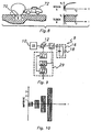
- FIG. 1 A block diagram of an interrogator is shown in Figure 1 .
- an oscillator 10 of the interrogator 9 commanded by a microprocessor not shown, sends a signal through a variable amplifier 12 to a coupler 14 , where the amplified interrogation signal resonates the parallel resonant combination 16 and is transmitted via the antenna 18 .
- the first interrogation signal transmitted is a short power pulse, for example, 5 milliseconds, which is shorter in pulse duration than would be required to power up the most distant transponder.
- the receiver 20 of the interrogator 9 then listens for a short, predetermined time period, for example, 1 millisecond, for a transponders response signal.
- the receiver 20 If the receiver 20 does not detect a response during the predetermined listening time period, it sends a control signal to the Pulse Width Control Circuitry 21 .
- the Pulse Width Control Circuitry 21 includes a data control circuit 22 which receives the control signal from receiver 20 , and in turn sends a signal to the time duration control circuit 24 to increase the duration of the interrogation pulse.
- the interrogator 9 continues a cycle of sending successively longer duration interrogation pulses and monitoring for a transponders response until the receiver 20 in the interrogator 9 detects the presence of a transponders response signal, thereby signifying an adequate charge-up power level in the transponder.
- the amplitude of the interrogation signal could be controlled with a Power Control Circuit 27 which increases the amplitude of the interrogation pulse in successive steps.
- an oscillator 10 of the interrogator 9 commanded by a microprocessor not shown, sends a signal through a variable amplifier 12 to a coupler 14 , where the amplified interrogation signal resonates the parallel resonant combination 16 and is transmitted via the antenna 18 .
- the first interrogation signal transmitted is a low power pulse, for example, 5 mW, which is less in amplitude than would be required to power up the most distant transponder.
- the receiver 20 of the interrogator 9 then listens for a short, predetermined time period, for example, 1 millisecond, for a transponders response signal. If the receiver 20 does not detect a response during the predetermined listening time period, it sends a control signal to the Amplitude Control Circuitry 29 .
- the Amplitude Control Circuitry 21 includes a data control circuit 22 which receives the control signal from receiver 20 , and in turn sends a signal to the amplitude control circuit 24 to increase the amplitude of the interrogation pulse.
- the interrogator 9 continues a cycle of sending successively higher amplitude interrogation pulses, as shown in Figure 10 , and monitoring for a transponders response until the receiver 20 in the interrogator 9 detects the presence of a transponders response signal, thereby signifying an adequate charge-up power level in the transponder.
- the interrogation pulse is received by antenna 26 of the resonant circuit 28 which resonates with the interrogation signal frequency in the transponder 25 shown in Figure 2 .
- the interrogation pulse is rectified by the diode 30 and the voltage stored in energy storage element 32 .
- Circuit element 38 generates the transponder response signal in response to the termination of the interrogation pulse and a voltage level representative of a predetermined amount of power received from the interrogation pulse signal.
- the termination of the interrogation pulse is detected in the transponder by an RF threshold detector, which is not shown, when the amplitude of the RF oscillation at the resonant circuit 28 has dropped below a predetermined level.
- the interrogation pulses are received, rectified and stored such that, if the received pulses do not translate into enough power to enable a response, the transponder 25 substantially maintains the current voltage level and waits for another interrogation pulse.
- the interrogation pulse is received, rectified and stored such that, if the received pulse does not translate into enough voltage to enable a response, the transponder 25 is discharged and must wait for a longer duration pulse.
- variable duration interrogation pulse the task of locating a single transponder which has a discharge function is addressed.
- An interrogation pulse of short duration is transmitted initially from the antenna 18 of interrogator 9 .
- receiver 20 listens for a predetermined time period, much shorter than the duration of the interrogation pulse, and upon the absence of a transponders response signal, Pulse Width Control Circuit 24 increases the duration of the interrogation pulse.
- the transponder 25 has not responded, signifying storage of an insufficient amount of interrogation signal energy, the transponder 25 may have stored some energy from the interrogation signal, simply not enough to transmit a response signal.
- transponder 25 has a discharge function, as soon as the transponder acknowledges that the interrogation signal has terminated and there is an inadequate amount of energy stored, transponder 25 discharges. Therefore, to charge-up transponder 25 , an interrogation pulse of the same duration as the first interrogation pulse would not suffice. The transmission of a longer duration interrogation pulse, as transmitted by the interrogator 9 of Figure 1 would be necessary. Thus, the interrogator 9 continues to send longer and longer duration interrogation pulses until the interrogator detects the presence of a transponders response signal. In this way, the transponder is charged to the required voltage without heating up with excess interrogation signal energy. In another embodiment of the invention, the transponder 25 does not have a discharge function. Therefore, a series of interrogation pulses having the same duration may also charge-up the transponder 25 to the required voltage also without causing the transponder 25 to heat up with excess interrogation signal energy.
- Transponders 25 which have temperature measurement sensors, are prone to inaccurate temperature readings in a standard RF-ID system which continually transmits an interrogation pulse of adequate duration to charge-up the furthest transponder. By transmitting a minimum duration interrogation signal, followed by successively longer interrogation pulses, transponders with temperature sensors can achieve more accurate temperature measurements.
- a transponder receives, stores and rectifies the interrogation signal and upon a detected decrease in the power level of the interrogation signal and in response to a voltage level representative of a predetermined amount of power received from the interrogation pulse signal, makes a temperature measurement and transmits a transponder response signal indicative of the temperature measurement.
- the interrogation pulse is of longer duration than necessary to charge the transponder to the predetermined voltage, the remainder of the interrogation pulse is received, rectified and dissipated as heat, as shown in Figure 3 .
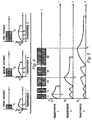
- Figure 3 shows a voltage versus time diagram for a typical prior art RF-ID system.
- the power signal 44 of length t2 which is the amount of time it takes to power up the furthest transponder 48 in a given RF-ID system, is transmitted and the voltage versus time diagrams for the closest 46 and the furthest 48 transponders are shown underneath.
- the closest transponder 46 stores V1 amount of voltage, which is the amount of voltage required by the transponder to return a response, by time t1 which is a very small percentage of the duration of the interrogation signal.
- the closest transponder 46 is exposed to the same pulse and may heat up while it dissipates the excess energy of the interrogation signal.
- the excess energy being dissipated as heat by the close transponder 46 is indicated in the shaded region of the close transponders 46 voltage versus time diagram.
- There is little to no excess energy to be dissipated by the far transponder 48 as seen in its voltage versus time diagram, as transponder 48 requires all the energy absorbed to perform the temperature meansurement, not impaired by heating-up effects, and transmit the transponder response signal.
- Figure 4 shows how varying the length of the interrogation pulse can charge-up transponders having a discharge function, located at different distances from the interrogator, to the same required voltage V1 , without the transponders having to dissipate extra interrogation signal as heat.
- Transponder 1 is located just a short distance from the interrogator, therefore requiring only the minimum interrogation pulse duration t1 to achieve the required voltage V1 to transmit a response signal.
- Transponder 1 receives the interrogation pulse of duration t1 , detects a decrease in the power level of the interrogation pulse and a voltage level V1 , representative of a predetermined amount of power received from the interrogation pulse signal, takes a temperature measurement and transmits a response signal. As shown in Figure 4 , Transponder 1 does not receive any excess interrogation signal which it must dissipate as heat. In a preferred embodiment of the invention, after sending a response signal, Transponder 1 is inactivated for a predetermined amount of time to allow the rest of the Transponders within a given interrogation range to respond.
- Transponder 1 when the interrogator then transmits an interrogation pulse of duration t2 , Transponder 1 does receive the interrogation pulse but is inactivated and does not respond thus intefere with Transponder 2 signal. Instead, Transponder 2 receives the interrogation pulse of duration t2 , takes a temperature measurement and transmits a response signal under the same conditions as Transponder 1 . Because interrogator 9 is transmitting successively longer duration interrogation pulses, instead of the maximum required duration pulses which would charge up the furthest transponder, Transponder 1 , 2 and 3 are activated.
- transponder 25 performs temperature sensor functions via circuit element 38 , and circuit element 38 also provides corrected temperature measurements which are corrected by an over-voltage compensating logic circuit, also a part of circuit element 38 .
- Zener diode 34 and current sensor resistor 36 together form a current sensing over-voltage protection circuit.
- zener diode 34 is chosen such that it will conduct when a higher voltage level exists than that representing the predetermined amount of power required to transmit a transponders response signal has been received from the interrogation signal. In other words, the conduction of the zener diode 34 signifies an over-voltage condition. Upon conduction of zener diode 34 and detection of such conduction by the current sensing element 36 , a signal is transmitted from the current sensing element 36 to the temperature measurement compensating logic circuit of circuit element 38 .
- the temperature measurement compensating logic circuit 38 receives a current level from the current sensing element 36 and combines this information with the amount of time elapsed from the start of current flow, then adjusts the temperature measurement accordingly, thereby compensating for the heat being generated by the excess energy of the interrogation pulse. Once the temperature measurement has been adjusted, the transponder response signal generator of circuit element 38 then transmits a response signal via antenna 26 back to the interrogator of Figure 1 , wherein in one preferred embodiment according to the invention, comprises an identification code and a heat compensated temperature measurement.
- the temperature measurement is performed before the transponder has time to heat up.
- the termination of the interrogation pulse for example, in the first millisecond that a voltage level V1 , representative of a predetermined amount of power received from the interrogation pulse signal is detected, take the temperature measurement and then store the temperature measurement.
- the transponder detects a decrease in the power level of the interrogation signal, retrieve the temperature measurement and transmit the response signal back to the interrogator.
- Interrogator 9 transmits a first minimum duration interrogation pulse of 5 msec in duration.
- Transponder 1 closest to the interrogator 9 charges up to the required voltage V1 with the first interrogation pulse and sends a response signal in return.
- Transponder 1 transmits a response signal back to the interrogator 9 , in a preferred embodiment, Transponder 1 is inactive to transmit another response signal for the predetermined amount of time that it takes for the remainder of the transponders in the interrogation range to respond.
- the receiver 20 of the interrogator does not detect a response signal and the duration of the next interrogation pulse is increased via the Pulse Width Control Circuit 24 .
- the increase is shown to be double the original pulse width.
- Transponders 2 and 3 are further from the interrogator and charge up partially from the first and second 5 msec interrogation pulses, but do not acquire the V1 volts required to return a response signal. Therefore, while Transponder 1 , having received adequate energy from interrogation pulse of duration t1 to respond, is transmitting the response signal, Transponders 2 and 3 are discharging the amount of energy received from the interrogation pulse of duration t1 . Upon transmission of the interrogation pulse of 10 msec duration, Transponder 2 is charged up to a voltage of V1 , initiating a response signal, and subsequently inactivating Transponder 2 .
- the interrogator 9 transmits an interrogation pulse of 10 msec duration, and the receiver 20 of the interrogator does not detect a response signal and, in the embodiment shown, the Pulse Width Control Circuit 24 doubles the duration of the next interrogation pulse to 20 msec.
- Transponder 3 is the furthest of the transponders from the interrogator 9 , thus none of the first four interrogation pulses were of sufficient duration to charge Transponder 3 to the required voltage V1 . However, transmission of the interrogation pulse of 20 msec duration charged Transponder 3 to the voltage V1 , initiating a response signal, and subsequently inactivating Transponder 3 .
- Figures 4 and 5 show a preferred embodiment according to the invention relative to transponders which have discharge functions
- Figure 6 shows a preferred embodiment of the invention relative to transponders which have no discharge function.
- the advantage of using transponders with no discharge function is that the interrogation signal duration does not have to be increased to reach further and further transponders.
- the transponders after receiving any energy from an interrogation signal at all, retain a substantial amount of that energy, and add any new energy received from other interrogation pulses to that existing amount of energy.
- Transponder 60 receives some energy from the first 5 msec, minimum duration, interrogation pulse, and substantially retains that energy.
- Transponder 60 Upon reception of the second 5 msec duration interrogation pulse, Transponder 60 has acquired V1 volts of interrogation energy and is enabled to transmit a response signal.
- Transponder 62 which is further from the interrogator than Transponder 60 , receives some energy from the first two 5 msec interrogation pulses, but because it is further from the interrogator than Transponder 60 , Transponder 62 does not receive as much energy. However, the energy that Transponder 62 has received is retained and upon transmission of a third, 5 msec interrogation pulse, Transponder 62 also acquires V1 volts and transmits a response signal.
- Transponder 64 which is the furthest transponder from the interrogator, also receives and retains energy from the first three, 5 msec interrogation pulses and requires two more, 5 msec interrogation pulses before it has received the necessary V1 volts necessary to transmit a response signal.
- FIG. 6 shows that transponders with no discharge function, located at different distances from the interrogator 9 , can be charged with a series of short, like duration interrogation pulses, the same transponders could be charged with a series of successively longer duration interrogation pulses, as shown in Figure 7 .
- the interrogation process may be expidited by reaching more transponders simultaneously.
- Caution may be desired in the use of this interrogation method with transponders which have no discharge function because the benefits of increased range may be offset by the amount of detrimental overages incurred in many of the transponders reached.
- the pulse duration could be increased up to the 100 % represented by doubling the duration. Actually the increase could be even greater than 100%.
- the interrogator instead of the interrogation pulses having double the duration or some other percentage increase, upon the absence of the response signal, the interrogator could have a circuit which would calculate the probability of a transponder falling within a certain range of the interrogator, and then calculate the required interrogation pulse duration to reach that transponder.
- an interrogation pulse which will potentially power-up many transponders, instead of calculating a specific interrogation pulse duration, increase the duration of the interrogation pulse in much smaller steps.
- This method would be similar to the way that digital transformations of analog data are done. When an analog signal is in a maximum, where there are many data points located in a small area, the digital steps are made very small to increase the accuracy of the measurment.
- the power time control circuit 24 of the interrogator could, when in the vicinity of a distribution maximum, make much smaller incremental changes in the duration of the interrogation pulse.
- the transponders do not have a discharge function and are located beyond the maximum in the distribution of transponders, chances are that they are very close to having the required voltage V1 necessary to send a response signal. Therefore, a decrease in the duration of the interrogation pulse may be necessary to charge-up the transponder without the risk of incurring a detrimental overage.
- FIG 8 shows that in Automobile Vehicle Identification (AVI) applications involving high speed vehicles, the same types of over-voltage problems exist that are shown in the prior art voltage versus time function shown in Figure 3 .
- An antenna 60 embedded in the road has the main lobe and side lobe field characteristics shown in the dotted lines. This field characteristic gives rise to three reading regions designated in the main lobe by "Region B" and the side lobes by "Region A". In the main lobe "Region B", the field strength is great and so a very short power pulse of length t1 is necessary to power up the transponder to the required voltage V1 .
- AVI Automobile Vehicle Identification
- the interrogator optimally sends longer duration pulses, for example 20 msec, when no response from a transponder is detected and the car is still approaching the antenna.
- the interrogator upon detection of a transponder response signal, transmits much shorter duration interrogation pulses, for example 5 msec, because the transponder has been charged by "Region A" of the antenna once and is now in "Region B" of the antenna.
- the interrogator continues to transmit short duration interrogation pulses until the interrogator does not detect a transponders response for a predetermined amount of time, signifying the departure of the transponder from the range of the interrogation antenna.
- the interrogator Upon the absense of the response signal, transmits longer duration pulses again.
Landscapes
- Engineering & Computer Science (AREA)
- Physics & Mathematics (AREA)
- General Physics & Mathematics (AREA)
- Theoretical Computer Science (AREA)
- Health & Medical Sciences (AREA)
- Computer Hardware Design (AREA)
- Microelectronics & Electronic Packaging (AREA)
- Electromagnetism (AREA)
- Toxicology (AREA)
- Computer Networks & Wireless Communication (AREA)
- Computer Vision & Pattern Recognition (AREA)
- Artificial Intelligence (AREA)
- Remote Sensing (AREA)
- Radar, Positioning & Navigation (AREA)
- General Health & Medical Sciences (AREA)
- Signal Processing (AREA)
- Radar Systems Or Details Thereof (AREA)
- Near-Field Transmission Systems (AREA)
Priority Applications (2)
| Application Number | Priority Date | Filing Date | Title |
|---|---|---|---|
| EP98100292A EP0841578B1 (fr) | 1992-04-29 | 1993-04-29 | Méthode de reconnaissance à distance des conditions ambiantes |
| EP98100293A EP0841579B1 (fr) | 1992-04-29 | 1993-04-29 | Système d'identification à distance et de reconnaissance |
Applications Claiming Priority (2)
| Application Number | Priority Date | Filing Date | Title |
|---|---|---|---|
| US87590792A | 1992-04-29 | 1992-04-29 | |
| US875907 | 1992-04-29 |
Related Child Applications (2)
| Application Number | Title | Priority Date | Filing Date |
|---|---|---|---|
| EP98100293A Division EP0841579B1 (fr) | 1992-04-29 | 1993-04-29 | Système d'identification à distance et de reconnaissance |
| EP98100292A Division EP0841578B1 (fr) | 1992-04-29 | 1993-04-29 | Méthode de reconnaissance à distance des conditions ambiantes |
Publications (2)
| Publication Number | Publication Date |
|---|---|
| EP0568067A1 true EP0568067A1 (fr) | 1993-11-03 |
| EP0568067B1 EP0568067B1 (fr) | 1999-03-24 |
Family
ID=25366585
Family Applications (3)
| Application Number | Title | Priority Date | Filing Date |
|---|---|---|---|
| EP98100292A Expired - Lifetime EP0841578B1 (fr) | 1992-04-29 | 1993-04-29 | Méthode de reconnaissance à distance des conditions ambiantes |
| EP98100293A Expired - Lifetime EP0841579B1 (fr) | 1992-04-29 | 1993-04-29 | Système d'identification à distance et de reconnaissance |
| EP93106974A Expired - Lifetime EP0568067B1 (fr) | 1992-04-29 | 1993-04-29 | Système d'identification de radiofréquence avec charge contrÔlée |
Family Applications Before (2)
| Application Number | Title | Priority Date | Filing Date |
|---|---|---|---|
| EP98100292A Expired - Lifetime EP0841578B1 (fr) | 1992-04-29 | 1993-04-29 | Méthode de reconnaissance à distance des conditions ambiantes |
| EP98100293A Expired - Lifetime EP0841579B1 (fr) | 1992-04-29 | 1993-04-29 | Système d'identification à distance et de reconnaissance |
Country Status (4)
| Country | Link |
|---|---|
| EP (3) | EP0841578B1 (fr) |
| JP (1) | JP3288478B2 (fr) |
| KR (1) | KR100251666B1 (fr) |
| DE (3) | DE69327677T2 (fr) |
Cited By (43)
| Publication number | Priority date | Publication date | Assignee | Title |
|---|---|---|---|---|
| EP0723165A1 (fr) * | 1995-01-12 | 1996-07-24 | Texas Instruments Deutschland Gmbh | Perfectionnements relatifs aux communications avec des transpondeurs |
| EP0751401A1 (fr) * | 1995-06-27 | 1997-01-02 | Gec Alsthom Transport Sa | Dispositif permettant de s'affranchir des problèmes de diaphonie lors de la localisation d'un véhicule se déplaçant le long de moyens de propagation d'ondes électromagnétiques |
| FR2752983A1 (fr) * | 1996-08-30 | 1998-03-06 | Toyota Motor Co Ltd | Systeme de mesure de position de vehicule |
| EP0689161A3 (fr) * | 1994-06-24 | 1998-12-23 | Texas Instruments Incorporated | Système d'identification |
| EP0693741A3 (fr) * | 1994-07-20 | 1999-03-03 | Denso Corporation | Dispositif d'identification d'objets mobiles |
| FR2780585A1 (fr) * | 1998-06-30 | 1999-12-31 | Alessandro Manneschi | Appareil et procede pour la detection et la lecture de repondeurs d'identification dans un passage controle |
| EP1043677A1 (fr) * | 1999-04-07 | 2000-10-11 | STMicroelectronics SA | Borne de lecture d'un transpondeur électromagnétique fonctionnant en couplage très proche |
| EP1050839A1 (fr) * | 1999-05-04 | 2000-11-08 | CS Systemes d'Informations | Contrôle de la puissance rayonnée d'un lecteur de carte à circuit intégré de proximité |
| EP1033585A3 (fr) * | 1999-03-03 | 2001-09-05 | DaimlerChrysler AG | Dispositif pour déterminer une distance et système de sécurité employant ce dispositif |
| US6465903B1 (en) | 1998-06-22 | 2002-10-15 | Stmicroelectronics S.A. | Transmission of an operating order via an A.C. supply line |
| US6473028B1 (en) | 1999-04-07 | 2002-10-29 | Stmicroelectronics S.A. | Detection of the distance between an electromagnetic transponder and a terminal |
| US6476709B1 (en) | 1998-06-22 | 2002-11-05 | Stmicroelectronics S.A. | Transmission of digital data over an A.C. supply line |
| WO2003023690A1 (fr) * | 2001-09-13 | 2003-03-20 | Tagtec Limited | Systeme de communication sans fil |
| US6547149B1 (en) | 1999-04-07 | 2003-04-15 | Stmicroelectronics S.A. | Electromagnetic transponder operating in very close coupling |
| US6650226B1 (en) | 1999-04-07 | 2003-11-18 | Stmicroelectronics S.A. | Detection, by an electromagnetic transponder reader, of the distance separating it from a transponder |
| US6703921B1 (en) | 1999-04-07 | 2004-03-09 | Stmicroelectronics S.A. | Operation in very close coupling of an electromagnetic transponder system |
| US6784785B1 (en) | 1999-04-07 | 2004-08-31 | Stmicroelectronics S.A. | Duplex transmission in an electromagnetic transponder system |
| US6879246B2 (en) | 2000-05-12 | 2005-04-12 | Stmicroelectronics S.A. | Evaluation of the number of electromagnetic transponders in the field of a reader |
| WO2005022445A3 (fr) * | 2003-08-29 | 2005-07-07 | Zih Corp | Ensemble coupleur a ligne microruban a champ proche uhf et a selectivite spatiale et systemes rfid utilisant ce dispositif |
| EP1596325A1 (fr) * | 2004-05-14 | 2005-11-16 | St Microelectronics S.A. | Modulation de charge d'un transpondeur |
| US7023391B2 (en) | 2000-05-17 | 2006-04-04 | Stmicroelectronics S.A. | Electromagnetic field generation antenna for a transponder |
| US7046121B2 (en) | 2000-08-09 | 2006-05-16 | Stmicroelectronics S.A. | Detection of an electric signature of an electromagnetic transponder |
| US7049936B2 (en) | 2000-05-12 | 2006-05-23 | Stmicroelectronics S.A. | Validation of the presence of an electromagnetic transponder in the field of a reader |
| US7058357B1 (en) | 1999-07-20 | 2006-06-06 | Stmicroelectronics S.A. | Sizing of an electromagnetic transponder system for an operation in extreme proximity |
| US7263330B2 (en) | 2000-05-12 | 2007-08-28 | Stmicroelectronics S.A. | Validation of the presence of an electromagnetic transponder in the field of a phase demodulation reader |
| US7301470B2 (en) | 1995-01-27 | 2007-11-27 | Steelcase Development Corporation | Electronic system, components and method for tracking files |
| US7398054B2 (en) | 2003-08-29 | 2008-07-08 | Zih Corp. | Spatially selective UHF near field microstrip coupler device and RFID systems using device |
| US7429984B2 (en) | 2005-02-04 | 2008-09-30 | Philip Morris Usa Inc. | Display management system |
| US8130159B2 (en) | 2000-08-17 | 2012-03-06 | Stmicroelectronics S.A. | Electromagnetic field generation antenna for a transponder |
| US8544740B2 (en) | 2004-06-10 | 2013-10-01 | Zih Corp. | Apparatus and method for communicating with an RFID transponder |
| US8624740B2 (en) | 2005-02-04 | 2014-01-07 | Philip Morris Usa Inc. | Controllable RFID card |
| EP2819061A1 (fr) * | 2013-06-27 | 2014-12-31 | Aug. Winkhaus GmbH & Co. KG | Procédé de lecture d'un transpondeur RFID et commande d'une installation de contrôle d'accès |
| US9108434B2 (en) | 2007-12-18 | 2015-08-18 | Zih Corp. | RFID near-field antenna and associated systems |
| DE102015101351A1 (de) * | 2015-01-29 | 2016-08-04 | Balluff Gmbh | System zur kontaktlosen Energie- und Datenübertragung |
| CN106980890A (zh) * | 2017-04-26 | 2017-07-25 | 昆明理工大学 | 一种主动rfid电子标签 |
| CN109584528A (zh) * | 2017-09-28 | 2019-04-05 | 北京同步科技有限公司 | 用于信息发布系统的远程管理装置及其远程管理方法 |
| US11736959B2 (en) | 2006-11-18 | 2023-08-22 | Rfmicron, Inc. | Radio frequency (RF) field strength detecting circuit |
| US11817637B2 (en) | 2006-11-18 | 2023-11-14 | Rfmicron, Inc. | Radio frequency identification (RFID) moisture tag(s) and sensors with extended sensing via capillaries |
| US11831351B2 (en) | 2006-11-18 | 2023-11-28 | Rfmicron, Inc. | Computing device for processing environmental sensed conditions |
| US12073272B2 (en) | 2006-11-18 | 2024-08-27 | Rfmicron, Inc. | Generating a response by a radio frequency identification (RFID) tag within a field strength shell of interest |
| US12099028B2 (en) | 2014-10-08 | 2024-09-24 | Rfmicron, Inc. | Wireless sensor with multiple sensing options |
| US12132468B2 (en) | 2006-11-18 | 2024-10-29 | Rfmicron, Inc. | Method for sensing environmental conditions |
| US12391076B2 (en) | 2006-11-18 | 2025-08-19 | Rfmicron, Inc. | Pressure based wireless sensor and applications thereof |
Families Citing this family (5)
| Publication number | Priority date | Publication date | Assignee | Title |
|---|---|---|---|---|
| DE10060800A1 (de) * | 2000-12-07 | 2002-06-13 | Tbn Identifikation Und Netzwer | System zur Abfrage von Transpondern und Verfahren zur Ansteuerung eines Gates |
| EP1313057B1 (fr) * | 2001-11-20 | 2005-10-26 | Matsushita Electric Industrial Co., Ltd. | Carte à puce sans contact, procède à réponse et programme correspondant |
| US8407097B2 (en) | 2004-04-15 | 2013-03-26 | Hand Held Products, Inc. | Proximity transaction apparatus and methods of use thereof |
| JP4173503B2 (ja) * | 2005-10-19 | 2008-10-29 | 株式会社日立製作所 | Rfidシステムおよびrfidシステムの処理方法 |
| JP2010266274A (ja) * | 2009-05-13 | 2010-11-25 | Alps Electric Co Ltd | センサ装置 |
Citations (3)
| Publication number | Priority date | Publication date | Assignee | Title |
|---|---|---|---|---|
| EP0440153A2 (fr) * | 1990-01-31 | 1991-08-07 | Texas Instruments Deutschland Gmbh | Répondeur |
| EP0442390A1 (fr) * | 1990-02-12 | 1991-08-21 | Texas Instruments Deutschland Gmbh | Répondeur sans pile |
| EP0301127B1 (fr) * | 1987-07-31 | 1993-12-01 | Texas Instruments Deutschland Gmbh | Disposition de répondeur |
Family Cites Families (2)
| Publication number | Priority date | Publication date | Assignee | Title |
|---|---|---|---|---|
| US4075632A (en) * | 1974-08-27 | 1978-02-21 | The United States Of America As Represented By The United States Department Of Energy | Interrogation, and detection system |
| US4114151A (en) * | 1976-09-14 | 1978-09-12 | Alfa-Laval Company Limited | Passive transponder apparatus for use in an interrogator-responder system |
-
1993
- 1993-04-28 KR KR1019930007168A patent/KR100251666B1/ko not_active Expired - Fee Related
- 1993-04-28 JP JP13641593A patent/JP3288478B2/ja not_active Expired - Fee Related
- 1993-04-29 DE DE69327677T patent/DE69327677T2/de not_active Expired - Fee Related
- 1993-04-29 DE DE69327676T patent/DE69327676T2/de not_active Expired - Fee Related
- 1993-04-29 EP EP98100292A patent/EP0841578B1/fr not_active Expired - Lifetime
- 1993-04-29 DE DE69324053T patent/DE69324053T2/de not_active Expired - Fee Related
- 1993-04-29 EP EP98100293A patent/EP0841579B1/fr not_active Expired - Lifetime
- 1993-04-29 EP EP93106974A patent/EP0568067B1/fr not_active Expired - Lifetime
Patent Citations (3)
| Publication number | Priority date | Publication date | Assignee | Title |
|---|---|---|---|---|
| EP0301127B1 (fr) * | 1987-07-31 | 1993-12-01 | Texas Instruments Deutschland Gmbh | Disposition de répondeur |
| EP0440153A2 (fr) * | 1990-01-31 | 1991-08-07 | Texas Instruments Deutschland Gmbh | Répondeur |
| EP0442390A1 (fr) * | 1990-02-12 | 1991-08-21 | Texas Instruments Deutschland Gmbh | Répondeur sans pile |
Cited By (62)
| Publication number | Priority date | Publication date | Assignee | Title |
|---|---|---|---|---|
| EP0689161A3 (fr) * | 1994-06-24 | 1998-12-23 | Texas Instruments Incorporated | Système d'identification |
| EP0693741A3 (fr) * | 1994-07-20 | 1999-03-03 | Denso Corporation | Dispositif d'identification d'objets mobiles |
| US5608406A (en) * | 1995-01-12 | 1997-03-04 | Texas Instruments Incorporated | Device for controlling discharge of a charge capacitor in a transponder |
| EP0723165A1 (fr) * | 1995-01-12 | 1996-07-24 | Texas Instruments Deutschland Gmbh | Perfectionnements relatifs aux communications avec des transpondeurs |
| US7301470B2 (en) | 1995-01-27 | 2007-11-27 | Steelcase Development Corporation | Electronic system, components and method for tracking files |
| US5760733A (en) * | 1995-06-27 | 1998-06-02 | Gec Alsthom Transport Sa | Apparatus for avoiding crosstalk problems when locating a vehicle travelling along means for propagating electromagnetic waves |
| FR2736225A1 (fr) * | 1995-06-27 | 1997-01-03 | Gec Alsthom Transport Sa | Dispositif permettant de s'affranchir des problemes de diaphonie lors de la localisation d'un vehicule se deplacant le long de moyens de propagation d'ondes electromagnetiques |
| EP0751401A1 (fr) * | 1995-06-27 | 1997-01-02 | Gec Alsthom Transport Sa | Dispositif permettant de s'affranchir des problèmes de diaphonie lors de la localisation d'un véhicule se déplaçant le long de moyens de propagation d'ondes électromagnétiques |
| FR2752983A1 (fr) * | 1996-08-30 | 1998-03-06 | Toyota Motor Co Ltd | Systeme de mesure de position de vehicule |
| US6081187A (en) * | 1996-08-30 | 2000-06-27 | Toyota Jidosha Kabushiki Kaisha | Vehicle position detection system |
| US6476709B1 (en) | 1998-06-22 | 2002-11-05 | Stmicroelectronics S.A. | Transmission of digital data over an A.C. supply line |
| US6465903B1 (en) | 1998-06-22 | 2002-10-15 | Stmicroelectronics S.A. | Transmission of an operating order via an A.C. supply line |
| FR2780585A1 (fr) * | 1998-06-30 | 1999-12-31 | Alessandro Manneschi | Appareil et procede pour la detection et la lecture de repondeurs d'identification dans un passage controle |
| EP1033585A3 (fr) * | 1999-03-03 | 2001-09-05 | DaimlerChrysler AG | Dispositif pour déterminer une distance et système de sécurité employant ce dispositif |
| US6346878B1 (en) | 1999-03-03 | 2002-02-12 | Daimlerchrysler Ag | Electronic distance-determining apparatus and electronic security system equipped therewith |
| US6547149B1 (en) | 1999-04-07 | 2003-04-15 | Stmicroelectronics S.A. | Electromagnetic transponder operating in very close coupling |
| US6650226B1 (en) | 1999-04-07 | 2003-11-18 | Stmicroelectronics S.A. | Detection, by an electromagnetic transponder reader, of the distance separating it from a transponder |
| US6473028B1 (en) | 1999-04-07 | 2002-10-29 | Stmicroelectronics S.A. | Detection of the distance between an electromagnetic transponder and a terminal |
| FR2792132A1 (fr) * | 1999-04-07 | 2000-10-13 | St Microelectronics Sa | Borne de lecture d'un transpondeur electromagnetique fonctionnant en couplage tres proche |
| EP1043677A1 (fr) * | 1999-04-07 | 2000-10-11 | STMicroelectronics SA | Borne de lecture d'un transpondeur électromagnétique fonctionnant en couplage très proche |
| US6784785B1 (en) | 1999-04-07 | 2004-08-31 | Stmicroelectronics S.A. | Duplex transmission in an electromagnetic transponder system |
| US6650229B1 (en) | 1999-04-07 | 2003-11-18 | Stmicroelectronics S.A. | Electromagnetic transponder read terminal operating in very close coupling |
| US6703921B1 (en) | 1999-04-07 | 2004-03-09 | Stmicroelectronics S.A. | Operation in very close coupling of an electromagnetic transponder system |
| EP1050839A1 (fr) * | 1999-05-04 | 2000-11-08 | CS Systemes d'Informations | Contrôle de la puissance rayonnée d'un lecteur de carte à circuit intégré de proximité |
| FR2793360A1 (fr) * | 1999-05-04 | 2000-11-10 | Cie Des Signaux | Controle de la puissance rayonnee d'un lecteur de carte a circuit integre de proximite |
| US7058357B1 (en) | 1999-07-20 | 2006-06-06 | Stmicroelectronics S.A. | Sizing of an electromagnetic transponder system for an operation in extreme proximity |
| US6879246B2 (en) | 2000-05-12 | 2005-04-12 | Stmicroelectronics S.A. | Evaluation of the number of electromagnetic transponders in the field of a reader |
| US7263330B2 (en) | 2000-05-12 | 2007-08-28 | Stmicroelectronics S.A. | Validation of the presence of an electromagnetic transponder in the field of a phase demodulation reader |
| US7049936B2 (en) | 2000-05-12 | 2006-05-23 | Stmicroelectronics S.A. | Validation of the presence of an electromagnetic transponder in the field of a reader |
| US7023391B2 (en) | 2000-05-17 | 2006-04-04 | Stmicroelectronics S.A. | Electromagnetic field generation antenna for a transponder |
| US7046121B2 (en) | 2000-08-09 | 2006-05-16 | Stmicroelectronics S.A. | Detection of an electric signature of an electromagnetic transponder |
| US8130159B2 (en) | 2000-08-17 | 2012-03-06 | Stmicroelectronics S.A. | Electromagnetic field generation antenna for a transponder |
| WO2003023690A1 (fr) * | 2001-09-13 | 2003-03-20 | Tagtec Limited | Systeme de communication sans fil |
| US7650114B2 (en) | 2003-08-29 | 2010-01-19 | Zih Corp. | Spatially selective UHF near field microstrip coupler device and RFID systems using device |
| US8160493B2 (en) | 2003-08-29 | 2012-04-17 | Zih Corp. | Spatially selective UHF near field microstrip coupler device and RFID systems using device |
| US7398054B2 (en) | 2003-08-29 | 2008-07-08 | Zih Corp. | Spatially selective UHF near field microstrip coupler device and RFID systems using device |
| EP2272680A3 (fr) * | 2003-08-29 | 2018-02-28 | ZIH Corp. | Dispositif de couplage à microruban de champ proche UHF à sélection spatiale et systèmes RFID utilisant le dispositif |
| CN100464991C (zh) * | 2003-08-29 | 2009-03-04 | Zih公司 | 打印机、近场耦合器、包括收发器的系统以及通信方法 |
| US9852318B2 (en) | 2003-08-29 | 2017-12-26 | Zih Corp. | Spatially selective UHF near field microstrip coupler device and RFID systems using device |
| US8351959B2 (en) | 2003-08-29 | 2013-01-08 | Zih Corp. | Spatially selective UHF near field microstrip coupler device and RFID systems using device |
| WO2005022445A3 (fr) * | 2003-08-29 | 2005-07-07 | Zih Corp | Ensemble coupleur a ligne microruban a champ proche uhf et a selectivite spatiale et systemes rfid utilisant ce dispositif |
| EP1596325A1 (fr) * | 2004-05-14 | 2005-11-16 | St Microelectronics S.A. | Modulation de charge d'un transpondeur |
| US8111140B2 (en) | 2004-05-14 | 2012-02-07 | Stmicroelectronics Sa | Transponder load modulation |
| FR2870406A1 (fr) * | 2004-05-14 | 2005-11-18 | St Microelectronics Sa | Modulation de charge d'un transporteur |
| US8544740B2 (en) | 2004-06-10 | 2013-10-01 | Zih Corp. | Apparatus and method for communicating with an RFID transponder |
| US8596532B2 (en) | 2004-06-10 | 2013-12-03 | Zih Corp. | Apparatus and method for communicating with an RFID transponder |
| US9613242B2 (en) | 2004-06-10 | 2017-04-04 | Zih Corp. | Apparatus and method for communicating with an RFID transponder |
| US7429984B2 (en) | 2005-02-04 | 2008-09-30 | Philip Morris Usa Inc. | Display management system |
| US9292780B2 (en) | 2005-02-04 | 2016-03-22 | Philip Morris Usa Inc. | Controllable RFID card |
| US8624740B2 (en) | 2005-02-04 | 2014-01-07 | Philip Morris Usa Inc. | Controllable RFID card |
| US12391076B2 (en) | 2006-11-18 | 2025-08-19 | Rfmicron, Inc. | Pressure based wireless sensor and applications thereof |
| US12132468B2 (en) | 2006-11-18 | 2024-10-29 | Rfmicron, Inc. | Method for sensing environmental conditions |
| US11831351B2 (en) | 2006-11-18 | 2023-11-28 | Rfmicron, Inc. | Computing device for processing environmental sensed conditions |
| US12073272B2 (en) | 2006-11-18 | 2024-08-27 | Rfmicron, Inc. | Generating a response by a radio frequency identification (RFID) tag within a field strength shell of interest |
| US11736959B2 (en) | 2006-11-18 | 2023-08-22 | Rfmicron, Inc. | Radio frequency (RF) field strength detecting circuit |
| US11817637B2 (en) | 2006-11-18 | 2023-11-14 | Rfmicron, Inc. | Radio frequency identification (RFID) moisture tag(s) and sensors with extended sensing via capillaries |
| US9108434B2 (en) | 2007-12-18 | 2015-08-18 | Zih Corp. | RFID near-field antenna and associated systems |
| EP2819061A1 (fr) * | 2013-06-27 | 2014-12-31 | Aug. Winkhaus GmbH & Co. KG | Procédé de lecture d'un transpondeur RFID et commande d'une installation de contrôle d'accès |
| US12099028B2 (en) | 2014-10-08 | 2024-09-24 | Rfmicron, Inc. | Wireless sensor with multiple sensing options |
| DE102015101351A1 (de) * | 2015-01-29 | 2016-08-04 | Balluff Gmbh | System zur kontaktlosen Energie- und Datenübertragung |
| CN106980890A (zh) * | 2017-04-26 | 2017-07-25 | 昆明理工大学 | 一种主动rfid电子标签 |
| CN109584528A (zh) * | 2017-09-28 | 2019-04-05 | 北京同步科技有限公司 | 用于信息发布系统的远程管理装置及其远程管理方法 |
Also Published As
| Publication number | Publication date |
|---|---|
| DE69324053T2 (de) | 1999-10-07 |
| KR100251666B1 (ko) | 2000-04-15 |
| DE69324053D1 (de) | 1999-04-29 |
| JPH075254A (ja) | 1995-01-10 |
| EP0568067B1 (fr) | 1999-03-24 |
| EP0841578A1 (fr) | 1998-05-13 |
| EP0841579B1 (fr) | 2000-01-19 |
| DE69327677D1 (de) | 2000-02-24 |
| JP3288478B2 (ja) | 2002-06-04 |
| DE69327677T2 (de) | 2000-07-06 |
| DE69327676D1 (de) | 2000-02-24 |
| KR940006359A (ko) | 1994-03-23 |
| EP0841579A1 (fr) | 1998-05-13 |
| EP0841578B1 (fr) | 2000-01-19 |
| DE69327676T2 (de) | 2000-07-06 |
Similar Documents
| Publication | Publication Date | Title |
|---|---|---|
| EP0841579B1 (fr) | Système d'identification à distance et de reconnaissance | |
| JP3138564B2 (ja) | 複数のバッテリーレストランスポンダにインターロゲートするための方法およびリモート識別システム内で使用するためのトランスポンダ | |
| US5451959A (en) | Transponder arrangement | |
| US5444448A (en) | Arrangement interrogation unit for transponder | |
| US5287113A (en) | Voltage limiting batteryless transponder circuit | |
| US6847912B2 (en) | RFID temperature device and method | |
| US6909366B1 (en) | Multi-dimensional electronic identification of articles | |
| US5036308A (en) | Identification system | |
| US5546070A (en) | Device for monitoring the air pressure of a tire in motor vehicles with a sensor | |
| US6905074B2 (en) | Non-contact integrated circuit reader comprising a low power consumption active standby mode | |
| US5355137A (en) | Method of reading the data stored in a passive responder by means of an interrogation device comprising a receiving section | |
| EP0697680B1 (fr) | Procédé de démarrage pour émetteurs-récepteurs mobiles, émetteurs-récepteurs mobiles et fixes correspondants | |
| EP0442390B1 (fr) | Répondeur sans pile | |
| WO2001082213A2 (fr) | Dispositif et procede de controle de sortie d'un lecteur rfid | |
| AU2001253769A1 (en) | RFID reader output control apparatus and method | |
| CA2232256A1 (fr) | Charger un transpondeur dans un systeme de securite | |
| US7876206B2 (en) | Procedure and facility for transmission between a control device and a wheel module | |
| EP1946147B1 (fr) | Systeme de telemetrie courte portee | |
| WO2003081802A1 (fr) | Appareil a frequence radioelectrique sensible a la temperature | |
| US20050088300A1 (en) | Device for exchanging environmental information between a master unit and a slave unit | |
| US6819221B1 (en) | Method of determining a time value representing at least a part of the communication time interval of a transponder with a communication device | |
| EP0919943B1 (fr) | Système de répondeur | |
| JPH10164677A (ja) | 受信装置及び受信データ判別方法 |
Legal Events
| Date | Code | Title | Description |
|---|---|---|---|
| PUAI | Public reference made under article 153(3) epc to a published international application that has entered the european phase |
Free format text: ORIGINAL CODE: 0009012 |
|
| AK | Designated contracting states |
Kind code of ref document: A1 Designated state(s): DE FR GB IT NL |
|
| 17P | Request for examination filed |
Effective date: 19940406 |
|
| 17Q | First examination report despatched |
Effective date: 19960124 |
|
| GRAG | Despatch of communication of intention to grant |
Free format text: ORIGINAL CODE: EPIDOS AGRA |
|
| GRAG | Despatch of communication of intention to grant |
Free format text: ORIGINAL CODE: EPIDOS AGRA |
|
| GRAH | Despatch of communication of intention to grant a patent |
Free format text: ORIGINAL CODE: EPIDOS IGRA |
|
| GRAH | Despatch of communication of intention to grant a patent |
Free format text: ORIGINAL CODE: EPIDOS IGRA |
|
| GRAA | (expected) grant |
Free format text: ORIGINAL CODE: 0009210 |
|
| ITF | It: translation for a ep patent filed | ||
| AK | Designated contracting states |
Kind code of ref document: B1 Designated state(s): DE FR GB IT NL |
|
| REF | Corresponds to: |
Ref document number: 69324053 Country of ref document: DE Date of ref document: 19990429 |
|
| ET | Fr: translation filed | ||
| PLBE | No opposition filed within time limit |
Free format text: ORIGINAL CODE: 0009261 |
|
| 26N | No opposition filed | ||
| REG | Reference to a national code |
Ref country code: GB Ref legal event code: IF02 |
|
| PGFP | Annual fee paid to national office [announced via postgrant information from national office to epo] |
Ref country code: NL Payment date: 20040316 Year of fee payment: 12 |
|
| PGFP | Annual fee paid to national office [announced via postgrant information from national office to epo] |
Ref country code: FR Payment date: 20040402 Year of fee payment: 12 |
|
| PGFP | Annual fee paid to national office [announced via postgrant information from national office to epo] |
Ref country code: DE Payment date: 20040614 Year of fee payment: 12 |
|
| PGFP | Annual fee paid to national office [announced via postgrant information from national office to epo] |
Ref country code: GB Payment date: 20050314 Year of fee payment: 13 |
|
| PG25 | Lapsed in a contracting state [announced via postgrant information from national office to epo] |
Ref country code: IT Free format text: LAPSE BECAUSE OF NON-PAYMENT OF DUE FEES;WARNING: LAPSES OF ITALIAN PATENTS WITH EFFECTIVE DATE BEFORE 2007 MAY HAVE OCCURRED AT ANY TIME BEFORE 2007. THE CORRECT EFFECTIVE DATE MAY BE DIFFERENT FROM THE ONE RECORDED. Effective date: 20050429 |
|
| PG25 | Lapsed in a contracting state [announced via postgrant information from national office to epo] |
Ref country code: NL Free format text: LAPSE BECAUSE OF NON-PAYMENT OF DUE FEES Effective date: 20051101 Ref country code: DE Free format text: LAPSE BECAUSE OF NON-PAYMENT OF DUE FEES Effective date: 20051101 |
|
| PG25 | Lapsed in a contracting state [announced via postgrant information from national office to epo] |
Ref country code: FR Free format text: LAPSE BECAUSE OF NON-PAYMENT OF DUE FEES Effective date: 20051230 |
|
| NLV4 | Nl: lapsed or anulled due to non-payment of the annual fee |
Effective date: 20051101 |
|
| REG | Reference to a national code |
Ref country code: FR Ref legal event code: ST Effective date: 20051230 |
|
| PG25 | Lapsed in a contracting state [announced via postgrant information from national office to epo] |
Ref country code: GB Free format text: LAPSE BECAUSE OF NON-PAYMENT OF DUE FEES Effective date: 20060429 |
|
| GBPC | Gb: european patent ceased through non-payment of renewal fee |
Effective date: 20060429 |