EP0568079A1 - Zweiachsiges Laufwerk für Schienenfahrzeuge - Google Patents
Zweiachsiges Laufwerk für Schienenfahrzeuge Download PDFInfo
- Publication number
- EP0568079A1 EP0568079A1 EP93107001A EP93107001A EP0568079A1 EP 0568079 A1 EP0568079 A1 EP 0568079A1 EP 93107001 A EP93107001 A EP 93107001A EP 93107001 A EP93107001 A EP 93107001A EP 0568079 A1 EP0568079 A1 EP 0568079A1
- Authority
- EP
- European Patent Office
- Prior art keywords
- rotation
- drive according
- axis drive
- clutch
- axle
- Prior art date
- Legal status (The legal status is an assumption and is not a legal conclusion. Google has not performed a legal analysis and makes no representation as to the accuracy of the status listed.)
- Granted
Links
Images
Classifications
-
- B—PERFORMING OPERATIONS; TRANSPORTING
- B61—RAILWAYS
- B61F—RAIL VEHICLE SUSPENSIONS, e.g. UNDERFRAMES, BOGIES OR ARRANGEMENTS OF WHEEL AXLES; RAIL VEHICLES FOR USE ON TRACKS OF DIFFERENT WIDTH; PREVENTING DERAILING OF RAIL VEHICLES; WHEEL GUARDS, OBSTRUCTION REMOVERS OR THE LIKE FOR RAIL VEHICLES
- B61F5/00—Constructional details of bogies; Connections between bogies and vehicle underframes; Arrangements or devices for adjusting or allowing self-adjustment of wheel axles or bogies when rounding curves
- B61F5/38—Arrangements or devices for adjusting or allowing self- adjustment of wheel axles or bogies when rounding curves, e.g. sliding axles, swinging axles
- B61F5/383—Adjustment controlled by non-mechanical devices, e.g. scanning trackside elements
-
- B—PERFORMING OPERATIONS; TRANSPORTING
- B60—VEHICLES IN GENERAL
- B60B—VEHICLE WHEELS; CASTORS; AXLES FOR WHEELS OR CASTORS; INCREASING WHEEL ADHESION
- B60B37/00—Wheel-axle combinations, e.g. wheel sets
- B60B37/06—Wheel-axle combinations, e.g. wheel sets the wheels being integral with, or rigidly attached to, hollow axles
- B60B37/08—Wheel-axle combinations, e.g. wheel sets the wheels being integral with, or rigidly attached to, hollow axles the hollow axles being rotatable around fixed axles
-
- B—PERFORMING OPERATIONS; TRANSPORTING
- B61—RAILWAYS
- B61F—RAIL VEHICLE SUSPENSIONS, e.g. UNDERFRAMES, BOGIES OR ARRANGEMENTS OF WHEEL AXLES; RAIL VEHICLES FOR USE ON TRACKS OF DIFFERENT WIDTH; PREVENTING DERAILING OF RAIL VEHICLES; WHEEL GUARDS, OBSTRUCTION REMOVERS OR THE LIKE FOR RAIL VEHICLES
- B61F3/00—Types of bogies
- B61F3/16—Types of bogies with a separate axle for each wheel
Definitions
- the invention relates to a two-axle running gear for rail vehicles with the features of the preamble of claim 1.
- Two-axis drives for rail vehicles in which the wheel sets are equipped with wheels that can rotate independently of one another are known.
- the sine run of rigid wheel sets ensures uniform, symmetrical wear on the treads, but is also the cause of unstable running conditions at higher speeds.
- drives with idler gear sets do not have a system-typical limit speed. Disadvantages are the centering of the running gear in the track, which is dependent on the wheel-rail profile pairing and is only effected by gravity, and the tendency towards asymmetrical wear of the running surfaces, which is influenced by the design of the wheel bearing.
- the limit speed of a running gear can be increased significantly without having to forego the wear compensation of the sinus run.
- the object of the invention is to control such wheel sets as a function of certain controlled variables do. Since rail vehicles generally have to travel independently of the direction, it is necessary to make the wheel pair coupling dependent on the direction of rotation.
- the decoupling of the wheels in a two-axle running gear for rail vehicles with wheels that can be rotated independently of one another is carried out by a roller bearing arranged centrally between two axle halves.
- a locking element is assigned to the roller bearing, which locks or releases it depending on the direction of rotation.
- the blocking element works either passively depending on the energy supplied to the system or actively depending on selectable control variables.
- the locking element is an activatable clutch, such as a magnetic powder clutch, an electromagnetic friction clutch or a hydraulic clutch, it being equipped with means for detecting the direction of rotation of the axle halves and a control which activates or releases it in accordance with the direction of rotation.
- an activatable clutch such as a magnetic powder clutch, an electromagnetic friction clutch or a hydraulic clutch
- the locking element consists of at least one centrifugal clutch with at least one freewheel, the axle halves being non-positively connected in one direction of rotation by the centrifugal clutch and rotating independently of one another in the other direction of rotation.
- the blocking element or its control characteristic can be designed such that it is deactivated at a higher, definable speed so that all wheels of the drive turn independently of one another at high speed.
- the wheelset leading in the direction of travel is running with the roller bearing locked and the trailing one with released.
- the plug-in axle 2 is fixedly connected to a housing 9 which extends in the direction of the connection of the hollow axle 1 and there encloses a magnetic powder coupling 8 which is fixedly connected to the hollow axle 1 on its outer circumference.
- the housing 9 is freely rotatably supported on the outer circumference of the hollow shaft 1 by ball bearings 9 ', a positive connection being produced between the housing 9 and thus the plug-in shaft 2 and the hollow shaft 1 by activating the magnetic powder coupling 8.
- the hollow axis 1 is provided with a direction of rotation sensor 6 and a controller 5. Depending on the direction of rotation, the controller 5 activates the magnetic particle clutch 8 or enables it. For this, the control is provided with the necessary connecting cables 7, 7 '.
- two axle halves, a thru axle 11 and a hollow axle 12 are rotatably connected to one another via a pair of tapered roller bearings 13 and 14.
- Two roller bearings 15 and 16 on the hollow axle 12 carry a tubular intermediate piece 17, which is arranged around the axle halves in their plug area.
- Both axle halves are provided with flange-like, concentric housing halves 25, 26 which partially surround the intermediate piece 17, but are at a distance from one another.
- the intermediate piece 17 is driven by the hollow axle 12 via a freewheel 18.
- a further freewheel 21 which is arranged between the housing halves 25, 26 on the intermediate piece and is connected to the drive frame 24 via an outer ring 22 and a torque support 23, prevents the intermediate piece 17 from rotating and the two axle halves rotate independently from each other.
Landscapes
- Engineering & Computer Science (AREA)
- Mechanical Engineering (AREA)
- Friction Gearing (AREA)
- Hydraulic Clutches, Magnetic Clutches, Fluid Clutches, And Fluid Joints (AREA)
- Gear Transmission (AREA)
- Arrangement And Mounting Of Devices That Control Transmission Of Motive Force (AREA)
Abstract
Description
- Die Erfindung betrifft ein zweiachsiges Laufwerk für Schienenfahrzeuge mit den Merkmalen des Oberbegriffs des Anspruchs 1.
- Zweiachsige Laufwerke für Schienenfahrzeuge,
bei dem die Radsätze mit unabhängig voneinander drehbaren Rädern ausgerüstet sind, sind bekannt. - Der bei starren Radsätzen vorhandene Sinuslauf sorgt für einen gleichförmigen symmetrischen Verschleiß der Laufflächen, ist aber gleichzeitig Ursache instabiler Laufzustände bei höherer Geschwindigkeit.
- Im Gegensatz zu Laufwerken mit starren Radsätzen weisen Laufwerke mit Losradsätzen keine systemtypische Grenzgeschwindigkeit auf. Von Nachteil ist die von der Rad-Schiene-Profilpaarung abhängige, nur durch die Schwerkraft bewirkte Zentrierung des Laufwerks im Gleis und die von der konstruktiven Ausführung der Radlagerung beeinflußte Neigung zu asymmetrischem Verschleiß der Laufflächen.
- Durch Kombination eines vorlaufenden starren Radsatzes mit einem nachlaufenden Radsatz mit unabhängig voneinander drehbaren Rädern kann die Grenzgeschwindigkeit eines Laufwerks deutlich angehoben werden, ohne auf den Verschleißausgleich des Sinuslaufs verzichten zu müssen.
- Aufgabe der Erfindung ist es, solche Radsätze in Abhängigkeit von bestimmten Regelgrößen steuerbar zu machen. Da Schienenfahrzeuge im allgemeinen richtungsunabhängig verkehren müssen, ist es erforderlich, dabei die Radpaarkoppelung von der Drehrichtung abhängig zu gestalten.
- Diese Aufgabe wird mit den im kennzeichnenden Teil des Anspruchs 1 genannten Merkmalen gelöst. Fortbildungen und besondere Ausführungen der Erfindung sind in den weiteren Ansprüchen umfaßt.
- Erfindungsgemäß erfolgt die Entkoppelung der Räder bei einem zweiachsigen Laufwerk für Schienenfahrzeuge mit unabhängig voneinander drehbaren Rädern durch ein zentral zwischen zwei Achshälften angeordnetes Wälzlager. Dem Wälzlager ist ein Sperrelement zugeordnet, das es je nach Drehrichtung sperrt oder freigibt.
- Das Sperrelement arbeitet entweder passiv in Abhängigkeit von der dem System zugeführten Energie oder aktiv in Abhängigkeit wählbarer Regelgrößen.
- Nach einer Ausführung der Erfindung ist das Sperrelement eine aktivierbare Kupplung, wie eine Magnetpulverkupplung, eine elektromagnetische Reibungskupplung oder eine hydraulische Kupplung, wobei es mit Mitteln zur Erkennung der Drehrichtung der Achshälften und einer Steuerung ausgestattet ist, die es entsprechend der Drehrichtung aktiviert oder freischaltet.
- Nach einer zweiten Ausführung der Erfindung besteht das Sperrelement aus wenigstens einer Fliehkraftkupplung mit wenigstens einem Freilauf, wobei die Achshälften in der einen Drehrichtung durch die Fliehkraftkupplung kraftschlüssig verbunden sind und in der anderen Drehrichtung durch den Freilauf unabhängig voneinander drehen.
- Vorteilhafterweise kann das Sperrelement oder seine Regelcharakteristik so ausgeführt werden, daß es bei einer höheren, definierbaren Drehzahl außer Funktion gesetzt wird, damit bei hoher Geschwindigkeit alle Räder des Laufwerks unabhängig voneinander drehen.
- Mit den genannten Maßnahmen wird bewirkt, daß jeweils der in Fahrtrichtung führende Radsatz mit gesperrtem und der nachlaufende mit freigegebenem Wälzlager läuft.
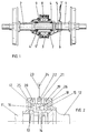
- Im Folgenden wird die Erfindung anhand von Zeichnungen beispielhaft näher beschrieben. Dabei zeigen:
- Fig. 1)
- einen Radsatz eines Laufwerks mit Wälzlagern und Magnetpulverkupplung;
- Fig. 2)
- die Verbindung von zwei Achshälften mit Wälzlager und Fliehkraftkupplung.
- Der Radsatz gemäß Fig. 1 besteht aus zwei Achshälften, wobei die eine Hälfte als Steckachse 2 und die andere Hälfte als Hohlachse 1 ausgebildet ist. Steckachse 2 und Hohlachse 1 sind ineinander über Wälzlager 4 gelagert. Die Steckachse 2 ist mit einem Gehäuse 9 fest verbunden, das sich in Richtung auf die Verbindung der Hohlachse 1 erstreckt und dort eine Magnetpulverkupplung 8 umschließt, die mit der Hohlachse 1 an ihrem äußeren Umfang fest verbunden ist. Das Gehäuse 9 ist auf dem äußeren Umfang der Hohlachse 1 durch Kugellager 9' frei drehbar gelagert, wobei durch Aktivierung der Magnetpulverkupplung 8 eine kraftschlüssige Verbindung zwischen dem Gehäuse 9 und damit der Steckachse 2 und der Hohlachse 1 hergestellt wird. Die Hohlachse 1 ist mit einem Drehrichtungssensor 6 und einer Steuerung 5 versehen. Je nach Drehrichtung aktiviert die Steuerung 5 die Magnetpulverkupplung 8, oder schaltet sie frei. Hierfür ist die Steuerung mit den erforderlichen Verbindungskabeln 7, 7' versehen.
- In Fig. 2 sind zwei Achshälften, eine Steckachse 11 und eine Hohlachse 12 über ein Kegelrollenlagerpaar 13 und 14 drehbar miteinander verbunden. Zwei Wälzlager 15 und 16 auf der Hohlachse 12 tragen ein rohrförmiges Zwischenstück 17, das um die Achshälften in deren Steckbereich angeordnet ist. Beide Achshälften sind mit flanschartigen, konzentrischen Gehäusehälften 25, 26 versehen, die das Zwischenstück 17 teilweise umschließen, jedoch einen Abstand zueinander aufweisen. In einer Drehrichtung wird das Zwischenstück 17 über einen Freilauf 18 von der Hohlachse 12 angetrieben. Über zwei Fliehkraftkupplungen 19 und 20, die zwischen dem Zwischenstück 17 und jeweils einer Gehäusehälfte 25, 26 angeordnet sind, werden in dieser Drehrichtung die beiden Achshälften 11, 12 kraftschlüssig miteinander verbunden. In der entgegengesetzten Drehrichtung verhindert ein weiterer Freilauf 21, der zwischen den Gehäusehälften 25, 26 auf dem Zwischenstück angeordnet ist und über einen äußeren Ring 22 und eine Drehmomentstütze 23 mit dem Laufwerksrahmen 24 verbunden ist, das Mitdrehen des Zwischenstücks 17 und die beiden Achshälften drehen unabhängig voneinander.
Claims (7)
- Zweiachsiges Laufwerk für Schienenfahrzeuge, bei dem die Radsätze mit unabhängig voneinander drehbaren Rädern ausgerüstet sind,
dadurch gekennzeichnet,
daß die Entkoppelung der Räder durch ein zentral zwischen zwei Achshälften (1, 2, 11, 12) angeordnetes Wälzlager (4, 13, 14) erfolgt. - Zweiachsiges Laufwerk nach Anspruch 1,
dadurch gekennzeichnet,
daß dem Wälzlager (4, 13, 14) ein Sperrelement zugeordnet ist, das je nach Drehrichtung das Wälzlager (4, 13, 14) sperrt oder freigibt. - Zweiachsiges Laufwerk nach Anspruch 2,
dadurch gekennzeichnet,
daß das Sperrelement passiv in Abhängigkeit von der dem System zugeführten Energie oder aktiv in Abhängigkeit wählbarer Regelgrößen arbeitet. - Zweiachsiges Laufwerk nach Anspruch 3,
dadurch gekennzeichnet,
daß das Sperrelement eine aktivierbare Kupplung, wie eine Magnetpulverkupplung (8), eine elektromagnetische Reibungskupplung oder eine hydraulische Kupplung ist,
wobei das Sperrelement mit Mitteln zur Erkennung der Drehrichtung der Achshälften und einer Steuerung ausgestattet ist, die es entsprechend der Drehrichtung aktiviert oder freischaltet. - Zweiachsiges Laufwerk nach Anspruch 3,
dadurch gekennzeichnet,
daß das Sperrelement aus wenigstens einer Fliehkraftkupplung (19, 20) mit wenigstens einem Freilauf (18, 21) besteht,
wobei die Achshälften (11, 12) in der einen Drehrichtung durch die Fliehkraftkupplung (19, 20) kraftschlüssig verbunden sind und in der anderen Drehrichtung durch den Freilauf unabhängig voneinander drehen. - Zweiachsiges Laufwerk nach einem der Ansprüche 3 bis 5,
dadurch gekennzeichnet,
daß das Sperrelement oder seine Regelcharakteristik so ausgeführt ist,
daß es bei einer höheren, definierbaren Drehzahl außer Funktion gesetzt wird. - Zweiachsiges Laufwerk nach einem der vorhergehenden Ansprüche,
dadurch gekennzeichnet,
daß jeweils der in Fahrtrichtung führende Radsatz mit gesperrtem und der nachlaufende mit freigegebenem Wälzlager läuft.
Applications Claiming Priority (2)
| Application Number | Priority Date | Filing Date | Title |
|---|---|---|---|
| DE4213956 | 1992-04-29 | ||
| DE4213956 | 1992-04-29 |
Publications (2)
| Publication Number | Publication Date |
|---|---|
| EP0568079A1 true EP0568079A1 (de) | 1993-11-03 |
| EP0568079B1 EP0568079B1 (de) | 1996-09-11 |
Family
ID=6457654
Family Applications (1)
| Application Number | Title | Priority Date | Filing Date |
|---|---|---|---|
| EP93107001A Expired - Lifetime EP0568079B1 (de) | 1992-04-29 | 1993-04-29 | Zweiachsiges Laufwerk für Schienenfahrzeuge |
Country Status (3)
| Country | Link |
|---|---|
| EP (1) | EP0568079B1 (de) |
| AT (1) | ATE142565T1 (de) |
| DE (1) | DE59303710D1 (de) |
Cited By (4)
| Publication number | Priority date | Publication date | Assignee | Title |
|---|---|---|---|---|
| DE9417281U1 (de) * | 1994-10-27 | 1995-04-20 | Meinke, Peter, Prof. Dr.-Ing., 82319 Starnberg | Eisenbahnradsatz |
| RU2440907C2 (ru) * | 2010-02-01 | 2012-01-27 | Государственное образовательное учреждение высшего профессионального образования "Иркутский государственный университет путей сообщения" (ИрГУПС (ИрИИТ)) | Тележка грузового вагона |
| EP2692607A1 (de) * | 2012-08-01 | 2014-02-05 | Bombardier Transportation GmbH | Fahrwerk für Schienenfahrzeug mit lösbarer starrer Verbindung zwischen den Rädern |
| RU2570520C1 (ru) * | 2014-08-07 | 2015-12-10 | Открытое акционерное общество Научно-исследовательский и конструкторско-технологический институт подвижного состава (ОАО "ВНИКТИ") | Экипаж рельсового транспортного средства |
Citations (3)
| Publication number | Priority date | Publication date | Assignee | Title |
|---|---|---|---|---|
| EP0188687A2 (de) * | 1985-01-18 | 1986-07-30 | Messerschmitt-Bölkow-Blohm Gesellschaft mit beschränkter Haftung | Radsatz für Schienenfahrzeuge |
| DE3538779C1 (de) * | 1985-10-31 | 1986-08-07 | Messerschmitt-Bölkow-Blohm GmbH, 8012 Ottobrunn | Radsatz fuer Schienenfahrzeuge |
| CH657327A5 (en) * | 1982-08-18 | 1986-08-29 | Paul Konrad Renkewitz | Wheel axle for rail vehicles |
-
1993
- 1993-04-29 EP EP93107001A patent/EP0568079B1/de not_active Expired - Lifetime
- 1993-04-29 DE DE59303710T patent/DE59303710D1/de not_active Expired - Fee Related
- 1993-04-29 AT AT93107001T patent/ATE142565T1/de not_active IP Right Cessation
Patent Citations (3)
| Publication number | Priority date | Publication date | Assignee | Title |
|---|---|---|---|---|
| CH657327A5 (en) * | 1982-08-18 | 1986-08-29 | Paul Konrad Renkewitz | Wheel axle for rail vehicles |
| EP0188687A2 (de) * | 1985-01-18 | 1986-07-30 | Messerschmitt-Bölkow-Blohm Gesellschaft mit beschränkter Haftung | Radsatz für Schienenfahrzeuge |
| DE3538779C1 (de) * | 1985-10-31 | 1986-08-07 | Messerschmitt-Bölkow-Blohm GmbH, 8012 Ottobrunn | Radsatz fuer Schienenfahrzeuge |
Non-Patent Citations (1)
| Title |
|---|
| REVUE GÉNÉRALE DES CHEMINS DE FER Nr. 5, 1981, PARIS Seiten 315 - 316 'Bogie ferroviaire avec roues indépendantes en rotation' SEITE 315 : FIGUR RECHTS UNTEN * |
Cited By (4)
| Publication number | Priority date | Publication date | Assignee | Title |
|---|---|---|---|---|
| DE9417281U1 (de) * | 1994-10-27 | 1995-04-20 | Meinke, Peter, Prof. Dr.-Ing., 82319 Starnberg | Eisenbahnradsatz |
| RU2440907C2 (ru) * | 2010-02-01 | 2012-01-27 | Государственное образовательное учреждение высшего профессионального образования "Иркутский государственный университет путей сообщения" (ИрГУПС (ИрИИТ)) | Тележка грузового вагона |
| EP2692607A1 (de) * | 2012-08-01 | 2014-02-05 | Bombardier Transportation GmbH | Fahrwerk für Schienenfahrzeug mit lösbarer starrer Verbindung zwischen den Rädern |
| RU2570520C1 (ru) * | 2014-08-07 | 2015-12-10 | Открытое акционерное общество Научно-исследовательский и конструкторско-технологический институт подвижного состава (ОАО "ВНИКТИ") | Экипаж рельсового транспортного средства |
Also Published As
| Publication number | Publication date |
|---|---|
| DE59303710D1 (de) | 1996-10-17 |
| ATE142565T1 (de) | 1996-09-15 |
| EP0568079B1 (de) | 1996-09-11 |
Similar Documents
| Publication | Publication Date | Title |
|---|---|---|
| DE3828083C2 (de) | Vierrad-Antriebssystem für ein Fahrzeug | |
| DE2105123A1 (de) | Kraftfahrzeug Radlagersatz | |
| EP0698540B1 (de) | Angetriebenes Fahrwerk für Schienenfahrzeuge | |
| DE2556177B2 (de) | Lagerungsanordnung einer über ein Gleichlaufdrehgelenk antreibbaren Radnabe | |
| DE19547981A1 (de) | Rad-Enden-Anordnung | |
| DE4214077A1 (de) | Antriebskraft-uebertragungsvorrichtung | |
| EP0816127B1 (de) | Radlagerung einer angetriebenen Achse mit einem hohlen, die Radlasten aufnehmenden Achskörper | |
| EP0151965B1 (de) | Elektrohängebahn | |
| EP0965511B1 (de) | Achseinheit für Schienenfahrzeuge | |
| DE19954590A1 (de) | Antriebsanordnung mit einem Elektromotor | |
| EP0043340B1 (de) | Schienengebundenes elektrisches Triebfahrzeug | |
| EP0188687B1 (de) | Radsatz für Schienenfahrzeuge | |
| EP0568079B1 (de) | Zweiachsiges Laufwerk für Schienenfahrzeuge | |
| EP0279889B1 (de) | Lagerung eines Zwischenrades eines Allrad-Verteilergetriebes | |
| EP0958229B1 (de) | Seilzug mit vereinfachter montage | |
| DE2259035B2 (de) | Anordnung zur Spurführung von Radsätzen | |
| EP0013895B1 (de) | Antriebsanordnung für lose Laufräder eines Schienenfahrzeuges | |
| EP1532033B1 (de) | Triebgestell für ein schienenfahrzeug | |
| DE102021209955B4 (de) | Getriebe für ein Flurförderfahrzeug sowie Flurförderfahrzeug mit dem Getriebe | |
| DE202016004280U1 (de) | Schienengebundenes Transportsystem mit wenigstens einem Fahrwerk | |
| EP1199237B1 (de) | Getriebe für Schienenfahrzeuge | |
| DE2517755A1 (de) | Rolle fuer das reprofilieren eines radsatzes | |
| DE3218088C2 (de) | ||
| EP1149009B1 (de) | Losradachse für schienenfahrzeuge | |
| DE3817211A1 (de) | Radsatz fuer schienenfahrzeuge |
Legal Events
| Date | Code | Title | Description |
|---|---|---|---|
| PUAI | Public reference made under article 153(3) epc to a published international application that has entered the european phase |
Free format text: ORIGINAL CODE: 0009012 |
|
| AK | Designated contracting states |
Kind code of ref document: A1 Designated state(s): AT CH DE FR IT LI |
|
| 17P | Request for examination filed |
Effective date: 19940125 |
|
| RAP1 | Party data changed (applicant data changed or rights of an application transferred) |
Owner name: AEG SCHIENENFAHRZEUGE GMBH |
|
| 17Q | First examination report despatched |
Effective date: 19950405 |
|
| GRAG | Despatch of communication of intention to grant |
Free format text: ORIGINAL CODE: EPIDOS AGRA |
|
| GRAH | Despatch of communication of intention to grant a patent |
Free format text: ORIGINAL CODE: EPIDOS IGRA |
|
| GRAG | Despatch of communication of intention to grant |
Free format text: ORIGINAL CODE: EPIDOS AGRA |
|
| GRAH | Despatch of communication of intention to grant a patent |
Free format text: ORIGINAL CODE: EPIDOS IGRA |
|
| GRAA | (expected) grant |
Free format text: ORIGINAL CODE: 0009210 |
|
| RAP1 | Party data changed (applicant data changed or rights of an application transferred) |
Owner name: ABB DAIMLER-BENZ TRANSPORTATION (DEUTSCHLAND) GMBH |
|
| AK | Designated contracting states |
Kind code of ref document: B1 Designated state(s): AT CH DE FR IT LI |
|
| REF | Corresponds to: |
Ref document number: 142565 Country of ref document: AT Date of ref document: 19960915 Kind code of ref document: T |
|
| REG | Reference to a national code |
Ref country code: CH Ref legal event code: NV Representative=s name: ROTTMANN, ZIMMERMANN + PARTNER AG |
|
| ET | Fr: translation filed | ||
| REF | Corresponds to: |
Ref document number: 59303710 Country of ref document: DE Date of ref document: 19961017 |
|
| ITF | It: translation for a ep patent filed | ||
| PLBE | No opposition filed within time limit |
Free format text: ORIGINAL CODE: 0009261 |
|
| 26N | No opposition filed | ||
| REG | Reference to a national code |
Ref country code: CH Ref legal event code: PFA Free format text: ABB DAIMLER-BENZ TRANSPORTATION (DEUTSCHLAND) GMBH TRANSFER- DAIMLERCHRYSLER RAIL SYSTEMS GMBH |
|
| PGFP | Annual fee paid to national office [announced via postgrant information from national office to epo] |
Ref country code: CH Payment date: 20020319 Year of fee payment: 10 |
|
| PGFP | Annual fee paid to national office [announced via postgrant information from national office to epo] |
Ref country code: AT Payment date: 20020328 Year of fee payment: 10 |
|
| PGFP | Annual fee paid to national office [announced via postgrant information from national office to epo] |
Ref country code: FR Payment date: 20020416 Year of fee payment: 10 |
|
| PGFP | Annual fee paid to national office [announced via postgrant information from national office to epo] |
Ref country code: DE Payment date: 20020418 Year of fee payment: 10 |
|
| PG25 | Lapsed in a contracting state [announced via postgrant information from national office to epo] |
Ref country code: AT Free format text: LAPSE BECAUSE OF NON-PAYMENT OF DUE FEES Effective date: 20030429 |
|
| PG25 | Lapsed in a contracting state [announced via postgrant information from national office to epo] |
Ref country code: LI Free format text: LAPSE BECAUSE OF NON-PAYMENT OF DUE FEES Effective date: 20030430 Ref country code: CH Free format text: LAPSE BECAUSE OF NON-PAYMENT OF DUE FEES Effective date: 20030430 |
|
| PG25 | Lapsed in a contracting state [announced via postgrant information from national office to epo] |
Ref country code: DE Free format text: LAPSE BECAUSE OF NON-PAYMENT OF DUE FEES Effective date: 20031101 |
|
| REG | Reference to a national code |
Ref country code: CH Ref legal event code: PL |
|
| PG25 | Lapsed in a contracting state [announced via postgrant information from national office to epo] |
Ref country code: FR Free format text: LAPSE BECAUSE OF NON-PAYMENT OF DUE FEES Effective date: 20031231 |
|
| REG | Reference to a national code |
Ref country code: FR Ref legal event code: ST |
|
| PG25 | Lapsed in a contracting state [announced via postgrant information from national office to epo] |
Ref country code: IT Free format text: LAPSE BECAUSE OF NON-PAYMENT OF DUE FEES Effective date: 20050429 |