EP0568193A2 - Method and apparatus for determining particle response characteristics of a device - Google Patents
Method and apparatus for determining particle response characteristics of a device Download PDFInfo
- Publication number
- EP0568193A2 EP0568193A2 EP93302447A EP93302447A EP0568193A2 EP 0568193 A2 EP0568193 A2 EP 0568193A2 EP 93302447 A EP93302447 A EP 93302447A EP 93302447 A EP93302447 A EP 93302447A EP 0568193 A2 EP0568193 A2 EP 0568193A2
- Authority
- EP
- European Patent Office
- Prior art keywords
- particles
- input
- output
- counts
- particle
- Prior art date
- Legal status (The legal status is an assumption and is not a legal conclusion. Google has not performed a legal analysis and makes no representation as to the accuracy of the status listed.)
- Granted
Links
Images




Classifications
-
- G—PHYSICS
- G01—MEASURING; TESTING
- G01N—INVESTIGATING OR ANALYSING MATERIALS BY DETERMINING THEIR CHEMICAL OR PHYSICAL PROPERTIES
- G01N15/00—Investigating characteristics of particles; Investigating permeability, pore-volume or surface-area of porous materials
- G01N15/06—Investigating concentration of particle suspensions
-
- G—PHYSICS
- G01—MEASURING; TESTING
- G01N—INVESTIGATING OR ANALYSING MATERIALS BY DETERMINING THEIR CHEMICAL OR PHYSICAL PROPERTIES
- G01N15/00—Investigating characteristics of particles; Investigating permeability, pore-volume or surface-area of porous materials
- G01N15/06—Investigating concentration of particle suspensions
- G01N15/065—Investigating concentration of particle suspensions using condensation nuclei counters
-
- G—PHYSICS
- G01—MEASURING; TESTING
- G01N—INVESTIGATING OR ANALYSING MATERIALS BY DETERMINING THEIR CHEMICAL OR PHYSICAL PROPERTIES
- G01N21/00—Investigating or analysing materials by the use of optical means, i.e. using sub-millimetre waves, infrared, visible or ultraviolet light
- G01N21/84—Systems specially adapted for particular applications
- G01N21/85—Investigating moving fluids or granular solids
-
- G—PHYSICS
- G01—MEASURING; TESTING
- G01N—INVESTIGATING OR ANALYSING MATERIALS BY DETERMINING THEIR CHEMICAL OR PHYSICAL PROPERTIES
- G01N21/00—Investigating or analysing materials by the use of optical means, i.e. using sub-millimetre waves, infrared, visible or ultraviolet light
- G01N21/84—Systems specially adapted for particular applications
- G01N21/88—Investigating the presence of flaws or contamination
- G01N21/94—Investigating contamination, e.g. dust
Definitions
- the present invention relates to a method of and an apparatus for determining a particle response characteristic of a device in order to model the degree to which contaminants present within a fluid passing through the device will be delayed or retained within the device. More particularly, the present invention relates to such a method and apparatus in which pulses of particles are introduced into a fluid before the fluid passes into the device to derive statistically repeatable reference and response pulses which form the particle response characteristic of the device.
- Ultra-high purity gases pass through much of the equipment, for example, process piping, valves, flow meters, rapid thermal processors etc., used in the manufacture of semiconductors.
- the equipment Prior to use, the equipment is purged with an ultra-high purity gas to eliminate possible contaminants. For instance, during the loading of wafers into a process chamber of a rapid thermal processor, the process chamber is exposed to ambient air. Air, however, contains moisture which is an undesirable contaminant in the semiconductor manufacturing process. Therefore, the process chamber is purged with an inert stream of gas, generally composed of ultra-high purity nitrogen.
- the dry down characteristics of the process chamber are measured with a moisture analyser to determine the length of time required to purge the process chamber so that a sufficiently low level of moisture will exist within the process chamber.
- a method of determining a particle response characteristic of a device comprises the steps of:
- an input pulse of particles is introduced into a flowing fluid. Thereafter, the flowing fluid is introduced into the device (step (b)), after the introduction of the input pulse of particles, so that an output pulse of particles is present in the fluid after the fluid has passed through the device.
- steps (c), (d), (e) and (f) input and output counts of particles produced by the input and output pulses of particles, respectively, on a particle count versus time basis, are measured and recorded.
- steps (a), (b), (c), (d), (e) and (f) are repeated such that a sufficient number of input and output counts of particles are produced that signal averaging of the input and output counts of particles produces statistically repeatable reference and response counts of particles, respectively, on the particle count versus time basis.
- Input and response counts of particles are determined in accordance with a step (e) of the method from the recorded input and output counts of particles by signal averaging the input and output counts of particles. A comparison between the reference and response counts of particles is the particle response characteristic of the device.
- an apparatus suitable for use in determining a particle response characteristic of a device is characterised by fluid means for creating a flowing fluid; input pulse introduction means for generating and introducing input pulses of particles into the flowing fluid, the input pulse introduction means being adapted to be connected to the device such that output pulses of particles are present in the flowing fluid after the flowing fluid has passed through the device; the input pulse introduction means being adapted to repeatedly generate input pulses of particles, and therefore, the output pulses of particles such that a sufficient number of input and output counts of particles, on a particle count versus time basis, are produced from the input and output pulses of particles, respectively, that signal averaging of the input and output counts of particles produces statistically repeatable reference and response pulses of particles, respectively; measuring means adapted to be selectively connected to the input pulse introduction means and the device for measuring the input and output counts of particles; and recording means for recording the input and output counts of particles, whereby a comparison between the reference and response pulses of particles is the particle response characteristic of the device.
- the apparatus defined above comprises a fluid means for creating a fluid.
- An input pulse introduction means is provided for repeatedly generating and introducing input pulses of particles into the flowing fluid before the flowing fluid passes into the device.
- the input pulse introduction means is adapted to be connected to the device such that output pulses of the particles are present in the flowing fluid after the flowing fluid is passed through the device.
- the input pulse introduction means is adapted to repeatedly generate input pulses of the particles and, therefore, the output pulses of the particles such that a sufficient number of input and output counts of particles, on a particle versus time basis, are produced from the input and output pulses of particles, respectively, that signal averaging of the input and output counts of the particles produces statistically repeatable reference and response counts of particles, respectively, again, on the particle count versus time basis.
- a recording means is provided for recording the input and output counts of particles. The signal averaging of the input and output counts of the particles determines the reference and response counts of particles. A comparison between the reference and response pulses of particles is the particle response characteristic of the
- the comparison between the reference and response counts of particles is the particle response characteristic of the device.
- the particle response characteristic of a device is a model of the degree to which contaminants present within a fluid being passed through a device will be delayed or retained within the device.
- the time lag between the reference and response counts is indicative of the effective volume of the device.
- the effective volume in the present context is the volume of the device which the fluid traverses as it passes through the device.
- the effective volume may differ from the geometrical volume of the device as a result of the flow pattern of the fluid through the device.
- This aspect of the particle response characteristic of a device can be used to select devices that have a minimum effective volume and therefore, presumably retain the least amount of contaminants.
- the time lag is useful for synchronisation of analytical and process equipment.
- sampling systems consisting of tubing, fittings, valves and gauges are typically used to connect process equipment with analytical instrumentation.
- the time required for the fluid to pass through the sampling system must be known if the detected quantity is to be related to events occurring in the particular piece of process equipment.
- the particle response characteristic provides a precise means for establishing synchronisation.
- Another aspect is a comparison that involves taking a difference between the half height widths of the reference and response count curves (plotted curves of particle count versus time). This difference indicates the time resolution that is possible in the device. For instance, changes in particle counts which occur at time intervals that are less than the time resolution cannot be observed.
- This feature can be used to select appropriate time intervals for sampling contaminants present in a fluid being discharged from a device to assure that the count of the sampled contaminants reflect the state of the fluid as discharged from the device. If particular sampling time intervals are required, sampling systems can be designed and selected that will allow sampling to take place within such sampling time intervals.
- an apparatus 10 is illustrated in accordance with the present invention for use in determining a particle response characteristic of a device, such as a valve, rotameter, sampling tube, or other equipment used in connection with the distribution or use of an ultra-high purity gas.
- a device such as a valve, rotameter, sampling tube, or other equipment used in connection with the distribution or use of an ultra-high purity gas.
- the present invention has particular application to devices involved in ultra-high purity gas distribution and uses, it also has general applicability to devices in which any type of fluid passes through the device during the use of the device.
- apparatus 10 includes a particle generator 12 that is specifically designed to introduce particles into a gas stream to be passed through a device.
- Particle generator 12 consists of a housing 13 that can be formed of a T-like fitting having three legs. In one leg, a feed through 14 is provided for supporting a filament 18 within the T-like fitting.
- filament 18 is raised to a high enough temperature to effect a reaction between the filament 18 and the gas surrounding filament 18. If during the application of electrical power, a gas such as nitrogen is passed through the other two in-line legs of the T-like fitting, particles will be created that substantially comprise nitrides of Tungsten such as WN 4 .
- the amount of particles that are created is dependent upon the power applied through filament 18 and duration of time that the power is applied.
- gases and filaments other than tungsten can be used which will produce discrete particles when an electrical current is passed through a filament.
- oxygen can be used to create particles formed of oxides of Tungsten such as W0 3 or W 4 0 4 or mixtures of nitrogen and oxygen can be used in any proportion with or without the presence of additional components, for instance air.
- Particle generator 12 is illustrated as being connected between a gas source 20 and a device 22 along the two in-line legs of the T-like fitting forming housing 13 thereof. Particles produced by particle generator 12 will be introduced into the gas stream and will enter device 22 through entrainment within gas flowing from gas source 20 into particle generator 12. The input pulse of particles will produce an output pulse in response to such input pulse after the gas passes through device 22. The output pulses are sensed or measured by either a condensation nucleus counter 24 or a laser particle counter 26. At very high particle counts, the condensation nucleus counter will be overwhelmed, and at very low particle counts, the laser particle counter will be ineffective to sense the particles. Hence, the use of two particle counters ensures that particles will be counted over a range that encompasses both high and very low particle counts.
- the input counts of particles are signal averaged to produce a reference count of particles and the output counts of particles are then signal averaged to produce a response count of particles.
- the number of repetitions of input and output count measurements is a number that is determined to be that which will yield statistically repeatable reference and response pulses. That is, if for instance, 10 input and output pulses are produced and particle counts recorded and then signal averaged, the reference and response counts of particles will remain essentially unchanged no matter how many different times the experiment is carried out.
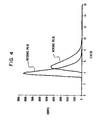
- FIG. 4 Such a particle response characteristic plot for a 12.7 cm. long, approximately 9.5 mm. in diameter, electropolished stainless steel sampling tube is reproduced herein as Figure 4.
- This plot shows that the sampling tube has a time resolution of approximately a half a second by comparing the widths of the curves representing the reference and response counts of particles at the half heights of such curves. Thus, changes in particle or contaminant count that are taking place at less than a half second will merge to an average and will not be detectable through such a sampling tube.
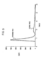
- Figure 5 the plot of the particle response characteristic of a rotameter is illustrated. This plot shows that a rotameter has such a lagging response that one would not put such a device in a flow circuit through which contaminants are to be measured, such as moisture, because moisture would tend to collect in such a device.
- Input and output pulses after being sensed by particle counters 24 and 26 are acquired by a counter board 30 installed in an expansion slot of a PC 31, or otherwise connected to some other programmable logic computer.
- Counter board 30 also serves to trigger particle generator 12 and to record the input and output pulses of particles by writing them to files contained within the PC 31. This is accomplished by a program written in MICROSOFT QUICKBASIC that is used to control the operation of counter board 30, preferably a KEITHLEY/METRABYTE CTM-05 counter board, installed in PC 31 which is also provided with a VGA board and monitor.
- Counter board 30 can be obtained from Keithley/Metrabyte/Asyst/DAC, 440 Myles Standish Blvd., Taunton, Ma 02780.
- the CTM-05 board will record data and also control particle generator 12.
- the CTM-05 board is then initialised and the counters are set up.
- the CTM-05 board has five counters of which the fifth counter is dedicated as an interval timer.
- the first two counters are cascaded and used to count pulses from condensation nucleus counter 24, and counters 3 and 4 are cascaded and dedicated for counting pulses from the laser particle counter 26. Thereafter, an interrupt rate is calculated for the fifth counter.
- the number of clock pulses is determined which will set an interrupt for the fifth counter on the CTM-05 board. Additionally, the number of sampling intervals are calculated that are necessary to reach the pulse duration. Thereafter, the registers of the counters are loaded with values of zero, except for the register of the fifth counter which is loaded with a value equal to the number of clock pulses per sampling interval.
- a real time graphics screen is set up and data collection can begin with pressing the enter key. Any other key aborts the test. Thereafter, an appropriate output is sent to the digital I/O port to turn on the filament. In practice, although not illustrated, power would be applied to particle generator 10 by means of a relay which would be switched by the output to the digital I/O port. The counters are then loaded and enabled.
- the fifth counter begins to count down the predetermined number of clock pulses. Interrupts are set active for the first four counters and memory locations are set in the PC for data transfer from the CTM-05 counter board. Once the fifth counter is zero, an interrupt triggers a data transfer of each of the counter values from the CTM-05 board to the PC. Counter five then repeats the process of counting down the predetermined number of clock pulses and triggering an interrupt upon reaching zero. Each interrupt triggers a data transfer of the counter's contents to the PC. Simultaneously, interrupt status is monitored by the PC program which determines how many data points have been collected. Data transformations then occur which the values taken from the PC's memory are transformed to a number of counts.
- a point is plotted on the graphics display and if the interrupts are not greater than or equal to the pulse intervals, interrupt status is monitored again and this part of the program loops until the interrupts completed are greater than or equal to the pulse intervals. At such time, the filament is turned off. Since there exists a lag between the output pulse and the input pulse, data acquisition must however continue. As such, the monitoring of the interrupt status continues along with data transformation and plotting.
- the test is completed when it is determined that all data is acquired. When all of the data is acquired, the screen on which the data is plotted is updated. Thereafter, a file name is read from an input to the keyboard of the PC and the data derived from the test is written to the file. After a "repeat experiment message" on screen, the test can be completed again, and in fact, is so completed until a predetermined number of tests are completed that will produce statistically repeatable reference and response curves.
- a number of files are produced which each contain data points of counts versus time.
- the computer program could be provided with instructions to signal average these collections of data to produce the reference and response pulses.
- the files are simply output to a spread sheet program which is used to signal average the data.
- each run will produce two sets of data, one for condensation nucleus counter 24 and the other for laser particle counter 26. In practice plots of both sets of data are viewed and the plot showing that the counter was over or underwhelmed is then discarded.
Landscapes
- Chemical & Material Sciences (AREA)
- Dispersion Chemistry (AREA)
- Physics & Mathematics (AREA)
- Health & Medical Sciences (AREA)
- Life Sciences & Earth Sciences (AREA)
- Analytical Chemistry (AREA)
- Biochemistry (AREA)
- General Health & Medical Sciences (AREA)
- General Physics & Mathematics (AREA)
- Immunology (AREA)
- Pathology (AREA)
- Sampling And Sample Adjustment (AREA)
Abstract
Description
- The present invention relates to a method of and an apparatus for determining a particle response characteristic of a device in order to model the degree to which contaminants present within a fluid passing through the device will be delayed or retained within the device. More particularly, the present invention relates to such a method and apparatus in which pulses of particles are introduced into a fluid before the fluid passes into the device to derive statistically repeatable reference and response pulses which form the particle response characteristic of the device.
- Ultra-high purity gases pass through much of the equipment, for example, process piping, valves, flow meters, rapid thermal processors etc., used in the manufacture of semiconductors. Prior to use, the equipment is purged with an ultra-high purity gas to eliminate possible contaminants. For instance, during the loading of wafers into a process chamber of a rapid thermal processor, the process chamber is exposed to ambient air. Air, however, contains moisture which is an undesirable contaminant in the semiconductor manufacturing process. Therefore, the process chamber is purged with an inert stream of gas, generally composed of ultra-high purity nitrogen. In order to insure that the wafers will be processed in a moisture-free environment, the dry down characteristics of the process chamber are measured with a moisture analyser to determine the length of time required to purge the process chamber so that a sufficiently low level of moisture will exist within the process chamber.
- During the purging, the manufacturing process is at a standstill and thus, it is important to minimise the time spent in purging such equipment. As far as is known by the inventor herein, there is no test apparatus or method that can be used to select or design equipment so that the equipment will have the lowest possible retention of contaminants and thus, have the lowest purge time. Another problem relates to the sampling of the purge gas to insure that no contaminants are present in the equipment of interest. For instance, during the determination of the drydown characteristics of a rapid thermal processor many independent observations are made of the moisture content of the purge gas flowing from the process chamber. However, there is no known way to insure that observations are being made that take into account the time resolution capability of the sampling system; in other words, the degree to which piping and equipment used in connection with the sampling system are retaining contaminants such as moisture.
- As will be discussed, it is an aim of the present invention to provide a method and apparatus for modelling the degree to which a particular device will retain fluid borne contaminants by determining a particle response characteristic of the device.
- According to one aspect of the present invention, a method of determining a particle response characteristic of a device comprises the steps of:
- (a) introducing an input pulse of particles into a flowing fluid;
- (b) introducing the flowing fluid into the device after the introduction of the input pulse of particles so that an output pulse of particles is present in the fluid after the fluid has passed through the device;
- (c) measuring an input count of particles produced by the input pulse of particles on a particle count versus time basis;
- (d) recording the input count of particles:
- (e) measuring an output count of particles produced by the output pulse of particles on the particle count versus time basis;
- (f) recording the output count of particles;
- (g) repeating steps (a), (b), (c), (d), (e) and (f) such that a sufficient number of input and output counts of particles are produced that signal averaging of the input and output counts of particles produces statistically repeatable reference and response counts of particles, respectively, on the particle count versus time basis; and
- (h) determining the reference and response counts of the particles from the recorded input and output counts of particles by signal averaging the input and output counts particles, whereby a comparison between the reference and response counts of particles is the particle response characteristic of the device.
- In accordance with a step (a) of the method defined above, an input pulse of particles is introduced into a flowing fluid. Thereafter, the flowing fluid is introduced into the device (step (b)), after the introduction of the input pulse of particles, so that an output pulse of particles is present in the fluid after the fluid has passed through the device. In accordance with steps (c), (d), (e) and (f), input and output counts of particles produced by the input and output pulses of particles, respectively, on a particle count versus time basis, are measured and recorded. In accordance with a step (g) of the method, steps (a), (b), (c), (d), (e) and (f) are repeated such that a sufficient number of input and output counts of particles are produced that signal averaging of the input and output counts of particles produces statistically repeatable reference and response counts of particles, respectively, on the particle count versus time basis. Input and response counts of particles are determined in accordance with a step (e) of the method from the recorded input and output counts of particles by signal averaging the input and output counts of particles. A comparison between the reference and response counts of particles is the particle response characteristic of the device.
- According to a further aspect of the present invention, an apparatus suitable for use in determining a particle response characteristic of a device is characterised by fluid means for creating a flowing fluid; input pulse introduction means for generating and introducing input pulses of particles into the flowing fluid, the input pulse introduction means being adapted to be connected to the device such that output pulses of particles are present in the flowing fluid after the flowing fluid has passed through the device; the input pulse introduction means being adapted to repeatedly generate input pulses of particles, and therefore, the output pulses of particles such that a sufficient number of input and output counts of particles, on a particle count versus time basis, are produced from the input and output pulses of particles, respectively, that signal averaging of the input and output counts of particles produces statistically repeatable reference and response pulses of particles, respectively; measuring means adapted to be selectively connected to the input pulse introduction means and the device for measuring the input and output counts of particles; and recording means for recording the input and output counts of particles, whereby a comparison between the reference and response pulses of particles is the particle response characteristic of the device.
- The apparatus defined above comprises a fluid means for creating a fluid. An input pulse introduction means is provided for repeatedly generating and introducing input pulses of particles into the flowing fluid before the flowing fluid passes into the device. The input pulse introduction means is adapted to be connected to the device such that output pulses of the particles are present in the flowing fluid after the flowing fluid is passed through the device. The input pulse introduction means is adapted to repeatedly generate input pulses of the particles and, therefore, the output pulses of the particles such that a sufficient number of input and output counts of particles, on a particle versus time basis, are produced from the input and output pulses of particles, respectively, that signal averaging of the input and output counts of the particles produces statistically repeatable reference and response counts of particles, respectively, again, on the particle count versus time basis. A recording means is provided for recording the input and output counts of particles. The signal averaging of the input and output counts of the particles determines the reference and response counts of particles. A comparison between the reference and response pulses of particles is the particle response characteristic of the device.
- As mentioned previously, the comparison between the reference and response counts of particles is the particle response characteristic of the device. The particle response characteristic of a device is a model of the degree to which contaminants present within a fluid being passed through a device will be delayed or retained within the device. For instance, the time lag between the reference and response counts is indicative of the effective volume of the device. The effective volume in the present context is the volume of the device which the fluid traverses as it passes through the device. The effective volume may differ from the geometrical volume of the device as a result of the flow pattern of the fluid through the device. This aspect of the particle response characteristic of a device can be used to select devices that have a minimum effective volume and therefore, presumably retain the least amount of contaminants. In addition, the time lag is useful for synchronisation of analytical and process equipment. For example, sampling systems consisting of tubing, fittings, valves and gauges are typically used to connect process equipment with analytical instrumentation. The time required for the fluid to pass through the sampling system must be known if the detected quantity is to be related to events occurring in the particular piece of process equipment. The particle response characteristic provides a precise means for establishing synchronisation. Another aspect is a comparison that involves taking a difference between the half height widths of the reference and response count curves (plotted curves of particle count versus time). This difference indicates the time resolution that is possible in the device. For instance, changes in particle counts which occur at time intervals that are less than the time resolution cannot be observed. This feature can be used to select appropriate time intervals for sampling contaminants present in a fluid being discharged from a device to assure that the count of the sampled contaminants reflect the state of the fluid as discharged from the device. If particular sampling time intervals are required, sampling systems can be designed and selected that will allow sampling to take place within such sampling time intervals.
- An embodiment of the invention will now be described, by way of example, reference being made to the Figures of the accompanying diagrammatic drawings in which:-
- Figure 1 is a schematic view of an apparatus in accordance with the present invention;
- Figure 2 is a sectional view of a particle generator in accordance with the present invention;
and - Figure 3 is a plot of recorded input counts of particles to be signal averaged for use in determining a reference pulse;
- Figure 4 is a plot of the particle response characteristic of a sampling tube;
- Figure 5 is a plot of the particle response characteristic of a rotameter; and
- Figures 6 and 7 are a flow chart of a computer program that is used to control a Counter/Timer Board installed in a personal computer.
- With reference to Figure 1, an
apparatus 10 is illustrated in accordance with the present invention for use in determining a particle response characteristic of a device, such as a valve, rotameter, sampling tube, or other equipment used in connection with the distribution or use of an ultra-high purity gas. In this regard, while the present invention has particular application to devices involved in ultra-high purity gas distribution and uses, it also has general applicability to devices in which any type of fluid passes through the device during the use of the device. - With additional reference to Figure 2,
apparatus 10 includes aparticle generator 12 that is specifically designed to introduce particles into a gas stream to be passed through a device.Particle generator 12 consists of ahousing 13 that can be formed of a T-like fitting having three legs. In one leg, a feed through 14 is provided for supporting afilament 18 within the T-like fitting. When electrical power is applied toleads 16,filament 18 is raised to a high enough temperature to effect a reaction between thefilament 18 and thegas surrounding filament 18. If during the application of electrical power, a gas such as nitrogen is passed through the other two in-line legs of the T-like fitting, particles will be created that substantially comprise nitrides of Tungsten such as WN4. The amount of particles that are created is dependent upon the power applied throughfilament 18 and duration of time that the power is applied. As can be appreciated, other gases and filaments other than tungsten can be used which will produce discrete particles when an electrical current is passed through a filament. In this regard oxygen can be used to create particles formed of oxides of Tungsten such as W03 orW 404 or mixtures of nitrogen and oxygen can be used in any proportion with or without the presence of additional components, for instance air. -
Particle generator 12 is illustrated as being connected between agas source 20 and adevice 22 along the two in-line legs of the T-likefitting forming housing 13 thereof. Particles produced byparticle generator 12 will be introduced into the gas stream and will enterdevice 22 through entrainment within gas flowing fromgas source 20 intoparticle generator 12. The input pulse of particles will produce an output pulse in response to such input pulse after the gas passes throughdevice 22. The output pulses are sensed or measured by either a condensation nucleus counter 24 or alaser particle counter 26. At very high particle counts, the condensation nucleus counter will be overwhelmed, and at very low particle counts, the laser particle counter will be ineffective to sense the particles. Hence, the use of two particle counters ensures that particles will be counted over a range that encompasses both high and very low particle counts. - With reference to Figure 3, it can be seen that even if power is applied to
particle generator 12 for an equal number of times a slightly different curve shape is observed. By the same token, output pulses in response to the input pulses will lag and have different curve shapes even when equal power is applied for equal time intervals. Therefore, in order to provide meaningful results which are indicative of response and can serve as a basis of comparison, the input counts of particles are signal averaged to produce a reference count of particles and the output counts of particles are then signal averaged to produce a response count of particles. The number of repetitions of input and output count measurements is a number that is determined to be that which will yield statistically repeatable reference and response pulses. That is, if for instance, 10 input and output pulses are produced and particle counts recorded and then signal averaged, the reference and response counts of particles will remain essentially unchanged no matter how many different times the experiment is carried out. - In
apparatus 10, input and output counts of particles cannot be simultaneously measured by particle counters 24 and 26 because the sensing of the input counts would remove particles from the gas stream and thus effect the shape of the output counts. Therefore, a series of input counts of particles are produced and recorded for a statistically repeatable number of times withparticle generator 12 connected directly to the particle counters (24 and 26). Thereafter, the input pulses of particles are produced again for the same number of times but withparticle generator 10 connected todevice 22 and with the particle counters measuring the output counts of the particles which are also recorded. The input and output counts of particles are then signal averaged to produce the reference and response counts of particles. The reference and response counts of particles are plotted for visual comparison. - Such a particle response characteristic plot for a 12.7 cm. long, approximately 9.5 mm. in diameter, electropolished stainless steel sampling tube is reproduced herein as Figure 4. This plot shows that the sampling tube has a time resolution of approximately a half a second by comparing the widths of the curves representing the reference and response counts of particles at the half heights of such curves. Thus, changes in particle or contaminant count that are taking place at less than a half second will merge to an average and will not be detectable through such a sampling tube. With reference to Figure 5, the plot of the particle response characteristic of a rotameter is illustrated. This plot shows that a rotameter has such a lagging response that one would not put such a device in a flow circuit through which contaminants are to be measured, such as moisture, because moisture would tend to collect in such a device.
- Input and output pulses, after being sensed by particle counters 24 and 26 are acquired by a
counter board 30 installed in an expansion slot of aPC 31, or otherwise connected to some other programmable logic computer.Counter board 30 also serves to triggerparticle generator 12 and to record the input and output pulses of particles by writing them to files contained within thePC 31. This is accomplished by a program written in MICROSOFT QUICKBASIC that is used to control the operation ofcounter board 30, preferably a KEITHLEY/METRABYTE CTM-05 counter board, installed inPC 31 which is also provided with a VGA board and monitor.Counter board 30 can be obtained from Keithley/Metrabyte/Asyst/DAC, 440 Myles Standish Blvd., Taunton, Ma 02780. - With reference to the flow chart (Figures 6 and 7), parameters relating to pulse duration, data collection duration, how long the test is to be run, the sampling interval, the small time intervals in which particles will be sampled, and the maximum value for the graph are inputs supplied by the user of the program. The CTM-05 board will record data and also control
particle generator 12. The CTM-05 board is then initialised and the counters are set up. The CTM-05 board has five counters of which the fifth counter is dedicated as an interval timer. The first two counters are cascaded and used to count pulses fromcondensation nucleus counter 24, and counters 3 and 4 are cascaded and dedicated for counting pulses from thelaser particle counter 26. Thereafter, an interrupt rate is calculated for the fifth counter. From the sampling interval, the number of clock pulses is determined which will set an interrupt for the fifth counter on the CTM-05 board. Additionally, the number of sampling intervals are calculated that are necessary to reach the pulse duration. Thereafter, the registers of the counters are loaded with values of zero, except for the register of the fifth counter which is loaded with a value equal to the number of clock pulses per sampling interval. A real time graphics screen is set up and data collection can begin with pressing the enter key. Any other key aborts the test. Thereafter, an appropriate output is sent to the digital I/O port to turn on the filament. In practice, although not illustrated, power would be applied toparticle generator 10 by means of a relay which would be switched by the output to the digital I/O port. The counters are then loaded and enabled. The fifth counter begins to count down the predetermined number of clock pulses. Interrupts are set active for the first four counters and memory locations are set in the PC for data transfer from the CTM-05 counter board. Once the fifth counter is zero, an interrupt triggers a data transfer of each of the counter values from the CTM-05 board to the PC. Counter five then repeats the process of counting down the predetermined number of clock pulses and triggering an interrupt upon reaching zero. Each interrupt triggers a data transfer of the counter's contents to the PC. Simultaneously, interrupt status is monitored by the PC program which determines how many data points have been collected. Data transformations then occur which the values taken from the PC's memory are transformed to a number of counts. A point is plotted on the graphics display and if the interrupts are not greater than or equal to the pulse intervals, interrupt status is monitored again and this part of the program loops until the interrupts completed are greater than or equal to the pulse intervals. At such time, the filament is turned off. Since there exists a lag between the output pulse and the input pulse, data acquisition must however continue. As such, the monitoring of the interrupt status continues along with data transformation and plotting. The test is completed when it is determined that all data is acquired. When all of the data is acquired, the screen on which the data is plotted is updated. Thereafter, a file name is read from an input to the keyboard of the PC and the data derived from the test is written to the file. After a "repeat experiment message" on screen, the test can be completed again, and in fact, is so completed until a predetermined number of tests are completed that will produce statistically repeatable reference and response curves. - As may be appreciated, a number of files are produced which each contain data points of counts versus time. The computer program could be provided with instructions to signal average these collections of data to produce the reference and response pulses. However, in the instant system, the files are simply output to a spread sheet program which is used to signal average the data. Additionally, each run will produce two sets of data, one for
condensation nucleus counter 24 and the other forlaser particle counter 26. In practice plots of both sets of data are viewed and the plot showing that the counter was over or underwhelmed is then discarded.
Claims (9)
Applications Claiming Priority (2)
| Application Number | Priority Date | Filing Date | Title |
|---|---|---|---|
| US874465 | 1992-04-27 | ||
| US07/874,465 US5255555A (en) | 1992-04-27 | 1992-04-27 | Method for determining particle response characteristics |
Publications (3)
| Publication Number | Publication Date |
|---|---|
| EP0568193A2 true EP0568193A2 (en) | 1993-11-03 |
| EP0568193A3 EP0568193A3 (en) | 1994-06-01 |
| EP0568193B1 EP0568193B1 (en) | 1998-01-07 |
Family
ID=25363845
Family Applications (1)
| Application Number | Title | Priority Date | Filing Date |
|---|---|---|---|
| EP93302447A Expired - Lifetime EP0568193B1 (en) | 1992-04-27 | 1993-03-30 | Method and apparatus for determining particle response characteristics of a device |
Country Status (5)
| Country | Link |
|---|---|
| US (1) | US5255555A (en) |
| EP (1) | EP0568193B1 (en) |
| AU (1) | AU644756B2 (en) |
| DE (1) | DE69316074T2 (en) |
| TW (1) | TW242688B (en) |
Families Citing this family (6)
| Publication number | Priority date | Publication date | Assignee | Title |
|---|---|---|---|---|
| KR0176152B1 (en) * | 1995-05-29 | 1999-04-15 | 김광호 | Particle measurement apparatus and its analysis method in semiconductor fabrication |
| US6241487B1 (en) | 1998-11-10 | 2001-06-05 | Warren Rupp, Inc. | Fluid powered diaphragm pump |
| US6205842B1 (en) * | 1999-02-02 | 2001-03-27 | Rupprecht & Patashnick Company, Inc. | Differential particulate mass monitor with intrinsic correction for volatilization losses |
| US6502450B1 (en) | 1999-05-10 | 2003-01-07 | Rupprecht & Patashnik Company, Inc. | Single detector differential particulate mass monitor with intrinsic correction for volatilization losses |
| WO2006029367A2 (en) * | 2004-09-09 | 2006-03-16 | Msp Corporation | A personal mask test system |
| KR102722024B1 (en) * | 2016-01-08 | 2024-10-24 | 티에스아이 아이엔씨 | Wearable Mask Fit Monitor |
Family Cites Families (5)
| Publication number | Priority date | Publication date | Assignee | Title |
|---|---|---|---|---|
| DE2931647C2 (en) * | 1979-08-03 | 1981-07-30 | B.A.T. Cigaretten-Fabriken Gmbh, 2000 Hamburg | Device for determining the influence of gaseous components of a gas flow by dilution and / or diffusion |
| GB2082764B (en) * | 1980-08-21 | 1984-06-20 | Standard Telephones Cables Ltd | Measuring particles in fluids |
| US4993838A (en) * | 1988-06-17 | 1991-02-19 | Construction Technology Laboratories, Inc. | Dust monitor |
| US4928537A (en) * | 1988-12-06 | 1990-05-29 | Regents Of The University Of Minnesota | System for airborne particle measurement in a vacuum |
| US5062713A (en) * | 1989-09-06 | 1991-11-05 | The Dow Company | Method for determining the residence time distribution of a polymer extruder |
-
1992
- 1992-04-27 US US07/874,465 patent/US5255555A/en not_active Expired - Fee Related
-
1993
- 1993-03-09 TW TW082101720A patent/TW242688B/zh active
- 1993-03-30 DE DE69316074T patent/DE69316074T2/en not_active Expired - Fee Related
- 1993-03-30 EP EP93302447A patent/EP0568193B1/en not_active Expired - Lifetime
- 1993-04-16 AU AU36993/93A patent/AU644756B2/en not_active Ceased
Also Published As
| Publication number | Publication date |
|---|---|
| DE69316074T2 (en) | 1998-05-07 |
| EP0568193B1 (en) | 1998-01-07 |
| US5255555A (en) | 1993-10-26 |
| EP0568193A3 (en) | 1994-06-01 |
| TW242688B (en) | 1995-03-11 |
| AU644756B2 (en) | 1993-12-16 |
| AU3699393A (en) | 1993-11-11 |
| DE69316074D1 (en) | 1998-02-12 |
Similar Documents
| Publication | Publication Date | Title |
|---|---|---|
| US5665902A (en) | Method to analyze particle contaminants in compressed gases | |
| US6291821B1 (en) | Method of monitoring the status of the gas drying system in an ion mobility spectrometer | |
| KR100242788B1 (en) | Apparatus and method for analyzing compressed gas particles | |
| EP0496333A1 (en) | Nuclear plant diagnosis apparatus and method | |
| EP0568193B1 (en) | Method and apparatus for determining particle response characteristics of a device | |
| Zhang et al. | Performance of TSI 3760 condensation nuclei counter at reduced pressures and flow rates | |
| EP0616338A1 (en) | Sensitivity enhancement for airborne radioactivity monitoring system to detect reactor coolant leaks | |
| US2579352A (en) | Method and apparatus for the quantitative measurement of impurities in an atmosphere | |
| US3127505A (en) | Aerosol particle counter | |
| Zachariadis et al. | Optimization of cold vapour atomic absorption spectrometric determination of mercury with and without amalgamation by subsequent use of complete and fractional factorial designs with univariate and modified simplex methods | |
| JP2723209B2 (en) | Mixed gas determination method | |
| US4683749A (en) | Process and system for detecting and measuring a tritium gas leak | |
| US3839910A (en) | Process for monitoring abnormal gas flow rates in a stack having an established flow rate | |
| US5777245A (en) | Particle dispersing system and method for testing semiconductor manufacturing equipment | |
| KR100312907B1 (en) | Method and system for inter-process detection of moisture in uranium-containing powder | |
| JPH01267439A (en) | Method and apparatus for measuring grain size distribution of aerosol | |
| JPH03115951A (en) | Measuring device for adsorption amount | |
| JP3194108B2 (en) | Method and apparatus for measuring moisture in gas | |
| US4680472A (en) | Process and apparatus for the stabilization of measuring results furnished by an "electron capture" detector with identification of anomalies affecting the detector | |
| JP2001153956A (en) | Gas radioactivity concentration measurement device | |
| Mitchell | Measurement and calibration techniques used in computer partial pressure analysis | |
| US4909065A (en) | Contained radiological analytical chemistry module | |
| Valkenburg et al. | Product formation in ion–ion recombination reactions involving the molecular anions of SF6 and perfluoromethylcyclohexane | |
| Carter et al. | Magnitude and effects of adsorbent temperature nonuniformities in temperature‐programmed desorption | |
| CN113568031B (en) | Alpha particle emissivity test method |
Legal Events
| Date | Code | Title | Description |
|---|---|---|---|
| PUAI | Public reference made under article 153(3) epc to a published international application that has entered the european phase |
Free format text: ORIGINAL CODE: 0009012 |
|
| AK | Designated contracting states |
Kind code of ref document: A2 Designated state(s): BE DE FR GB IT |
|
| PUAL | Search report despatched |
Free format text: ORIGINAL CODE: 0009013 |
|
| AK | Designated contracting states |
Kind code of ref document: A3 Designated state(s): BE DE FR GB IT |
|
| 17P | Request for examination filed |
Effective date: 19941104 |
|
| GRAG | Despatch of communication of intention to grant |
Free format text: ORIGINAL CODE: EPIDOS AGRA |
|
| 17Q | First examination report despatched |
Effective date: 19970227 |
|
| GRAG | Despatch of communication of intention to grant |
Free format text: ORIGINAL CODE: EPIDOS AGRA |
|
| GRAH | Despatch of communication of intention to grant a patent |
Free format text: ORIGINAL CODE: EPIDOS IGRA |
|
| GRAH | Despatch of communication of intention to grant a patent |
Free format text: ORIGINAL CODE: EPIDOS IGRA |
|
| GRAA | (expected) grant |
Free format text: ORIGINAL CODE: 0009210 |
|
| AK | Designated contracting states |
Kind code of ref document: B1 Designated state(s): BE DE FR GB IT |
|
| ITF | It: translation for a ep patent filed | ||
| ET | Fr: translation filed | ||
| REF | Corresponds to: |
Ref document number: 69316074 Country of ref document: DE Date of ref document: 19980212 |
|
| PGFP | Annual fee paid to national office [announced via postgrant information from national office to epo] |
Ref country code: FR Payment date: 19980420 Year of fee payment: 6 |
|
| PGFP | Annual fee paid to national office [announced via postgrant information from national office to epo] |
Ref country code: DE Payment date: 19980421 Year of fee payment: 6 |
|
| PLBE | No opposition filed within time limit |
Free format text: ORIGINAL CODE: 0009261 |
|
| STAA | Information on the status of an ep patent application or granted ep patent |
Free format text: STATUS: NO OPPOSITION FILED WITHIN TIME LIMIT |
|
| 26N | No opposition filed | ||
| PGFP | Annual fee paid to national office [announced via postgrant information from national office to epo] |
Ref country code: GB Payment date: 19990303 Year of fee payment: 7 |
|
| PGFP | Annual fee paid to national office [announced via postgrant information from national office to epo] |
Ref country code: BE Payment date: 19990323 Year of fee payment: 7 |
|
| PG25 | Lapsed in a contracting state [announced via postgrant information from national office to epo] |
Ref country code: FR Free format text: LAPSE BECAUSE OF NON-PAYMENT OF DUE FEES Effective date: 19991130 |
|
| REG | Reference to a national code |
Ref country code: FR Ref legal event code: ST |
|
| PG25 | Lapsed in a contracting state [announced via postgrant information from national office to epo] |
Ref country code: DE Free format text: LAPSE BECAUSE OF NON-PAYMENT OF DUE FEES Effective date: 20000101 |
|
| PG25 | Lapsed in a contracting state [announced via postgrant information from national office to epo] |
Ref country code: GB Free format text: LAPSE BECAUSE OF NON-PAYMENT OF DUE FEES Effective date: 20000330 |
|
| PG25 | Lapsed in a contracting state [announced via postgrant information from national office to epo] |
Ref country code: BE Free format text: LAPSE BECAUSE OF NON-PAYMENT OF DUE FEES Effective date: 20000331 |
|
| BERE | Be: lapsed |
Owner name: THE BOC GROUP INC. Effective date: 20000331 |
|
| GBPC | Gb: european patent ceased through non-payment of renewal fee |
Effective date: 20000330 |
|
| PG25 | Lapsed in a contracting state [announced via postgrant information from national office to epo] |
Ref country code: IT Free format text: LAPSE BECAUSE OF NON-PAYMENT OF DUE FEES Effective date: 20050330 |