EP0568262B1 - Elektrische Stromversorgung mit konstanter Frequenz - Google Patents
Elektrische Stromversorgung mit konstanter Frequenz Download PDFInfo
- Publication number
- EP0568262B1 EP0568262B1 EP93303107A EP93303107A EP0568262B1 EP 0568262 B1 EP0568262 B1 EP 0568262B1 EP 93303107 A EP93303107 A EP 93303107A EP 93303107 A EP93303107 A EP 93303107A EP 0568262 B1 EP0568262 B1 EP 0568262B1
- Authority
- EP
- European Patent Office
- Prior art keywords
- electric power
- constant
- coils
- generator
- voltage
- Prior art date
- Legal status (The legal status is an assumption and is not a legal conclusion. Google has not performed a legal analysis and makes no representation as to the accuracy of the status listed.)
- Expired - Lifetime
Links
Images

Classifications
-
- H—ELECTRICITY
- H02—GENERATION; CONVERSION OR DISTRIBUTION OF ELECTRIC POWER
- H02K—DYNAMO-ELECTRIC MACHINES
- H02K19/00—Synchronous motors or generators
- H02K19/16—Synchronous generators
- H02K19/34—Generators with two or more outputs
-
- H—ELECTRICITY
- H02—GENERATION; CONVERSION OR DISTRIBUTION OF ELECTRIC POWER
- H02P—CONTROL OR REGULATION OF ELECTRIC MOTORS, ELECTRIC GENERATORS OR DYNAMO-ELECTRIC CONVERTERS; CONTROLLING TRANSFORMERS, REACTORS OR CHOKE COILS
- H02P9/00—Arrangements for controlling electric generators for the purpose of obtaining a desired output
- H02P9/14—Arrangements for controlling electric generators for the purpose of obtaining a desired output by variation of field
- H02P9/26—Arrangements for controlling electric generators for the purpose of obtaining a desired output by variation of field using discharge tubes or semiconductor devices
- H02P9/30—Arrangements for controlling electric generators for the purpose of obtaining a desired output by variation of field using discharge tubes or semiconductor devices using semiconductor devices
-
- H—ELECTRICITY
- H02—GENERATION; CONVERSION OR DISTRIBUTION OF ELECTRIC POWER
- H02P—CONTROL OR REGULATION OF ELECTRIC MOTORS, ELECTRIC GENERATORS OR DYNAMO-ELECTRIC CONVERTERS; CONTROLLING TRANSFORMERS, REACTORS OR CHOKE COILS
- H02P2101/00—Special adaptation of control arrangements for generators
- H02P2101/30—Special adaptation of control arrangements for generators for aircraft
Definitions
- the present invention relates to a constant-frequency electric power source (Variable Speed Constant Frequency) in which A.C. generator is driven by an engine, for example, of an aircraft, and the output frequency and the output voltage thereof are not changed even when the number of rotations of the engine i.e. the rate of rotation of the engine is changed, and more particularly to a constant-frequency electric power source capable of supplying an A.C. electric power having desirable characteristic with respect not only to the load of a constant-frequency and constant-voltage but also to the load of variable-frequency and constant-voltage.
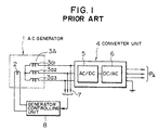
- numeral 1 denotes an A.C. generator driven by an engine (not shown) mounted on an aircraft or the like; 2, a field coil of the A.C. generator; 3A, a three-phase output coils composed of three coils 3a 1 to 3a 3 ; and 4, a converter unit composed of a rectifying circuit 5 and an inverter 6, i.e. the converter unit provided with controlling means of PWM (Pulse Width Modulation) or the like for achieving frequency control.
- PWM Pulse Width Modulation
- the current capacity of the rectifying circuit 5 in the converter unit 4 and the inverter 6 have been set in accordance with the current capacity of the A.C. generator 1.
- Numeral 7 denotes voltage detecting means such as a potential transformer PT, for detecting the voltages at the input terminals of the converter unit 4, and
- numeral 8 denotes a generator controlling unit for controlling the current to be supplied to the field coil 2 of the A.C. generator thereby controlling the output voltage of the generator 1 so as to be constant.
- the converter unit 4 receives a constant voltage e.g. 135 volts from the A.C. generator 1 to rectify it once to D.C. voltage e.g.
- the variation of voltage to be generated due to the variation of an engine power as a drive source is compensated by the generator controlling unit 8, and further the variation of frequency is compensated by the PWM (Pulse Width Modulation) control circuit provided in the inverter 6, and accordingly the load supply electric power P A is controlled to usually maintain a constant voltage and a constant frequency.
- the electric power source used for some devices mounted on such as aircraft, among the various devices, require constant frequency electric power with high precision as 400 H Z , three-phase, 115 V, however most of some other ones merely require a variable frequency but constant voltage source for a heater of a device such as an de-icing device to be heated by the electric power source.
- EP 0057730 discloses an electrical generator which supplies both an A.C. and a D.C. electrical power.
- the AC voltage is controlled by controlling the speed of rotation of a rotary shaft.
- the object of the present invention is to present a constant-frequency electric power source in which the above-mentioned problems of the conventional apparatus are solved.
- a constant-frequency electric power source comprising: an A.C. generator including a field coil to be driven by an engine; a converter unit including a rectifying circuit and an inverter; and means for controlling an output voltage of the A.C. generator; wherein the A.C. generator has at least two groups of multi-phase output coils, one group of said at least two groups of multi-phase output coils being connected to the converter unit for providing a first A.C. electric power with a constant voltage and a constant-frequency to be supplied to a first load, and the remaining groups of the at least two groups of multi-phase output coils being connected to other loads, and further the output of the coils of the remaining group(s) being supplied to the A.C.
- generator voltage controlling means thereby controlling the input of the field coil of the A.C. generator, and the remaining group(s) of said at least two groups of multi-phase output coils further providing a voltage controlled second A.C. electric power used for the other loads being different from the first A.C. electric power used for the first load.
- the turn numbers of coils of each of the remaining groups are suitably set in accordance with the electric power required for each of the other loads.
- the present invention there are provided more than two groups of output coils mounted within an A.C. generator, and one group thereof is connected to the input terminals of a converter unit in order to use for a first load to be supplied with an electric power having a constant-voltage and constant-frequency, and on the other hand the other group thereof is connected to a second load which may be supplied with an A.C. electric power having a variable-frequency and constant-voltage. Therefore, it is possible to precisely adjust the output voltage from the other pair of output coils used for a second load, to a predetermined voltage (e.g. 115 V) under the control of generator controlling means, which resulted from a simple addition of the other group of output coils for the second load. Furthermore, since the electric power to be supplied to the second load is isolated from the converter unit, it is possible to present a preferable wave-form without any distortion.
- a predetermined voltage e.g. 115 V
- the turn numbers of the three-phase output coils 3B used for the second load may be less than that of the three-phase output coils 3A used for the first load by about 30%, and further the turn number of the coils may be suitably set to a predetermined value in accordance with the electric power required for the second load.
- Numeral 11 denotes voltage detecting means such as a potential transformer PT, for detecting the voltage at the input terminals of the second load, and the output from the voltage detecting means 11 is applied to a generator controlling unit (generator controlling means) 8 in order to adjust the current supplied to the field coil 2 of the A.C. generator 10 thereby controlling the electric power P B to to keep a predetermined voltage; e.g.115 V regardless of the variation in number of rotations ie rate of rotation of the engine (not shown).
- a generator controlling unit 8 generator controlling means 8 in order to adjust the current supplied to the field coil 2 of the A.C. generator 10 thereby controlling the electric power P B to to keep a predetermined voltage; e.g.115 V regardless of the variation in number of rotations ie rate of rotation of the engine (not shown).
- the present invention there are provided two or more groups of output coils within an A.C. generator, one group of which is connected to a converter section for supplying an A.C. electric power with a constant-voltage and constant-frequency to a first load, and the other group(s) of which are connected to remaining other loads for supplying an electric power with a variable-frequency and a constant-voltage to the remaining other loads. Therefore, according to the present invention, there is no necessity of providing any transformer which was required for adjusting the voltage supplied to a second load hitherto, and further the weight of an electric power source may be remarkably reduced, because the weight of the pair of output coils additionally provided within the A.C. generator for supplying electric power to the second load is very light in comparison with that of the above transformer. This results in the remarkable merit that the weight of the electric power source to be mounted on an aircraft or the like may be reduced.
- the second load undesirably becomes to a non-linear load for the rectifying circuit 5 of the AC/DC converter of the converter unit, thereby generating a large distortion of wave-form of the electric power to be supplied to the second load and reducing the property of an electric power to be supplied.
- the group of output coils mounted within the A.C. generator for supplying the electric power for the second load is completely insulated from the converter unit thereby not generating any distortion of wave-form and further increasing the characteristic of an electric power to be supplied.
Landscapes
- Engineering & Computer Science (AREA)
- Power Engineering (AREA)
- Control Of Eletrric Generators (AREA)
- Ac-Ac Conversion (AREA)
- Synchronous Machinery (AREA)
Claims (7)
- Elektrische Stromversorgung mit konstanter Frequenz, umfassend:einen Wechselstromgenerator (10) mit einer Feldwicklung (2), der durch einen Motor anzutreiben ist;eine Umrichtereinheit (4) mit einer Gleichrichtschaltung (5) und einem Wechselrichter (6); undMittel (8) zur Steuerung einer Ausgangsspannung des Wechselstromgenerators (10);worin der Wechselstromgenerator (10) zumindest zwei Gruppen von Mehrphasenausgangswicklungen aufweist, wobei eine Gruppe (3A) der zumindest zwei Gruppen von Mehrphasenausgangswicklungen mit der Umrichtereinheit verbunden ist, um eine erste elektrische Wechselstromleistung (PA) mit konstanter Spannung und konstanter Frequenz an eine erste Last zu liefern, und die verbleibende(n) Gruppe(n) (3B) der zumindest zwei Gruppen von Mehrphasenausgangswicklungen mit anderen Lasten verbunden ist bzw. sind, wobei der Ausgang der Wicklungen der verbleibenden Gruppe(n) an das bzw. die Wechselstromgenerator-Spannungssteuerungsmittel (8) geleitet wird, wodurch der Eingang der Feldwicklung (2) des Wechselstromgenerators gesteuert wird, und die verbleibende(n) Gruppe(n) (3B) der zumindest zwei Gruppen von Mehrphasenausgangswicklungen weiters eine spannungsgesteuerte zweite elektrische Wechselstromleistung (PB) liefert bzw. liefern, die für die anderen Lasten verwendet wird und sich von der für die erste Last verwendeten ersten elektrischen Wechselstromleistung (PA) unterscheidet.
- Elektrische Stromversorgung mit konstanter Frequenz nach Anspruch 1, worin die für die anderen Lasten verwendete zweite elektrische Wechselstromleistung (PB) eine variable Frequenz und konstante Spannung aufweist.
- Elektrische Stromversorgung mit konstanter Frequenz nach Anspruch 1, worin die Windungszahl der Wicklung jeder der verbleibenden Gruppen (3B) an Wicklungen passend gemäß der zweiten elektrischen Leistung (PB) eingestellt wird, die für jede der anderen Lasten erforderlich ist.
- Elektrische Stromversorgung mit konstanter Frequenz nach Anspruch 1, worin die verbleibenden Gruppen (3B) von Wicklungen, die innerhalb des Wechselstromgenerators (10) montiert sind, um die zweite elektrische Wechselstromleistung (PB) für die anderen Lasten zu liefern, vollständig von der Umrichtereinheit (4) isoliert sind.
- Elektrische Stromversorgung mit konstanter Frequenz nach Anspruch 1, worin jede Gruppe an Mehrphasenausgangswicklungen Wicklungen von zumindest drei Phasen enthält.
- Elektrische Stromversorgung mit konstanter Frequenz nach Anspruch 5, worin jede Gruppe an Mehrphasenausgangswicklungen Wicklungen von mehr als drei Phasen, wie z.B. sechs Phasen, enthält.
- Elektrische Stromversorgung mit konstanter Frequenz nach einem der vorhergehenden Ansprüche, worin die Gruppen an Mehrphasenausgangswicklungen die gleiche Anzahl an Ausgangswicklungen besitzen.
Applications Claiming Priority (2)
| Application Number | Priority Date | Filing Date | Title |
|---|---|---|---|
| JP4134449A JPH05308799A (ja) | 1992-04-28 | 1992-04-28 | 定周波電源装置 |
| JP134449/92 | 1992-04-28 |
Publications (3)
| Publication Number | Publication Date |
|---|---|
| EP0568262A2 EP0568262A2 (de) | 1993-11-03 |
| EP0568262A3 EP0568262A3 (en) | 1994-06-08 |
| EP0568262B1 true EP0568262B1 (de) | 1996-12-27 |
Family
ID=15128612
Family Applications (1)
| Application Number | Title | Priority Date | Filing Date |
|---|---|---|---|
| EP93303107A Expired - Lifetime EP0568262B1 (de) | 1992-04-28 | 1993-04-21 | Elektrische Stromversorgung mit konstanter Frequenz |
Country Status (3)
| Country | Link |
|---|---|
| US (1) | US5391975A (de) |
| EP (1) | EP0568262B1 (de) |
| JP (1) | JPH05308799A (de) |
Families Citing this family (15)
| Publication number | Priority date | Publication date | Assignee | Title |
|---|---|---|---|---|
| FR2718902B1 (fr) * | 1994-04-13 | 1996-05-24 | Europ Gas Turbines Sa | Ensemble turbine-générateur sans réducteur. |
| US5705917A (en) * | 1994-09-14 | 1998-01-06 | Coleman Powermate, Inc. | Light weight machine with rotor employing permanent magnets and consequence poles |
| US6118186A (en) * | 1994-09-14 | 2000-09-12 | Coleman Powermate, Inc. | Throttle control for small engines and other applications |
| US5929611A (en) * | 1994-09-14 | 1999-07-27 | Coleman Powermate, Inc. | Light weight rotor and stator with multiple coil windings in thermal contact |
| US5764036A (en) * | 1995-03-08 | 1998-06-09 | Sundstrand Corporation | Multiple output decoupled synchronous generator and electrical system employing same |
| KR100860284B1 (ko) * | 2001-02-16 | 2008-09-25 | 얀마 가부시키가이샤 | 엔진에 의해 구동되는 발전기를 갖는 전력 시스템 |
| EP1329672B1 (de) * | 2002-01-17 | 2006-10-11 | Hitachi, Ltd. | Energiekollektorsystem und zugehöriges Betriebsverfahren |
| JP2003284378A (ja) * | 2002-03-20 | 2003-10-03 | Denso Corp | 車両用交流発電電動装置 |
| US6861897B1 (en) * | 2003-08-13 | 2005-03-01 | Honeywell International Inc. | Active filter for multi-phase AC power system |
| GB2440289B (en) * | 2004-01-30 | 2008-09-17 | Ultra Electronics Ltd | Modular aircraft control system and method |
| RU2332772C1 (ru) * | 2007-06-01 | 2008-08-27 | Федеральное государственное образовательное учреждение высшего профессионального образования Кубанский государственный аграрный университет | Синхронный генератор |
| RU2406210C1 (ru) * | 2009-07-17 | 2010-12-10 | Государственное образовательное учреждение высшего профессионального образования "Южно-Российский государственный университет экономики и сервиса" (ГОУ ВПО "ЮРГУЭС") | Генераторная установка транспортного средства |
| US8283942B2 (en) * | 2009-07-27 | 2012-10-09 | International Truck Intellectual Property Company, Llc | Auxiliary power unit diagnostic tool |
| RU2452635C1 (ru) * | 2011-02-14 | 2012-06-10 | Государственное образовательное учреждение высшего профессионального образования "Южно-Российский государственный университет экономики и сервиса" (ГОУ ВПО "ЮРГУЭС") | Генераторная установка транспортного средства |
| CN104213597B (zh) * | 2014-08-26 | 2017-04-26 | 徐州徐工挖掘机械有限公司 | 一种电动液压挖掘机交流变频调速控制系统 |
Citations (1)
| Publication number | Priority date | Publication date | Assignee | Title |
|---|---|---|---|---|
| EP0057730A1 (de) * | 1980-08-19 | 1982-08-18 | Mitsubishi Denki Kabushiki Kaisha | Elektrischer generator |
Family Cites Families (13)
| Publication number | Priority date | Publication date | Assignee | Title |
|---|---|---|---|---|
| JPS50154716A (de) * | 1974-06-03 | 1975-12-13 | ||
| US4262242A (en) * | 1979-09-04 | 1981-04-14 | Sundstrand Corporation | Voltage regulator |
| US4330743A (en) * | 1980-07-17 | 1982-05-18 | Sundstrand Corporation | Electrical aircraft engine start and generating system |
| US4442396A (en) * | 1983-03-31 | 1984-04-10 | Sundstrand Corporation | Generator system with fault condition excitation |
| US4554501A (en) * | 1984-04-27 | 1985-11-19 | Westinghouse Electric Corp. | Variable speed constant frequency power system with auxiliary DC output |
| US4559487A (en) * | 1984-09-07 | 1985-12-17 | Sundstrand Corporation | Voltage regulator with independent peak and average voltage sensing |
| JPS6169399A (ja) * | 1984-09-13 | 1986-04-09 | Shinko Electric Co Ltd | 3相交流定周波数電源装置 |
| US4743777A (en) * | 1986-03-07 | 1988-05-10 | Westinghouse Electric Corp. | Starter generator system with two stator exciter windings |
| CA2005093A1 (en) * | 1988-12-29 | 1990-06-29 | David A. Fox | Circuit and method for voltage regulation of electric power sources |
| US5097195A (en) * | 1989-11-27 | 1992-03-17 | Sundstrand Corporation | AC exciter for VSCF starter/generator |
| US5031086A (en) * | 1989-12-20 | 1991-07-09 | Sundstrand Corporation | Hybrid power system |
| US5055765A (en) * | 1990-09-04 | 1991-10-08 | Sundstrand Corporation | Voltage regulator for direct current aircraft power bus |
| US5225973A (en) * | 1990-09-13 | 1993-07-06 | Sunil Patel | Regulation circuit for a stepped-waveform inverter |
-
1992
- 1992-04-28 JP JP4134449A patent/JPH05308799A/ja active Pending
-
1993
- 1993-04-21 EP EP93303107A patent/EP0568262B1/de not_active Expired - Lifetime
- 1993-04-23 US US08/051,309 patent/US5391975A/en not_active Expired - Fee Related
Patent Citations (1)
| Publication number | Priority date | Publication date | Assignee | Title |
|---|---|---|---|---|
| EP0057730A1 (de) * | 1980-08-19 | 1982-08-18 | Mitsubishi Denki Kabushiki Kaisha | Elektrischer generator |
Also Published As
| Publication number | Publication date |
|---|---|
| JPH05308799A (ja) | 1993-11-19 |
| US5391975A (en) | 1995-02-21 |
| EP0568262A2 (de) | 1993-11-03 |
| EP0568262A3 (en) | 1994-06-08 |
Similar Documents
| Publication | Publication Date | Title |
|---|---|---|
| EP0568262B1 (de) | Elektrische Stromversorgung mit konstanter Frequenz | |
| EP0264135B1 (de) | Leistungsversorgungseinrichtung für Entladungslast | |
| EP1130765B1 (de) | Steuerungssystem für einen Generator zur Erzeugung einer variablen Frequenz | |
| US5073848A (en) | Power distribution system | |
| EP0313366B1 (de) | Geschwindigkeitsveränderliches, frequenzkonstantes Leistungssystem mit Erhöhungswandlerhilfsausgang | |
| US3593078A (en) | Starting and operating control for an ac motor powered by a dc power supply | |
| US5237494A (en) | Frequency inverting apparatus | |
| JPS62500557A (ja) | 改良された過渡応答を有する給電システム | |
| US5479081A (en) | AC motor controller with voltage margin adjustment | |
| KR930000416B1 (ko) | 유도성부하에 전원을 공급하는데 적합한 회로를 위한 제어장치 | |
| KR100423214B1 (ko) | 전압하강장치및이와같은종류의장치를일체로하는단상주전원공급장치로부터공급되는비동기형견인시스템 | |
| EP0376728A2 (de) | Schaltung und Verfahren zur Spannungsregelung von elektrischen Stromquellen | |
| US3991349A (en) | Droop adjustable control apparatus for direct current motor drives | |
| CA2213202A1 (en) | Drive having a three-phase asynchronous motor with slip ring rotor | |
| US5486751A (en) | Electronic trimming voltage regulator | |
| EP0192960B1 (de) | Wechselstrommotor mit Stromfilter | |
| JP3681177B2 (ja) | 自動車における単数または複数の強力な負荷の消費電力を制御するための回路配置 | |
| US11165378B2 (en) | Method for controlling a system for generating electric power for a power distribution network of an aircraft | |
| EP1440501B1 (de) | Motorsteuerungsschaltung und zugehörige vollbrückenschaltanordnung | |
| US5087872A (en) | Circulating load apparatus | |
| JP2639985B2 (ja) | 単相誘導電動機の制御方法 | |
| US6246218B1 (en) | Method and control device for stabilizing a power supply network | |
| US4104537A (en) | Static converter equipment | |
| DE4021008C2 (de) | Umrichteranordnung mit Wechselstromlast | |
| JPS6037483B2 (ja) | 電源装置 |
Legal Events
| Date | Code | Title | Description |
|---|---|---|---|
| PUAI | Public reference made under article 153(3) epc to a published international application that has entered the european phase |
Free format text: ORIGINAL CODE: 0009012 |
|
| AK | Designated contracting states |
Kind code of ref document: A2 Designated state(s): FR GB IT |
|
| PUAL | Search report despatched |
Free format text: ORIGINAL CODE: 0009013 |
|
| AK | Designated contracting states |
Kind code of ref document: A3 Designated state(s): FR GB IT |
|
| 17P | Request for examination filed |
Effective date: 19940811 |
|
| 17Q | First examination report despatched |
Effective date: 19950703 |
|
| GRAG | Despatch of communication of intention to grant |
Free format text: ORIGINAL CODE: EPIDOS AGRA |
|
| GRAH | Despatch of communication of intention to grant a patent |
Free format text: ORIGINAL CODE: EPIDOS IGRA |
|
| GRAH | Despatch of communication of intention to grant a patent |
Free format text: ORIGINAL CODE: EPIDOS IGRA |
|
| GRAA | (expected) grant |
Free format text: ORIGINAL CODE: 0009210 |
|
| AK | Designated contracting states |
Kind code of ref document: B1 Designated state(s): FR GB IT |
|
| ITF | It: translation for a ep patent filed | ||
| ET | Fr: translation filed | ||
| PLBE | No opposition filed within time limit |
Free format text: ORIGINAL CODE: 0009261 |
|
| STAA | Information on the status of an ep patent application or granted ep patent |
Free format text: STATUS: NO OPPOSITION FILED WITHIN TIME LIMIT |
|
| 26N | No opposition filed | ||
| REG | Reference to a national code |
Ref country code: GB Ref legal event code: IF02 |
|
| PGFP | Annual fee paid to national office [announced via postgrant information from national office to epo] |
Ref country code: FR Payment date: 20030408 Year of fee payment: 11 |
|
| PGFP | Annual fee paid to national office [announced via postgrant information from national office to epo] |
Ref country code: GB Payment date: 20030416 Year of fee payment: 11 |
|
| PG25 | Lapsed in a contracting state [announced via postgrant information from national office to epo] |
Ref country code: GB Free format text: LAPSE BECAUSE OF NON-PAYMENT OF DUE FEES Effective date: 20040421 |
|
| GBPC | Gb: european patent ceased through non-payment of renewal fee |
Effective date: 20040421 |
|
| PG25 | Lapsed in a contracting state [announced via postgrant information from national office to epo] |
Ref country code: FR Free format text: LAPSE BECAUSE OF NON-PAYMENT OF DUE FEES Effective date: 20041231 |
|
| REG | Reference to a national code |
Ref country code: FR Ref legal event code: ST |
|
| PG25 | Lapsed in a contracting state [announced via postgrant information from national office to epo] |
Ref country code: IT Free format text: LAPSE BECAUSE OF NON-PAYMENT OF DUE FEES Effective date: 20050421 |