EP0568320A2 - Procédé et appareil pour afficher des images - Google Patents
Procédé et appareil pour afficher des images Download PDFInfo
- Publication number
- EP0568320A2 EP0568320A2 EP93303286A EP93303286A EP0568320A2 EP 0568320 A2 EP0568320 A2 EP 0568320A2 EP 93303286 A EP93303286 A EP 93303286A EP 93303286 A EP93303286 A EP 93303286A EP 0568320 A2 EP0568320 A2 EP 0568320A2
- Authority
- EP
- European Patent Office
- Prior art keywords
- display
- frame
- image
- monitor
- lines
- Prior art date
- Legal status (The legal status is an assumption and is not a legal conclusion. Google has not performed a legal analysis and makes no representation as to the accuracy of the status listed.)
- Granted
Links
- 238000000034 method Methods 0.000 title claims abstract description 14
- 230000000694 effects Effects 0.000 claims description 6
- 238000010894 electron beam technology Methods 0.000 description 3
- 238000012986 modification Methods 0.000 description 3
- 230000004048 modification Effects 0.000 description 3
- 238000006243 chemical reaction Methods 0.000 description 1
- 238000005520 cutting process Methods 0.000 description 1
- 238000010586 diagram Methods 0.000 description 1
- 238000007689 inspection Methods 0.000 description 1
- 238000004519 manufacturing process Methods 0.000 description 1
- 238000003860 storage Methods 0.000 description 1
Images

Classifications
-
- H—ELECTRICITY
- H04—ELECTRIC COMMUNICATION TECHNIQUE
- H04N—PICTORIAL COMMUNICATION, e.g. TELEVISION
- H04N7/00—Television systems
- H04N7/01—Conversion of standards, e.g. involving analogue television standards or digital television standards processed at pixel level
- H04N7/0112—Conversion of standards, e.g. involving analogue television standards or digital television standards processed at pixel level one of the standards corresponding to a cinematograph film standard
Definitions
- the invention relates to a method of and apparatus for displaying images.
- the invention has particular, but not exclusive, application to the display of images captured at one frame rate on a monitor at another frame rate, for example the display at video frame rate of images captured at film frame rate.
- images captured on film can be converted into electrical video signals for storage and modification in an electronic environment. Once converted into electrical signals the images can be edited, combined with other images and/or modified for example by retouching features in the image or adjusting the colour balance of the image.
- Editing work is usually done on a frame-by-frame basis and electronic editing equipment is available which is able to display simultaneously several frames of one or more video clips at respective display areas of the monitor.
- electronic editing equipment is available which is able to display simultaneously several frames of one or more video clips at respective display areas of the monitor.
- a film clip 1 comprises a plurality of film frames F1 to F5.
- a film clip comprises a plurality of image frames captured at a rate of twenty four frames per second.
- the human eye is sensitive to the fundamental frequency at which moving images are displayed and when film is displayed at twenty four frames per second a 24 Hz flicker can be seen in the displayed image.
- film projectors are provided with a double-shuttered arrangement whereby each frame is displayed twice.
- This double-shuttered projection arrangement increases the fundamental frequency of display to 48Hz which is less detectable by the human eye.
- This double shuttered displaying of film is represented in Figure 1 by the clip 2 in which each frame is displayed twice, eg F1 A and F1 B , with the displays F1 A and F1 B being separated by an in-frame blanking period 3 and the display of consecutive frames, eg F1 B and F2 A separated by an inter-frame blanking period 4 corresponding to the frame pull down period of the projector or other display apparatus (not shown).
- a video clip 5 comprising plural video frames V1 to V5.
- the video frames V1 to V5 correspond respectively to the film frames F1 to F5.
- the vertical length of each frame in Figure 1 represents the length of time that the frame is displayed during playback.
- five frames of the video clips correspond to the same period of time as four frames of the film clip 1.
- Video frames are formed from interleaved fields which are displayed at twice the frame rate.
- each video frame is formed from two interleaved fields, one field corresponding to all of the even numbered lines in the frame and the other field corresponding to all of the odd numbered lines in the field.
- the odd and even fields in each frame of video V1 to V5 are represented by the symbols '0' and 'E' in Figure 1.
- One way in which the above problem of different display rates can be overcome is to increase the number of fields used to represent video frames. By increasing the number of fields representing two consecutive video frames from four to five, the time period occupied by the two video frames will equal that of the corresponding two film frames.
- This approach is known as 3:2 pull down and is illustrated by the display scan clip 6 shown in Figure 1 of the accompanying drawings.
- the first two film frames F1 and F2 are displayed as a first display frame 7 comprising an odd field V1 o and an even field V1 E and a second display frame 8 comprising two odd fields V2 o and an even field V2 E .
- the second frame 8 is displayed by outputting first the odd field V2 o then the even field V2 E and then the same odd field V2 o once again.
- odd and even fields making up a frame are interleaved and during the previewing of a clip the monitor alternates between the display of odd and even fields.
- the correct sequence of display of odd and even fields is maintained by reversing the order of display of the two fields comprising the third frame 9.
- the order of the three fields comprising the fourth frame 9a is even-odd-even, the reverse of the sequence of the second frame 8. It will be appreciated that 3:2 pull down therefore requires complex control circuitry to control the order in which fields are delivered to the monitor for display.
- the present invention aims to overcome the above and associated problems by providing a scheme by which video frames corresponding to respective film frames are displayed at a rate corresponding to the display rate of the film frames.
- a method of displaying an image clip comprising a plurality of image frames on an electronic monitor, in which method each frame is provided to the monitor for display separated from the next image frame by an overscan period.
- an apparatus for displaying an image clip comprising a plurality of image frames
- the apparatus comprising a monitor and control means for providing each image frame to the monitor for display separated from the next image frame by an overscan period.
- the invention provides a system for displaying an image clip comprising image frames captured at a first frame rate on a display arranged normally to display images at a second frame rate different to the first frame rate, the system comprising source means for supplying data defining a plurality of lines of pixels representing said image frames to said display, and control means for increasing the number of line synchronising signals supplied to the display between consecutive vertical synchronising signals in order that said image frames are displayed on said display at said first frame rate.
- the invention also provides an image display system for displaying an image sequence on a monitor at a reduced frame rate, the system comprising circuitry for increasing the number of displayed lines forming each displayed frame.
- the invention extends to an image display system in which the frame display rate of a monitor is reduced by increasing the amount of image information for each image frame supplied to the monitor whilst maintaining constant the rate at which said information is supplied.
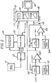
- an editing system 10 comprising a bulk store 11 for storing data representing the frames of plural video clips.
- the bulk store may for example be an array of disc drives among which the video frames are distributed, such as the store disclosed in our co-pending British Patent Application No. 9122215.8, the teachings of which are incorporated herein by reference.
- the data representing the video frames is preferably high resolution data, for example 1125 lines per frame, and the bulk store 11 is able to deliver video frames at display rate (30 frames per second) according to the HDTV standard. Data may be recorded off-line on a VTR for example and downloaded into the bulk store when required.
- the bulk store 11 contains data representing frames of a video clip derived from respective frames of a film clip. That is to say the bulk store 11 at least contains data representing the video clip 5 comprising video frames V1 and V5 as illustrated in Figure 1 of the drawings.
- Data from the bulk store 11 is delivered via a buffer 12 to a framestore 13 and/or to an edit/effects unit 14 which enables for example individual or groups frames to be retouched or otherwise modified and enables two or more video clips to be combined. That is to say, the unit 14 is able to perform editing operations similar to those available in the system manufactured and sold by us under the trade mark "HARRY".
- Pixel data from the framestore 13 are input at display rate to a display driver 15.
- the rate of transfer of pixels from the framestore 13 to the display driver 15 is controlled by a system clock CLK running at display rate, which in the case of HDTV is 54MHz.
- Addressing circuits (not shown) within the framestore 13 ensure that pixels are read from the framestore 13 in raster order.
- the display driver 15 converts the pixel data into an analogue signal which is used to drive a monitor 16 to display thereon the image represented by the data.
- a TV type monitor an image is displayed on a screen by scanning an electron beam over the screen in raster sequence.
- three beams are used to cause red, green and blue components forming a colour image to be displayed on the screen.
- the or each beam is controlled by a video signal which varies continuously the intensity of the beam, a horizontal scan signal which causes the beam to scan horizontally across the screen and to return quickly at the end of one scan line to the beginning of the next, and a vertical scan signal which causes the beam to move to the next scan line and when the bottom of the screen is reached to return quickly to the top of the screen.
- the display driver 15 comprises a digital to analogue converter circuit 17 for converting pixels into a video signal for varying the intensity of the or each electron beam, a horizontal ramping circuit 18 for generating the required horizontal scan signal, and a vertical ramping circuit 19 for generating the required vertical ramp signal.
- the horizontal ramping circuit 18 produces a signal which ramps up from a minimum to a maximum in a period corresponding to that of a single line scan and is reset to the minimum by an external synchronising signal H. Sync..
- the vertical ramping circuit 19 produces a signal which ramps up from a minimum to a maximum in a period corresponding to that of a field scan (ie all 563 odd and 562 even numbered lines in a 1125 line system) and is reset to the minimum by an external synchronising signal V. Sync..
- the system 10 includes circuitry for generating the H. Sync. and V. Sync. signals used to control scanning in the monitor 16.
- a register 21 contains a value corresponding to the number of pixels in each line. For a high definition TV picture of the above mentioned standard each line comprises 1600 pixels and so a value corresponding to that number is held in the register 21.
- the pixel counter 20 and the register 21 are connected to a comparator 22 arranged such that when the contents of the counter and the register are the same, ie the counter has counted to 1600, a pulse is output to a line counter 23 and to a reset input in the pixel counter 20 causing the pixel counter to reset to zero.
- the output from the pixel counter 20 will be directly related to the address of the pixel counter 20 is therefore delivered to the framestore 13 in order to identify the address of the data defining the current pixel to be displayed.
- the output from the comparator 22 corresponds to the abovementioned H.Sync. signal and is input to the display driver 15 causing the horizontal ramping circuit 18 to reset to minimum.
- Each displayed video frame is, of course, made up from interlaced odd and even fields but for the purpose of simplifying the following explanation description will be made of the circuits operation in respect of the odd field only.
- the output from the line counter 23 is also directly related to the address of the pixel in the framestore 13. The count Y from the line counter is therefore delivered to the framestore 13 in order to identify the vertical address of the data defining the current pixel to be displayed.
- a second register 24 contains a value corresponding to the highest numbered line in the field. In a 1125 line system the register 24 would contain a value corresponding to the number 1125.
- the line counter 23 and the second register 24 are coupled to a comparator 25 which outputs a pulse when the count in the line counter 23 matches the value in the register 24.
- the signal from the comparator 25 corresponds to the abovementioned V.Sync. signal and is used to reset the line counter 23 ready to count lines in the next field and to cause the horizontal ramping circuit 19 to reset to a minimum.
- the value in the register 24 is increased by 25%, ie to the value 1409 so that the number of lines counted between V.Sync. pulses is increased.
- the pixel clock rate remains the same (54MHz) and the rate at which lines are scanned also remains unchanged but since the number of lines has increased, the duration of each frame is increased accordingly.
- the vertical ramping circuit 19 is arranged to ramp up to a maximum in a time period corresponding to the full 1125 lines it will remain at the maximum for any further lines thereafter, only resetting when a V. Sync. pulse is received.
- the electron beam of the monitor 16 is caused to scan each line in the field being displayed and then to scan repeatedly the last line until the V.Sync. pulse causes the ramping circuit to reset.
- the system is also arranged so that once all lines of data defining the field have been output from the framestore 13 only null data is output until such time as the line counter is reset to zero.
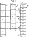
- FIG. 3 the film clip 1 and corresponding video clip 5 are identical to the film and video clips shown in Figure 1.
- video frames V1 to V5 represent respective ones of the film frames F1 to F5.
- V1 o which is the odd field of frame V1
- all pixels are clocked from the framestore 13 at video display rate for display on the monitor.
- null data is output for display until such time as the V.Sync. pulse is generated, thereby identifying the start of a new field.
- the pixels represented by the null data are displayed on the last line of the monitor.
- the contribution that the last line makes to the image is negligible and indeed in most cases the last line is not seen on the display at all.
- the null data supplied to the monitor may therefore have any suitable value for example corresponding to say black pixels where the last line is visible or black or white pixels or even to a part of the image displayed elsewhere on the monitor where the last line cannot be seen on the monitor.
- the system 10 By increasing the number of lines between V. Sync. pulses whilst leaving unchanged the rate of which image pixels are output for display, the system 10 generates a display output comprising odd and even video fields V10, V1 E , V20, V2 E , etc each separated by an overscan period 31.
- the overscan periods 31 correspond approximately to the projection blanking periods 3 and 4 during the display of a film clip as shown in Figure 1.
- video fields are displayed at a rate of forty eight fields per second and thus corresponds to the 48 Hz rate achieved by double-shuttered projection. That is to say, the rate at which the fields DV10, DV1 E , etc. are displayed is reduced to the double-shuttered frame rate of the film 1.
- the flickering is at 48Hz and is in many respects similar to the flicker present in double-shuttered film displays. After a few minutes viewing the viewers eye compensates for any flicker so that the perceived level of flicker is reduced significantly.
Landscapes
- Engineering & Computer Science (AREA)
- Multimedia (AREA)
- Signal Processing (AREA)
- Television Systems (AREA)
Applications Claiming Priority (2)
| Application Number | Priority Date | Filing Date | Title |
|---|---|---|---|
| GB9209204A GB2267008B (en) | 1992-04-29 | 1992-04-29 | A method of and apparatus for displaying images |
| GB9209204 | 1992-04-29 |
Publications (3)
| Publication Number | Publication Date |
|---|---|
| EP0568320A2 true EP0568320A2 (fr) | 1993-11-03 |
| EP0568320A3 EP0568320A3 (fr) | 1994-08-31 |
| EP0568320B1 EP0568320B1 (fr) | 1999-06-16 |
Family
ID=10714705
Family Applications (1)
| Application Number | Title | Priority Date | Filing Date |
|---|---|---|---|
| EP19930303286 Expired - Lifetime EP0568320B1 (fr) | 1992-04-29 | 1993-04-27 | Procédé et appareil pour afficher des images |
Country Status (4)
| Country | Link |
|---|---|
| EP (1) | EP0568320B1 (fr) |
| JP (1) | JP3587539B2 (fr) |
| DE (1) | DE69325311T2 (fr) |
| GB (1) | GB2267008B (fr) |
Families Citing this family (1)
| Publication number | Priority date | Publication date | Assignee | Title |
|---|---|---|---|---|
| US4872937A (en) * | 1988-07-14 | 1989-10-10 | Gte Products Corporation | Electrical component and method of mounting same |
Family Cites Families (2)
| Publication number | Priority date | Publication date | Assignee | Title |
|---|---|---|---|---|
| GB2032216B (en) * | 1978-10-20 | 1982-11-24 | Rank Organisation Ltd | Flying spot continuous motion telecine apparatus having variable line frequency |
| EP0467683A3 (en) * | 1990-07-19 | 1992-09-02 | Canon Kabushiki Kaisha | Image processing apparatus |
-
1992
- 1992-04-29 GB GB9209204A patent/GB2267008B/en not_active Expired - Fee Related
-
1993
- 1993-04-27 EP EP19930303286 patent/EP0568320B1/fr not_active Expired - Lifetime
- 1993-04-27 DE DE1993625311 patent/DE69325311T2/de not_active Expired - Fee Related
- 1993-04-28 JP JP10218393A patent/JP3587539B2/ja not_active Expired - Fee Related
Also Published As
| Publication number | Publication date |
|---|---|
| GB2267008B (en) | 1995-11-01 |
| EP0568320A3 (fr) | 1994-08-31 |
| DE69325311T2 (de) | 1999-10-14 |
| DE69325311D1 (de) | 1999-07-22 |
| JP3587539B2 (ja) | 2004-11-10 |
| GB9209204D0 (en) | 1992-06-17 |
| JPH0630331A (ja) | 1994-02-04 |
| GB2267008A (en) | 1993-11-17 |
| EP0568320B1 (fr) | 1999-06-16 |
Similar Documents
| Publication | Publication Date | Title |
|---|---|---|
| US5418572A (en) | Method of and apparatus for displaying images at different rates | |
| US5191427A (en) | Video post-production of material acquired on film | |
| US5257103A (en) | Method and apparatus for deinterlacing video inputs | |
| US5450129A (en) | Image processing apparatus for converting different television standard signals | |
| JP2573925B2 (ja) | 画像ハ−ドコピ−作成装置 | |
| CN86105117A (zh) | 多画面显示的电视接收机 | |
| ES379714A1 (es) | Perfeccionamientos en sistemas para elaborar informacion pictorica policromada. | |
| US4149191A (en) | Method and system for converting the image content of transported film into television signal picture information | |
| US6895172B2 (en) | Video signal reproducing apparatus | |
| US4752823A (en) | Image recording apparatus for generating a still image from a video signal | |
| US5177615A (en) | Apparatus for recovering a film signal from a television video signal | |
| US5119191A (en) | Flicker processor for cinema video assist | |
| JPS6021513B2 (ja) | 飛点走査式テレシネ装置 | |
| EP0568320B1 (fr) | Procédé et appareil pour afficher des images | |
| US7495704B2 (en) | Method and apparatus for displaying frame rate altered video on interlaced display device | |
| EP0346028B1 (fr) | Appareil d'affichage de signal vidéo | |
| US7623183B2 (en) | Frame rate adjusting method and apparatus for displaying video on interlace display devices | |
| US6392691B1 (en) | Telecine | |
| JPS59138167A (ja) | テレビジヨン信号処理装置 | |
| KR0131458B1 (ko) | 비디오 화상의 재생 화질 개선 방법 및 회로 장치 | |
| US3585292A (en) | Flying spot scanners scanning alternate film frames | |
| JPH0267895A (ja) | 立体映像再生方法および装置 | |
| KR100192949B1 (ko) | 투사형 화상표시시스템의 순차주사변환장치 | |
| KR100221477B1 (ko) | 투사형 화상표시시스템의 파노라마 화면구현장치 | |
| JPH0436510B2 (fr) |
Legal Events
| Date | Code | Title | Description |
|---|---|---|---|
| PUAI | Public reference made under article 153(3) epc to a published international application that has entered the european phase |
Free format text: ORIGINAL CODE: 0009012 |
|
| AK | Designated contracting states |
Kind code of ref document: A2 Designated state(s): DE FR GB IT |
|
| PUAL | Search report despatched |
Free format text: ORIGINAL CODE: 0009013 |
|
| AK | Designated contracting states |
Kind code of ref document: A3 Designated state(s): DE FR GB IT |
|
| 17P | Request for examination filed |
Effective date: 19950127 |
|
| 17Q | First examination report despatched |
Effective date: 19970221 |
|
| GRAG | Despatch of communication of intention to grant |
Free format text: ORIGINAL CODE: EPIDOS AGRA |
|
| GRAG | Despatch of communication of intention to grant |
Free format text: ORIGINAL CODE: EPIDOS AGRA |
|
| GRAG | Despatch of communication of intention to grant |
Free format text: ORIGINAL CODE: EPIDOS AGRA |
|
| GRAH | Despatch of communication of intention to grant a patent |
Free format text: ORIGINAL CODE: EPIDOS IGRA |
|
| GRAH | Despatch of communication of intention to grant a patent |
Free format text: ORIGINAL CODE: EPIDOS IGRA |
|
| GRAA | (expected) grant |
Free format text: ORIGINAL CODE: 0009210 |
|
| AK | Designated contracting states |
Kind code of ref document: B1 Designated state(s): DE FR IT |
|
| REF | Corresponds to: |
Ref document number: 69325311 Country of ref document: DE Date of ref document: 19990722 |
|
| ITF | It: translation for a ep patent filed | ||
| ET | Fr: translation filed | ||
| PLBE | No opposition filed within time limit |
Free format text: ORIGINAL CODE: 0009261 |
|
| STAA | Information on the status of an ep patent application or granted ep patent |
Free format text: STATUS: NO OPPOSITION FILED WITHIN TIME LIMIT |
|
| 26N | No opposition filed | ||
| PGFP | Annual fee paid to national office [announced via postgrant information from national office to epo] |
Ref country code: IT Payment date: 20090421 Year of fee payment: 17 Ref country code: FR Payment date: 20090417 Year of fee payment: 17 Ref country code: DE Payment date: 20090428 Year of fee payment: 17 |
|
| REG | Reference to a national code |
Ref country code: FR Ref legal event code: ST Effective date: 20101230 |
|
| PG25 | Lapsed in a contracting state [announced via postgrant information from national office to epo] |
Ref country code: DE Free format text: LAPSE BECAUSE OF NON-PAYMENT OF DUE FEES Effective date: 20101103 |
|
| PG25 | Lapsed in a contracting state [announced via postgrant information from national office to epo] |
Ref country code: IT Free format text: LAPSE BECAUSE OF NON-PAYMENT OF DUE FEES Effective date: 20100427 |
|
| PG25 | Lapsed in a contracting state [announced via postgrant information from national office to epo] |
Ref country code: FR Free format text: LAPSE BECAUSE OF NON-PAYMENT OF DUE FEES Effective date: 20100430 |