EP0568362B1 - Mikrowellenherd und Verfahren zum Kochen von Speisen - Google Patents
Mikrowellenherd und Verfahren zum Kochen von Speisen Download PDFInfo
- Publication number
- EP0568362B1 EP0568362B1 EP93303346A EP93303346A EP0568362B1 EP 0568362 B1 EP0568362 B1 EP 0568362B1 EP 93303346 A EP93303346 A EP 93303346A EP 93303346 A EP93303346 A EP 93303346A EP 0568362 B1 EP0568362 B1 EP 0568362B1
- Authority
- EP
- European Patent Office
- Prior art keywords
- cavity
- stage
- air
- cooking
- temperature
- Prior art date
- Legal status (The legal status is an assumption and is not a legal conclusion. Google has not performed a legal analysis and makes no representation as to the accuracy of the status listed.)
- Expired - Lifetime
Links
Images

Classifications
-
- H—ELECTRICITY
- H05—ELECTRIC TECHNIQUES NOT OTHERWISE PROVIDED FOR
- H05B—ELECTRIC HEATING; ELECTRIC LIGHT SOURCES NOT OTHERWISE PROVIDED FOR; CIRCUIT ARRANGEMENTS FOR ELECTRIC LIGHT SOURCES, IN GENERAL
- H05B6/00—Heating by electric, magnetic or electromagnetic fields
- H05B6/64—Heating using microwaves
- H05B6/74—Mode transformers or mode stirrers
- H05B6/745—Rotatable stirrers
-
- H—ELECTRICITY
- H05—ELECTRIC TECHNIQUES NOT OTHERWISE PROVIDED FOR
- H05B—ELECTRIC HEATING; ELECTRIC LIGHT SOURCES NOT OTHERWISE PROVIDED FOR; CIRCUIT ARRANGEMENTS FOR ELECTRIC LIGHT SOURCES, IN GENERAL
- H05B6/00—Heating by electric, magnetic or electromagnetic fields
- H05B6/64—Heating using microwaves
- H05B6/642—Cooling of the microwave components and related air circulation systems
-
- H—ELECTRICITY
- H05—ELECTRIC TECHNIQUES NOT OTHERWISE PROVIDED FOR
- H05B—ELECTRIC HEATING; ELECTRIC LIGHT SOURCES NOT OTHERWISE PROVIDED FOR; CIRCUIT ARRANGEMENTS FOR ELECTRIC LIGHT SOURCES, IN GENERAL
- H05B6/00—Heating by electric, magnetic or electromagnetic fields
- H05B6/64—Heating using microwaves
- H05B6/6447—Method of operation or details of the microwave heating apparatus related to the use of detectors or sensors
- H05B6/645—Method of operation or details of the microwave heating apparatus related to the use of detectors or sensors using temperature sensors
-
- H—ELECTRICITY
- H05—ELECTRIC TECHNIQUES NOT OTHERWISE PROVIDED FOR
- H05B—ELECTRIC HEATING; ELECTRIC LIGHT SOURCES NOT OTHERWISE PROVIDED FOR; CIRCUIT ARRANGEMENTS FOR ELECTRIC LIGHT SOURCES, IN GENERAL
- H05B6/00—Heating by electric, magnetic or electromagnetic fields
- H05B6/64—Heating using microwaves
- H05B6/647—Aspects related to microwave heating combined with other heating techniques
- H05B6/6482—Aspects related to microwave heating combined with other heating techniques combined with radiant heating, e.g. infrared heating
Definitions
- This invention relates to microwave ovens and to methods of cooking food.
- GB-A-2212299 discloses a microwave oven comprising an oven cavity to receive food to be cooked, a magnetron for delivering microwave power to the oven cavity, means for admitting to the cavity a flow of air, a timer for timing cooking, a first temperature sensor for sensing the temperature of the air flow as it enters the cavity, a second temperature sensor for sensing the temperature of the air flow as it leaves the cavity, and a microprocessor responsive to the timer and the first and second temperature sensors for controlling the magnetron to influence the duration of the remaining cooking time.
- US-A-4131779 has a similar disclosure.
- Microwave ovens having radiant heating elements are known. Foodstuffs of different size, shape and dielectric loads produce different air temperature characteristics within the oven.
- the invention aims to provide a way of making the operation of such ovens automatic by monitoring air temperatures in the oven and using the monitored air temperatures to govern the operation of a microprocessor which controls cooking time and energisation of the magnetron and the radiant heating elements.
- a method of cooking food in a microwave oven comprising an oven cavity to receive the food, a magnetron for delivering microwave power to the oven cavity, and means for admitting to the cavity a flow of air, wherein the temperature of the air is detected as the air enters the cavity to yield an air inlet temperature and the temperature is detected as the air leaves the cavity to yield an air outlet temperature, monitoring the air inlet and air outlet temperatures in order to influence the duration of the remaining cooking time, characterised by the air admitted to the cavity cooling the magnetron, a radiant heating element delivering radiant power to the oven cavity, detecting the crossover point of the air inlet and air outlet temperatures and utilising the magnitude of the crossover temperature or time to influence the duration of the remaining cooking time and the application of microwave power and radiant power during the remaining cooking time.
- the air inlet temperature and the air outlet temperature will both be at ambient temperature level.
- the air inlet temperature rises more rapidly than the air outlet temperature.
- the temperature of the inlet air is representative of the dielectric load of the foodstuff placed in the oven because the greater the dielectric load of the food item the more microwave energy is absorbed by the load and hence the cooler will the magnetron run, hence lowering the temperature of the inlet air.
- the air outlet temperature is influenced by the air inlet temperature, the dielectric load and the thermal mass of the food item.
- the air outlet temperature begins to rise more rapidly and there will be a point at which the plot of air outlet temperature against time crosses the plot of the air inlet temperature against time. This is the crossover point which is relied upon in the present invention to determine the thermal load and microwave load of the food item, so that the subsequent cooking process can be controlled, both in terms of duration and application of microwave power and radiant power, during the remaining cooking time.
- the complete cooking process preferably comprises three stages, namely a first stage from commencement of cooking to said crossover point, a second stage from the crossover point to the time when the difference between the inlet and outlet temperatures reaches a predetermined value and a third stage from the termination of the second stage to the end of cooking, the microprocessor controlling the duration of the third stage and the energisation of the magnetron and the radiant heating element throughout cooking.
- a microwave oven comprises an oven cavity to receive food to be cooked, a magnetron for delivering microwave power to the oven cavity, means for admitting to the cavity a flow of air, a timer for timing cooking, a first temperature sensor for sensing the temperature of the air flow as it enters the cavity, a second temperature sensor for sensing the temperature of the air flow as it leaves the cavity, a microprocessor responsive to the timer and the first and second temperature sensors for controlling the magnetron to influence the duration of the remaining cooking time, characterised by the air admitted to the cavity cooling the magnetron, a radiant heating element for delivering radiant power to the oven cavity, wherein the microprocessor is operative to detect the crossover point of the air inlet and air outlet temperatures and, in dependence on the magnitude of the crossover temperature or time, to influence the duration of the remaining cooking time and the application of microwave power and radiant power during the remaining cooking time.
- the first temperature sensor is preferably arranged in an inlet aperture in one side wall of the cavity, and the second temperature sensor is arranged in an outlet aperture in the other side wall of the cavity.
- the outlet aperture is positioned nearer the bottom of the cavity than the top thereof, and in a preferred embodiment of the invention, the outlet aperture is at substantially the same level as the turntable, conveniently at the point in the other side wall where the rim of the turntable is closest to the other side wall.
- the radiant heating element is a grill element in the top of the cavity.
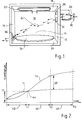
- the oven has a cavity 10 defined by two side walls 12 and 14, a back wall 16, a top wall 18, a base 20 and an openable front door (not shown).
- a radiant grill element 22 is positioned just below the top wall 18 and the base 20 supports a rotatable turntable 24 for supporting a food item to be cooked in the oven.
- the oven has a magnetron 26 which delivers microwave power to the oven cavity 10 through an aperture 28.
- the magnetron 26 is cooled by a cooling fan 30, the flow of air from which enters the cavity 10 through an air inlet aperture 32 in the side wall 12.
- the air flow generally indicated at 34, passes through the cavity 10 and leaves the latter by means of an air outlet aperture 36 formed in the side wall 14.
- the outlet aperture 36 is positioned near the bottom of the cavity and is at substantially the same level as the turntable 24.
- the outlet aperture 36 is positioned in the side wall 14 approximately midway between the front and rear edges thereof, so as to be in that area of the side wall 14 which is closest to the rim of the turntable 24.
- the temperature of the air flow 34 is sensed at two positions: by means of a first thermocouple positioned in the inlet aperture 32 and by a second thermocouple located in the outlet aperture 36.
- the first thermocouple detects air inlet temperature (Ti) and the second thermocouple detects air outlet temperature (To).
- the electrical signals from the two thermocouples are, together with a timer, linked to a microprocessor which controls the operation of the oven.
- Figure 2 shows how Ti and To vary with time in a typical cooking operation.
- Ti and To start from the same temperature, normally ambient temperature.
- Microwave power and radiant power are applied simultaneously to the cavity, as a result of which Ti and To both increase, but initially Ti increases more steeply so that during a first stage of cooking 42 the plot of Ti lies above the plot of To.
- the characteristics of both Ti and To will vary in dependence upon the thermal and microwave load of the food item being cooked so the shapes of the plots of Ti and To during the first stage 42 will be representative of the type of food item being cooked.
- the outlet temperature To begins to increase more steeply than the inlet temperature Ti and there will thus be a crossover (indicated at 44) at which the plots of Ti and To cross.
- the crossover point occurs at time t1 at a temperature T1
- the crossover point 44 defines the end of the first stage 42.
- the magnitude of t1 and/or T1 is sensed by the microprocessor and, in dependence on the value of t1 and/or T1, the microprocessor selects a difference temperature ⁇ T, typically beteween 20°C and 40°C.
- the microprocessor derives ⁇ T by referring to a stored characteristic relating values of t1 to values of ⁇ T.
- the first stage 42 can be regarded as compensating for differing ambient temperatures and differing starting temperatures in the cavity.
- Cooking proceeds through the second stage 46, with the simultaneous and continuous application of microwave power and radiant power and during this second stage the difference between To and Ti is monitored, until this difference reaches the preselected value ⁇ T, which marks the end of the second stage 46.
- ⁇ T the preselected value
- the microprocessor determines the time of a third stage 48 (and hence the time to switch off SO) and also the heating routine, ie the extent and duration of energisation of both the magnetron and the grill element. This is achieved by the microprocessor referring to the stored characteristic of Figure 3, which relates values of the duration of the second stage 46 (ie t2-t1) to values of total cooking time S0. Hence at time t2, the microprocessor computes the duration of the third stage 48, (S0-t2) and the oven displays a remaining cooking time, counting down to zero at switch off at S0.
- microwave power is preferably applied continuously but may be pulsed, if desired.
- Energisation of the grill element 22 during the third stage 48 is governed by the microprocessor in accordance with the stored characteristic of Figure 4 which relates the percentage of the time of the third stage 48 during which the grill element 22 is energised to total cooking time S0.
- the microprocessor having determined the total cooking time S0 from the characteristic of Figure 3, determines the percentage of time of the third stage during which the grill element 22 is energised.
- Energisation of the grill element is intermittent (ie pulsed), there typically being between about three and six pulses or periods of energisation of the grill element 22 during the third stage 48, resulting in the aggregate period of energisation, as a proportion of the total duration of the third stage, corresponding to the percentage derived from the characteristic of Figure 4.
- the invention will have particular application to the cooking of poultry which has a particular cooking requirement in terms of the amount of microwave energy and the amount of radiant energy.
- This balance can be predetermined and programmed into the microprocessor so that once the thermal mass of the poultry item is determined the heating routine is selected and the cooking time to switch off calculated by the microprocessor.
- t1 will be comparatively long
- ⁇ T will be comparatively large
- the duration of the third stage 48 will be comparatively long
- the proportion of the third stage 48 during which the grill element is energised will be comparatively small, to prevent the grill element 22 burning the chicken.
- the grill element 22 being energised for a greater proportion of the third stage because of the smaller risk of burning.
- the turntable 24 may be provided with what is termed a "crisp plate” this is an aluminium circular dish which is placed on the turntable and which is heated from below by a microwave absorbent coating. When the dish carries a large food load it heats up more slowly than when it only has a small load.
- the second thermocouple being situated adjacent to the rim of the crisp plate, is able to detect temperature changes in the crisp plate. This provides an opportunity to control the cooking of essentially flat food items which have high and consistent contact with the crisp plate, such as pizzas.
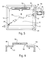
- the oven shown in Figures 5 and 6 (in which parts corresponding to those of Figure 1 bear the same reference numerals) has no turntable, the food being supported on a stationary shelf (not shown) in the oven cavity 10.
- a mode stirrer In the absence of the turntable it is necessary to include a mode stirrer, and in the oven of Figures 5 and 6 this is in the form of a bladed mode stirrer 52 rotatably mounted about a substantially vertical axis.
- the mode stirrer 52 is located in a rectangular box-like extension 53 ( Figure 6) projecting above the top wall 18.
- the mode stirrer 52 is rotatably driven by a stream of air 54. This stream is derived from the output of the fan 30 and is not heated by the magnetron.
- the ovens of Figures 1, 5 and 6 operate in accordance with the preceding description given with reference to Figures 2 to 4. However, it is possible to modify the inventive oven to follow a cooking process having two stages only.
- the first stage corresponds to the stage 42 previously described.
- the microprocessor records the duration of the first stage (ie t1) and, from the magnitude of time t1, derives a total cooking time from a stored characteristic relating t1 to total cooking time. There then follows a second and final cooking stage during which the microwave power and radiant power are applied simultaneously and continuously, until the termination of cooking after the elapse of the derived total cooking time.
Landscapes
- Physics & Mathematics (AREA)
- Electromagnetism (AREA)
- Engineering & Computer Science (AREA)
- Power Engineering (AREA)
- Electric Ovens (AREA)
- Control Of High-Frequency Heating Circuits (AREA)
Claims (10)
- Ein Verfahren zum Kochen von Nahrung in einem Mikrowellenherd mit einem Herdinnenraum (10) zur Aufnahme der Nahrung, einem Magnetron (26) zum Zuführen von Mikrowellenenergie zum Herdinnenraum (10) und mit Mitteln zum Einlassen einer Luftströmung in den Innenraum (10), wobei die Temperatur der Luft bei ihrem Eintritt in den Innenraum (10) zum Erzielen einer Lufteinlaßtemperatur (Ti) und bei ihrem Austritt aus dem Innenraum zum Erzielen einer Luftaustrittstemperatur (To) detektiert wird, und Überwachen der Lufteinlaß- und -auslaßtemperatur zum Beeinflussen der Dauer der verbleibenden Kochzeit, dadurch gekennzeichnet, daß die in den Hohlraum eingelassene Luft das Magnetron kühlt, ein Strahlungsheizelement dem Herdinnenraum (10) Strahlungsenergie zuführt, der Kreuzungspunkt der Lufteinlaß- und -auslaßtemperatur detektiert und die Größe der Temperatur am Kreuzungspunkt (44) oder die Zeit (tl) zum Beeinflussen der Dauer der verbleibenden Kochzeit und Anlegen der Mikrowellen- und der Strahlungsenergie während der verbleibenden Kochzeit verwendet wird.
- Ein Verfahren nach Anspruch 1, wobei der vollständige Kochvorgang drei Stufen umfaßt, nämlich eine erste Stufe (42) vom Beginn des Kochens bis zum Kreuzungspunkt, eine zweite Stufe (46) vom Kreuzungspunkt bis zu der Zeit, bei der der Unterschied zwischen der Einlaß- und der Auslaßtemperatur einen ausgewählten Wert erreicht, abhängig von der Temperatur oder der Zeit am Kreuzungspunkt, und eine dritte Stufe (48) von der Beendigung der zweiten Stufe bis zum Ende des Kochens, und wobei ein Mikroprozessor die Dauer der dritten Stufe (48) und die Erregung des Magnetrons (26) und des Strahlungsheizelementes während des Kochens steuert.
- Ein Verfahren nach Anspruch 2, wobei der Mikroprozessor bei Beendigung der zweiten Stufe (46) die verbleibende Kochzeit durch Bezug auf eine gespeicherte Charakteristik ableitet, die die Zeit der zweiten Stufe zur gesamten Kochzeit in Beziehung setzt.
- Ein Verfahren nach Anspruch 2 oder 3, wobei die Mikrowellen- und die Strahlungsenergie dem Innenraum (10) stetig und gleichzeitig während der ersten und der zweiten Stufe (42, 46) zugeführt werden.
- Ein Verfahren nach Anspruch 4, wobei die Mikrowellenenergie während der dritten Stufe (48) stetig und die Strahlungsenergie während der dritten Stufe (48) intermittierend erzeugt wird, so daß Strahlungsenergieimpulse durchsetzt mit Perioden der Deaktivierung des Strahlungsheizelementes vorgesehen werden, wobei der Anteil der dritten Stufe (48), während dessen die Strahlungsenergie erzeugt wird, unter Bezug auf eine gespeicherte Charakteristik (Fig. 4) abgeleitet wird, die diesen Anteil zu der gesamten Kochzeit in Beziehung setzt.
- Ein Verfahren nach Anspruch 1, wobei der vollständige Kochvorgang zwei Stufen umfaßt, nämlich eine erste Stufe (42) vom Beginn des Kochens bis zum Kreuzungspunkt und eine zweite und abschließende Stufe vom Kreuzungspunkt bis zum Ende des Kochens, und ein Mikroprozessor am Ende der ersten Stufe die verbleibende Kochzeit unter Bezug auf eine gespeicherte Charakteristik ableitet, die die gesamte Kochzeit zu der Dauer der ersten Stufe in Beziehung setzt.
- Ein Mikrowellenherd mit einem Herdinnenraum (10) zur Aufnahme von zu kochender Nahrung, einem Magnetron (26) zum Zuführen von Mikrowellenenergie zum Herdinnenraum (10), mit Mitteln zum Einlassen einer Luftströmung in den Innenraum, mit einem Zeitmesser zum Bemessen der Kochzeit, mit einem ersten Temperatursensor zum Messen der Temperatur (Ti) der Luftströmung bei ihrem Eintreten in den Innenraum (10), mit einem zweiten Temperatursensor zum Messen der Temperatur (To) der Luftströmung bei ihrem Austritt aus dem Innenraum (10) und mit einem auf den Zeitmesser und den ersten und den zweiten Temperatursensor ansprechenden Mikroprozessor zum Steuern des Magnetrons (26) zum Beeinflussen der Dauer der verbleibenden Kochzeit, dadurch gekennzeichnet, daß die in den Innenraum eingelassene Luft das Magnetron kühlt, ein Strahlungsheizelement dem Herdinnenraum Strahlungsenergie zuführt, der Mikroprozessor den Kreuzungspunkt (44) der Lufteinlaß- und -auslaßtemperatur detektiert und in Abhängigkeit von der Größe der Temperatur oder der Zeit am Kreuzungspunkt die Dauer der verbleibenden Kochzeit und des Anwendens der Mikrowellen- und der Strahlungsenergie während der verbleibenden Kochzeit beeinflußt.
- Ein Mikrowellenherd nach Anspruch 7, wobei das Strahlungsheizelement (22) ein an der Oberseite des Innenraums (10) angeordnetes Gitterelement ist.
- Ein Mikrowellenherd nach Anspruch 7 oder 8, wobei zum Halten der Nahrung ein Drehtisch (24) am Boden des Innenraums (10) angeordnet ist.
- Ein Mikrowellenherd nach Anspruch 7 oder 8, wobei der Herd keinen Drehtisch aufweist und einen Betriebspropeller (52) enthält, der von einem von einem Gebläse (30) erzeugten Luftstrom (24) in Drehung versetzt wird, und das Gebläse (30) auch zum Erzeugen eines Luftstroms, der das Magnetron (56) kühlt und in den Innenraum (10) eingelassen wird, dient.
Applications Claiming Priority (2)
| Application Number | Priority Date | Filing Date | Title |
|---|---|---|---|
| GB9209350 | 1992-04-30 | ||
| GB929209350A GB9209350D0 (en) | 1992-04-30 | 1992-04-30 | Microwave ovens and methods of cooking food |
Publications (2)
| Publication Number | Publication Date |
|---|---|
| EP0568362A1 EP0568362A1 (de) | 1993-11-03 |
| EP0568362B1 true EP0568362B1 (de) | 1998-01-14 |
Family
ID=10714795
Family Applications (1)
| Application Number | Title | Priority Date | Filing Date |
|---|---|---|---|
| EP93303346A Expired - Lifetime EP0568362B1 (de) | 1992-04-30 | 1993-04-28 | Mikrowellenherd und Verfahren zum Kochen von Speisen |
Country Status (4)
| Country | Link |
|---|---|
| US (1) | US5302793A (de) |
| EP (1) | EP0568362B1 (de) |
| DE (1) | DE69316259D1 (de) |
| GB (1) | GB9209350D0 (de) |
Families Citing this family (9)
| Publication number | Priority date | Publication date | Assignee | Title |
|---|---|---|---|---|
| SE9401155L (sv) * | 1994-04-07 | 1995-10-08 | Bengt H Hansson | Automatiskt reglersystem för matberedning i varmluftsugnar |
| KR100281702B1 (ko) * | 1997-12-31 | 2001-02-15 | 구자홍 | 전자레인지의 온도보상방법 |
| US6677562B2 (en) * | 2001-03-13 | 2004-01-13 | Matsushita Electric Industrial Co., Ltd. | High-frequency heating apparatus and cooling system for magnetron-driving power supply utilized in the apparatus |
| US6734403B2 (en) | 2001-04-19 | 2004-05-11 | Whirlpool Corporation | Cooking oven incorporating accurate temperature control and method for doing the same |
| WO2011028729A1 (en) | 2009-09-01 | 2011-03-10 | Manitowoc Foodservice Companies, Llc | Method and apparatus for an air inlet in a cooking device |
| JP2013032872A (ja) * | 2011-08-01 | 2013-02-14 | Sharp Corp | 加熱調理器 |
| DE102017202881B3 (de) * | 2017-02-22 | 2018-07-05 | E.G.O. Elektro-Gerätebau GmbH | Verfahren zum Garen von Gargut |
| US11412584B2 (en) | 2017-12-08 | 2022-08-09 | Alkar-Rapidpak, Inc. | Ovens with metallic belts and microwave launch box assemblies for processing food products |
| US12563647B2 (en) | 2021-04-26 | 2026-02-24 | Alkar-Rapidpak, Inc. | Food processing machines with microwave heating systems and microwave suppression systems |
Family Cites Families (7)
| Publication number | Priority date | Publication date | Assignee | Title |
|---|---|---|---|---|
| US4131779A (en) * | 1976-07-07 | 1978-12-26 | Hitachi Heating Appliances Co., Ltd. | High-frequency heating apparatus |
| JPS5780693A (en) * | 1980-11-10 | 1982-05-20 | Matsushita Electric Industrial Co Ltd | High frequency heater |
| DE3205125A1 (de) * | 1982-02-12 | 1983-08-18 | Licentia Gmbh | Mikrowellengeraet |
| GB8417644D0 (en) * | 1984-07-11 | 1984-08-15 | Microwave Ovens Ltd | Microwave ovens |
| EP0187543A3 (de) * | 1985-01-03 | 1988-03-30 | Microwave Ovens Limited | Mikrowellenherd und Verfahren zur Zubereitung von Speisen |
| DE3775091D1 (de) * | 1986-03-26 | 1992-01-23 | Microwave Ovens Ltd | Mikrowellenoefen und verfahren zum kochen von lebensmitteln. |
| KR900003967B1 (ko) * | 1987-12-22 | 1990-06-05 | 주식회사 금성사 | 전자레인지의 자동요리방법 |
-
1992
- 1992-04-30 GB GB929209350A patent/GB9209350D0/en active Pending
-
1993
- 1993-04-27 US US08/053,950 patent/US5302793A/en not_active Expired - Fee Related
- 1993-04-28 DE DE69316259T patent/DE69316259D1/de not_active Expired - Lifetime
- 1993-04-28 EP EP93303346A patent/EP0568362B1/de not_active Expired - Lifetime
Also Published As
| Publication number | Publication date |
|---|---|
| EP0568362A1 (de) | 1993-11-03 |
| US5302793A (en) | 1994-04-12 |
| GB9209350D0 (en) | 1992-06-17 |
| DE69316259D1 (de) | 1998-02-19 |
Similar Documents
| Publication | Publication Date | Title |
|---|---|---|
| US4396817A (en) | Method of browning food in a microwave oven | |
| EP0169000B1 (de) | Mikrowellenherd und Verfahren zum Zubereiten von Speisen | |
| EP0327262B1 (de) | Mikrowellenöfen und Verfahren, um darin Lebensmittel aufzutauen | |
| CA1298623C (en) | Microwave ovens and methods of cooking food | |
| US4841111A (en) | Microwave oven with improved defrosting mode | |
| EP1069806B1 (de) | Abtauen bei einem Mikrowellenofen | |
| US4481394A (en) | Combined microwave oven and grill oven with automated cooking _performance | |
| EP0358344B1 (de) | Mikrowellenöfen | |
| CA1241071A (en) | Microwave oven having low-energy defrost and high- energy cooking modes | |
| CA1249036A (en) | Microwave ovens and methods of cooking food | |
| GB2033108A (en) | Controlling heating apparatus | |
| EP1991813B1 (de) | Kochverfahren für einen kombiofen | |
| US5302793A (en) | Microwave ovens with air inlet and air outlet temperature sensors | |
| GB2137860A (en) | Microwave ovens and methods of cooking food | |
| EP0780641B1 (de) | Kocher | |
| JP2000058227A (ja) | 電気加熱装置の操作方法 | |
| CA1117190A (en) | Method of browning foods in a microwave oven | |
| CA1307561C (en) | Automatic cooking control system for a microwave oven | |
| EP0239290B1 (de) | Mikrowellenöfen und Verfahren zum Kochen von Lebensmitteln | |
| EP0066637B1 (de) | Verfahren zum Aufbräunen von Nahrungsmitteln in einem Mikrowellenherd | |
| JPS56102617A (en) | Heating cooker | |
| US4771152A (en) | Microwave ovens and methods for cooking primarily baked goods and frozen foods | |
| CN109282329B (zh) | 一种电磁灶的控制方法 | |
| EP0083663A1 (de) | Mikrowellenofen | |
| JPH0315922Y2 (de) |
Legal Events
| Date | Code | Title | Description |
|---|---|---|---|
| PUAI | Public reference made under article 153(3) epc to a published international application that has entered the european phase |
Free format text: ORIGINAL CODE: 0009012 |
|
| AK | Designated contracting states |
Kind code of ref document: A1 Designated state(s): DE FR GB IT SE |
|
| 17P | Request for examination filed |
Effective date: 19940309 |
|
| 17Q | First examination report despatched |
Effective date: 19960826 |
|
| GRAG | Despatch of communication of intention to grant |
Free format text: ORIGINAL CODE: EPIDOS AGRA |
|
| GRAH | Despatch of communication of intention to grant a patent |
Free format text: ORIGINAL CODE: EPIDOS IGRA |
|
| GRAH | Despatch of communication of intention to grant a patent |
Free format text: ORIGINAL CODE: EPIDOS IGRA |
|
| GRAA | (expected) grant |
Free format text: ORIGINAL CODE: 0009210 |
|
| AK | Designated contracting states |
Kind code of ref document: B1 Designated state(s): DE FR GB IT SE |
|
| PG25 | Lapsed in a contracting state [announced via postgrant information from national office to epo] |
Ref country code: IT Free format text: LAPSE BECAUSE OF FAILURE TO SUBMIT A TRANSLATION OF THE DESCRIPTION OR TO PAY THE FEE WITHIN THE PRE;WARNING: LAPSES OF ITALIAN PATENTS WITH EFFECTIVE DATE BEFORE 2007 MAY HAVE OCCURRED AT ANY TIME BEFORE 2007. THE CORRECT EFFECTIVE DATE MAY BE DIFFERENT FROM THE ONE RECORDED.SCRIBED TIME-LIMIT Effective date: 19980114 Ref country code: FR Free format text: LAPSE BECAUSE OF FAILURE TO SUBMIT A TRANSLATION OF THE DESCRIPTION OR TO PAY THE FEE WITHIN THE PRESCRIBED TIME-LIMIT Effective date: 19980114 |
|
| REF | Corresponds to: |
Ref document number: 69316259 Country of ref document: DE Date of ref document: 19980219 |
|
| PG25 | Lapsed in a contracting state [announced via postgrant information from national office to epo] |
Ref country code: SE Free format text: LAPSE BECAUSE OF FAILURE TO SUBMIT A TRANSLATION OF THE DESCRIPTION OR TO PAY THE FEE WITHIN THE PRESCRIBED TIME-LIMIT Effective date: 19980414 |
|
| PG25 | Lapsed in a contracting state [announced via postgrant information from national office to epo] |
Ref country code: DE Free format text: LAPSE BECAUSE OF FAILURE TO SUBMIT A TRANSLATION OF THE DESCRIPTION OR TO PAY THE FEE WITHIN THE PRESCRIBED TIME-LIMIT Effective date: 19980415 |
|
| PG25 | Lapsed in a contracting state [announced via postgrant information from national office to epo] |
Ref country code: GB Free format text: LAPSE BECAUSE OF NON-PAYMENT OF DUE FEES Effective date: 19980428 |
|
| EN | Fr: translation not filed | ||
| PLBE | No opposition filed within time limit |
Free format text: ORIGINAL CODE: 0009261 |
|
| STAA | Information on the status of an ep patent application or granted ep patent |
Free format text: STATUS: NO OPPOSITION FILED WITHIN TIME LIMIT |
|
| GBPC | Gb: european patent ceased through non-payment of renewal fee |
Effective date: 19980428 |
|
| 26N | No opposition filed |