EP0568590B1 - Procede de traite - Google Patents
Procede de traite Download PDFInfo
- Publication number
- EP0568590B1 EP0568590B1 EP92903725A EP92903725A EP0568590B1 EP 0568590 B1 EP0568590 B1 EP 0568590B1 EP 92903725 A EP92903725 A EP 92903725A EP 92903725 A EP92903725 A EP 92903725A EP 0568590 B1 EP0568590 B1 EP 0568590B1
- Authority
- EP
- European Patent Office
- Prior art keywords
- period
- during
- pressure
- flow
- milking
- Prior art date
- Legal status (The legal status is an assumption and is not a legal conclusion. Google has not performed a legal analysis and makes no representation as to the accuracy of the status listed.)
- Expired - Lifetime
Links
- 238000000034 method Methods 0.000 title claims abstract description 12
- 230000010349 pulsation Effects 0.000 claims abstract description 41
- 239000008267 milk Substances 0.000 claims abstract description 38
- 210000004080 milk Anatomy 0.000 claims abstract description 38
- 235000013336 milk Nutrition 0.000 claims abstract description 38
- 230000003247 decreasing effect Effects 0.000 claims description 21
- 230000007423 decrease Effects 0.000 claims description 10
- 210000002445 nipple Anatomy 0.000 description 69
- 238000009825 accumulation Methods 0.000 description 7
- 210000000481 breast Anatomy 0.000 description 5
- 230000009193 crawling Effects 0.000 description 4
- 230000002035 prolonged effect Effects 0.000 description 4
- 101150038956 cup-4 gene Proteins 0.000 description 3
- 230000003797 telogen phase Effects 0.000 description 3
- 230000000638 stimulation Effects 0.000 description 2
- 125000004122 cyclic group Chemical group 0.000 description 1
- 230000006378 damage Effects 0.000 description 1
- 238000000605 extraction Methods 0.000 description 1
- 238000011084 recovery Methods 0.000 description 1
Images

Classifications
-
- A—HUMAN NECESSITIES
- A01—AGRICULTURE; FORESTRY; ANIMAL HUSBANDRY; HUNTING; TRAPPING; FISHING
- A01J—MANUFACTURE OF DAIRY PRODUCTS
- A01J5/00—Milking machines or devices
- A01J5/007—Monitoring milking processes; Control or regulation of milking machines
Definitions
- the present invention relates to a method of milking an animal by using a milking machine having at least one teat cup with a teat cup liner therein for receiving a teat of the animal, a pulsation chamber being defined between the teat cup and the teat cup liner.
- Each pulsation of said pulsating pressure includes a pressure decreasing phase, during which the pulsating pressure decreases from said first pressure to said second pressure, and a pressure increasing phase, during which the pulsating pressure increases from said second pressure to said first pressure.
- Means are provided for subjecting the interior of the teat cup liner to said sub-atmospheric second pressure for extracting milk from the animal's teat.
- the milking of the animal includes in sequence an initial massage period, during which the milk flow begins, a main flow period, during which the milk flow first increases to a main flow and then continues at said main flow, a flow decreasing period, during which the milk flow at first for a short while amounts to said main flow and then decreases, and a flow terminating period, during which the milk flow ceases.
- the object of the present invention is to provide a method of milking, which enables a relatively rapid milk extraction, reduces the rest milk and results in a gentle treatment of the cow's teats.
- This object can be obtained by means of a method of the kind initially stated, which is characterized by operating the milking machine to change the pulsating pressure during at least one of said pressure decreasing phase and said pressure increasing phase of each pulsation at a slower rate during at least one of said massage period, flow decreasing period and flow terminating period than during said main flow period.
- the teat cup liner will move slower during opening and/or closing of the interior of the teat cup liner during any of said periods of the milking.
- a slower opening of the interior of the teat cup liner means that the teat has more time to expand radially and maintains its frictional engagement with the teat cup liner, whereby the teat cup is prevented from crawling upwards on the teat towards the udder and from causing a throttling of the milk conducting interior of the teat close to the udder.
- Such a crawling of the teat cup makes the milking more difficult and gives rise to increased rest milk.
- a slower closing of the interior of the teat cup liner means that the teat is treated more gently by the teat cup liner.
- the pulsating pressure in the pulsation chamber changes at a normal rate, which means that the total milking still can be carried out relatively rapidly.
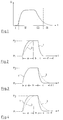
- figure 1 is a graph, which illustrates the size of the milk flow during a milking operation
- figures 2-4 are three graphs illustrating the cyclic course of the pressure in a pulsation chamber according to three alternative milking operations according to the invention
- figures 5-7 schematically show three alternative milking machines for accomplishing the milking method according to the invention.
- FIG. 1 In the graph according to figure 1 there is shown a typical relation between milk flow Q and time t during milking of a cow.
- an initial massage period I the teats of the cow are stimulated, so that the milk yield begins.
- a main period II follows, during which the milk flow increases to a main flow, and then stays relatively constant for a substantial part of the main period II.
- a milk flow decreasing period III follows, during which the milk flow for a first short time amounts to the main flow and then steadily decreases.
- a milk flow terminating period IV occurs, during which the milk flow ceases.
- a continuous line 1 how the pulsating pressure in a pulsation chamber of a teat cup provided with a teat cup liner varies between a high pressure P 1 and a low pressure P 2 during a pulsation cycle.
- an opening phase a see figure 3
- the pulsating pressure is decreased from the value P 1 to the value P 2 , which results in that the interior of the teat cup liner is opened and milk can flow from the teat.
- a following milking phase b see figure 2 the pulsating pressure is kept at the value P 2 , the interior of the teat cup liner being kept open.
- a closing phase c follows, during which the pulsating pressure according to the line 1 is increased from the value P 2 to the value P 1 , which results in that the interior of the teat cup liner is closed and milk is prevented from flowing from the teat.
- the pulsating pressure is kept at the value P 1 , the interior of the teat cup liner being kept closed.
- a pulsation cycle comprising the phases a-d usually lasts between 0.7 to 1.5 seconds.
- the milking machine shown in figure 5 comprises a teat cup 4 with a teat cup liner 5, a pulsation chamber 6 being defined between the teat cup 4 and the teat cup liner 5.
- a milk passage 7 leads to a receptacle 8, the interior of which is subjected to a sub-atmospheric low pressure P 2 by a low pressure source 9 via a low pressure passage 10.
- a pulsator 11 is connected to the pulsation chamber 6 via a pulsation passage 12, to the low pressure source 9 via a low pressure passage 13, and to a high pressure source 14, which generates a high pressure P 1 , via a high pressure passage 15.
- the passages 12, 13 and 15 are provided with controllable valves 16, 17 and 18, respectively.
- a control unit 19 is connected to the valves 16, 17 and 18 for controlling these.
- the milking machine according to figure 5 is operated in the following way.
- the low pressure source 9 subjects the interior of the teat cup liner 5 to the low pressure P 2 via the passage 10, the interior of the receptacle 8 and the passage 7, while the pulsator alternately subjects the pulsation chamber 6 to the high pressure P 1 from the high pressure source 14 via the passages 15 and 12, and to the low pressure P 2 from the low pressure source 9 via the passages 13 and 12.
- both the opening rate and the closing rate of the teat cup liner can be reduced by throttling the pulsation channel 12 by means of the valve 16 (fig 4).
- the opening rate of the teat cup liner 5 may be reduced by throttling the low pressure passage 13 by means of the valve 17 (fig 2), or the closing rate of the teat cup liner 5 may be reduced by throttling the high pressure passage 15 by means of the valve 18 (fig 3).
- One of the opening rate and closing rate of the teat cup liner can optionally be reduced during any of the massage period I, the flow decreasing period III and the flow terminating period IV.
- both the opening rate and the closing rate of the teat cup liner can be reduced during all of these periods, which gives the best protection against teat cup crawling, the most gentle teat treatment and a small amount of rest milk, but a prolonged milking, since the milking phase b and the rest phase d (the recovery phase of the teat) will be shortened during said periods.
- the duration of the rest phase d can be kept normal by only reducing the opening rate of the teat cup liner 5, which shortens the milking time somewhat, but gives a somewhat worse teat treatment.
- the milking machine according to figure 6 differs from the milking machine according to figure 5 in that the control unit 19 only is connected to a valve 20, which is arranged in a connection passage 21 A between the high pressure source 14 and the low pressure passage 13, and to a valve 20 A, which is arranged in a connection passage 21 between the low pressure source 9 and the high pressure passage 15.
- a small leakage from the high pressure source 14 to the low pressure passage 13 via the connection passage 21 A can be provided, so that the pressurization of the pulsation space 6 of the low pressure source 9 takes place at a slower rate, whereby the interior of the teat cup liner 5 is opened at a slower rate.
- a small leakage from the high pressure passage 15 to the low pressure source 9 may be provided by means of the control unit 19 and the valve 20 A, so that the pressurization of the pulsation space 6 by the high pressure source 14 takes place at a slower rate, whereby the interior of the teat cup liner 5 is closed at a slower rate.
- the milking machine according to figure 7 differs from the milking machine according to figure 5 in that an accumulation chamber 22 is connected to the pulsation passage 12 via a passage 23, which is provided with a valve 24, and in that an accumulation chamber 25 is connected to the high pressure passage 15 via a passage 26, which is provided with a valve 27, and to the low pressure passage 13 via a passage 28, which is provided with a valve 29, the control unit 19 being connected to the valves 24, 27 and 29.
- the control unit 19 opens the valve 24 during milking, also the accumulation chamber 22 will be alternately pressurized by the pressure sources 9 and 14, which results in that a corresponding pressurization of the pulsation chamber 6 takes place at slower rate, so that the opening and closing rates of the teat cup liner 5 are reduced.
- control unit 19 controls the valves 27 and 29 during each pulsation cycle, so that during the a-phase the valve 27 is closed while the valve 29 is opened, the accumulation chamber 25 communicating with the low pressure passage 13.
- the control unit 19 closes the valve 29 and then opens the valve 27, so that the accumulation chamber 25 is pressurized by the high pressure source 14.
- the d-phase begins the valve 27 is closed, after which the above described operation is repeated during the next pulsation cycle.
- control unit 19 controls the valves 27 and 29 during each pulsation cycle, so that during the c-phase the valve 29 is closed hile the valve 27 is opened, the accumulation chamber 25 communicating with the high pressure passage 15.
- the control unit 19 closes the valve 27 and then opens the valve 29, so that the accumulation chamber 25 is pressurized by the low pressure source 9.
- the b-phase begins the valve 29 is closed, after which the above described operation is repeated during the next pulsation cycle.
- the high pressure source 14 in the milking machine according to figures 5-7 is suitably constituted by atmospheric pressure.
Landscapes
- Life Sciences & Earth Sciences (AREA)
- Animal Husbandry (AREA)
- Environmental Sciences (AREA)
- External Artificial Organs (AREA)
Abstract
Claims (5)
- Procédé pour traire un animal en utilisant une trayeuse comportant au moins un gobelet trayeur (4) comportant au moins une étui (5) logé dans ce gobelet trayeur pour recevoir le trayon de l'animal, une chambre de pulsation (6) étant définie entre le gobelet trayeur et son étui, des moyens (9,11-15) pour soumettre la chambre de pulsation à une pression pulsatoire variant entre une première pression et une seconde pression sous-atmosphérique, inférieure à ladite première pression, chaque pulsation de ladite pression pulsatoire comprenant une phase de réduction de pression (a) pendant laquelle la pression pulsatoire diminue depuis ladite première pression jusqu'à ladite seconde pression, et une phase d'accroissement de pression (c) pendant laquelle la pression pulsatoire augmente de ladite seconde pression jusqu'à ladite première pression, des moyens (7-10) pour soumettre l'intérieur de l'étui du gobelet trayeur à ladite seconde pression sous-atmosphérique pour extraire du lait à partir du trayon de l'animal, la traite de l'animal incluant successivement une période initiale de massage (i) pendant laquelle l'écoulement (Q) du lait commence, une période d'écoulement principal (II) pendant laquelle l'écoulement de lait commence tout d'abord à augmenter jusqu'à un écoulement principal, puis se poursuit au niveau dudit écoulement principal, une période de réduction de l'écoulement (III) pendant laquelle l'écoulement de lait tout d'abord augmente rapidement pour atteindre ledit écoulement principal, puis diminue, et une période d'achèvement de l'écoulement (IV) pendant laquelle l'écoulement du lait cesse, caractérisé en ce qu'on fait fonctionner la machine à traire de manière à modifier la pression pulsatoire pendant au moins l'une desdites phases comprenant au moins ladite phase de réduction de pression (a) et ladite phase d'augmentation de pression (c) de chaque pulsation, à une cadence plus lente pendant au moins l'une desdites périodes comprenant ladite période de massage (I), ladite période de réduction de l'écoulement (III) et ladite période d'achèvement de l'écoulement (IV), que pendant ladite période d'écoulement principal (II).
- Procédé de traite selon la revendication 1, caractérisé en ce qu'on fait fonctionner la machine à traire de manière à réduire la pression pulsatoire pendant ladite phase de réduction de pression (a) de chaque pulsation à une cadence plus lente pendant la période de massage (I), la période de réduction de l'écoulement (III) et la période d'achèvement de l'écoulement (IV), que pendant la période d'écoulement principal (II).
- Procédé de traite selon la revendication 2, caractérisé en ce qu'on fait fonctionner la machine à traire pour augmenter la pression pulsatoire pendant ladite phase d'augmentation de pression (c) de chaque pulsation à une cadence plus faible pendant la période de massage (I), pendant la période de réduction de l'écoulement (III) et pendant la période d'achèvement de l'écoulement (IV), que pendant la période d'écoulement principal (II).
- Procédé de traite selon la revendication 1, caractérisé en ce qu'on fait fonctionner la machine à traire pour modifier la pression pulsatoire pendant chaque pulsation à une cadence plus faible pendant la période de réduction de l'écoulement (III) que pendant la période de massage (I), pendant la période d'écoulement principal (II) et pendant la période d'achèvement de l'écoulement (IV).
- Procédé de traite selon la revendication 1, caractérisé en ce qu'on fait fonctionner la machine à traire de manière à réduire la pression pulsatoire pendant ladite phase de réduction de pression (a) de chaque impulsion à une cadence plus faible pendant la période de réduction de l'écoulement (III) et pendant la période d'achèvement de l'écoulement (IV), que pendant la période d'écoulement principal (II) et pendant la période de massage (I) et de manière à augmenter la pression pulsatoire pendant ladite phase d'augmentation de pression (c) de chaque pulsation, à une cadence plus faible pendant la période de massage (I), pendant la période de réduction de l'écoulement (III) et pendant la période d'achèvement de l'écoulement (IV) que pendant la période d'écoulement principal (II).
Applications Claiming Priority (3)
| Application Number | Priority Date | Filing Date | Title |
|---|---|---|---|
| SE9100242A SE9100242D0 (sv) | 1991-01-25 | 1991-01-25 | Saett att mjoelka |
| SE9100242 | 1991-01-25 | ||
| PCT/SE1992/000021 WO1992012625A1 (fr) | 1991-01-25 | 1992-01-15 | Procede de traite |
Publications (2)
| Publication Number | Publication Date |
|---|---|
| EP0568590A1 EP0568590A1 (fr) | 1993-11-10 |
| EP0568590B1 true EP0568590B1 (fr) | 1997-03-19 |
Family
ID=20381723
Family Applications (1)
| Application Number | Title | Priority Date | Filing Date |
|---|---|---|---|
| EP92903725A Expired - Lifetime EP0568590B1 (fr) | 1991-01-25 | 1992-01-15 | Procede de traite |
Country Status (7)
| Country | Link |
|---|---|
| US (1) | US5443035A (fr) |
| EP (1) | EP0568590B1 (fr) |
| DE (1) | DE69218409T2 (fr) |
| DK (1) | DK0568590T3 (fr) |
| ES (1) | ES2101835T3 (fr) |
| SE (1) | SE9100242D0 (fr) |
| WO (1) | WO1992012625A1 (fr) |
Cited By (1)
| Publication number | Priority date | Publication date | Assignee | Title |
|---|---|---|---|---|
| US8567345B2 (en) | 2003-06-06 | 2013-10-29 | Gea Farm Technologies Gmbh | Method and device for milking an animal |
Families Citing this family (25)
| Publication number | Priority date | Publication date | Assignee | Title |
|---|---|---|---|---|
| IT1270881B (it) * | 1993-10-01 | 1997-05-13 | S El Pro Di Visigalli Ercolino | Mungitrice automatica |
| SE9304335D0 (sv) * | 1993-12-30 | 1993-12-30 | Alfa Laval Agri Ab | Ventilanordning |
| DE4406741C2 (de) * | 1994-03-02 | 1996-08-29 | Westfalia Separator Ag | Verfahren zum maschinellen Milchentzug |
| SE9401685D0 (sv) * | 1994-05-17 | 1994-05-17 | Tetra Laval Holdings & Finance | Metod för mjölkning av djur |
| SE9401684D0 (sv) * | 1994-05-17 | 1994-05-17 | Tetra Laval Holdings & Finance | Metod för mjölkning av djur |
| SE504429C2 (sv) * | 1995-05-17 | 1997-02-10 | Tetra Laval Holdings & Finance | Sätt att styra mjölkning med hjälp av spengummits abrupta rörelse jämte mjölkningsmaskin med avkännare härför |
| SE504427C2 (sv) * | 1995-05-17 | 1997-02-10 | Tetra Laval Holdings & Finance | Sätt och anordning att mjölka ett djur genom bestämning av pulseringsvakuumets nivå när spengummit öppnar eller stänger abrupt |
| SE511014C2 (sv) * | 1995-12-22 | 1999-07-19 | Alfa Laval Agri Ab | Sätt att mjölka ett djur med hjälp av två olika tryck och mjölkningsmaskin med två tryckkällor |
| DE19614377A1 (de) * | 1996-04-11 | 1997-10-16 | Laub Maier Maria | Verfahren zum maschinellen Milchentzug |
| US6510812B1 (en) * | 1998-05-04 | 2003-01-28 | Delaval Holding Ab | Method and a device for milking an animal |
| DE19926957A1 (de) * | 1999-06-14 | 2001-01-04 | Westfalia Landtechnik Gmbh | Verfahren zum maschinellen Melken von Tieren, insbesondere von Kühen |
| US20030111017A1 (en) * | 2001-12-13 | 2003-06-19 | Wartenhorst Bernhard Schulze | Mechanical milking procedure for animals, especially cows |
| DE10046038A1 (de) * | 2000-09-18 | 2002-04-04 | Westfalia Landtechnik Gmbh | Verfahren zum maschinellen Melken eines Tieres |
| US6990924B2 (en) * | 2003-02-07 | 2006-01-31 | Global Tech Systems Inc | Controller for monitoring and controlling pulsators in a milking system |
| US7841296B2 (en) | 2003-02-07 | 2010-11-30 | Global Tech Systems, Inc. | Controller for monitoring and controlling pulsators in a milking system |
| US7051673B2 (en) * | 2003-02-07 | 2006-05-30 | Global Tech Systems, Inc. | Pulsator controller for monitoring and controlling a designated pulsator in a milking system and method of using same |
| DE102004059572A1 (de) * | 2004-12-09 | 2006-06-22 | Westfaliasurge Gmbh | Verfahren zum Melken eines Tieres |
| US20060198868A1 (en) * | 2005-01-05 | 2006-09-07 | Dewitt David M | Biodegradable coating compositions comprising blends |
| WO2007060003A1 (fr) | 2005-11-25 | 2007-05-31 | Westfaliasurge Gmbh | Procede et dispositif de traite d'animaux |
| NZ570296A (en) * | 2007-09-07 | 2009-08-28 | Delaval Holding Ab | Method and arrangement for controlling the milking by a milking machine |
| US7975647B2 (en) * | 2007-09-22 | 2011-07-12 | Lauren Agrisystems, Ltd. | Flow restrictor for milking apparatus |
| CH701646B1 (de) * | 2007-10-05 | 2011-02-28 | Alfred Kummer | Pulsatorvorrichtung. |
| NZ586308A (en) * | 2008-01-24 | 2012-12-21 | Delaval Holding Ab | Method for controlling milking where milking vacuum and maximum pulsation vacuum are lowered during a termination phase |
| US20210289737A1 (en) * | 2020-03-17 | 2021-09-23 | Lanny Gehm | Pulsator |
| JP2024532126A (ja) | 2021-08-30 | 2024-09-05 | デラバル ホールディング アクチエボラグ | 搾乳システム |
Family Cites Families (11)
| Publication number | Priority date | Publication date | Assignee | Title |
|---|---|---|---|---|
| US2039421A (en) * | 1932-11-26 | 1936-05-05 | Laval Separator Co De | Process and apparatus for milking |
| DE2057100A1 (de) * | 1970-11-20 | 1972-05-31 | Bizerba-Werke Wilhelm Kraut KG, 7460 Baiingen | Verfahren zum Melken von Tieren |
| GB1450169A (en) * | 1973-09-14 | 1976-09-22 | Phillips E M | Method of milking |
| SE382547B (sv) * | 1974-06-14 | 1976-02-09 | Alfa Laval Ab | Sett vid drift av en mjolkningsmaskin samt arrangemang herfor |
| SE408945B (sv) * | 1977-12-06 | 1979-07-16 | Alfa Laval Ab | Pneumatisk fordrojningsanordning |
| DE2844562C2 (de) * | 1978-10-12 | 1983-01-05 | Bio-Melktechnik Swiss Hoefelmayr & Co, 9052 Niederteufen, Aargau | Verfahren zum selbsttätigen Ausmelken beim maschinellen Milchentzug |
| DD141770A2 (de) * | 1978-11-29 | 1980-05-21 | Volkmar Spillecke | Ueberstroemsperre fuer wechseltakt-membranpulsator mit phasenverschiebung |
| DE3047579C2 (de) * | 1980-12-17 | 1986-01-30 | Biomelktechnik Swiss Hoefelmayr & Co, Niederteufen, Appenzell Außerrhoden | Verfahren und Vorrichtung zum maschinellen Milchentzug |
| DK152321C (da) * | 1980-01-21 | 1988-07-11 | Hoefelmayr Bio Melktech | Fremgangsmaade og apparat til maskinel udmalkning |
| SU1334112A1 (ru) * | 1983-04-21 | 1987-08-30 | Институт Технической Кибернетики Ан Бсср | Система управлени доильным аппаратом |
| US5218924A (en) * | 1992-03-19 | 1993-06-15 | Dec International, Inc. | Milking system with variable pressure source |
-
1991
- 1991-01-25 SE SE9100242A patent/SE9100242D0/xx unknown
-
1992
- 1992-01-15 DK DK92903725.7T patent/DK0568590T3/da active
- 1992-01-15 EP EP92903725A patent/EP0568590B1/fr not_active Expired - Lifetime
- 1992-01-15 WO PCT/SE1992/000021 patent/WO1992012625A1/fr not_active Ceased
- 1992-01-15 DE DE69218409T patent/DE69218409T2/de not_active Expired - Fee Related
- 1992-01-15 ES ES92903725T patent/ES2101835T3/es not_active Expired - Lifetime
- 1992-01-15 US US08/090,149 patent/US5443035A/en not_active Expired - Lifetime
Cited By (1)
| Publication number | Priority date | Publication date | Assignee | Title |
|---|---|---|---|---|
| US8567345B2 (en) | 2003-06-06 | 2013-10-29 | Gea Farm Technologies Gmbh | Method and device for milking an animal |
Also Published As
| Publication number | Publication date |
|---|---|
| WO1992012625A1 (fr) | 1992-08-06 |
| DE69218409T2 (de) | 1997-07-10 |
| SE9100242D0 (sv) | 1991-01-25 |
| US5443035A (en) | 1995-08-22 |
| EP0568590A1 (fr) | 1993-11-10 |
| DK0568590T3 (da) | 1997-04-14 |
| DE69218409D1 (de) | 1997-04-24 |
| ES2101835T3 (es) | 1997-07-16 |
Similar Documents
| Publication | Publication Date | Title |
|---|---|---|
| US5443035A (en) | Method of milking | |
| US4011838A (en) | Electronic milker | |
| CA1160589A (fr) | Methode de traite mecanique | |
| US5992347A (en) | Method of milking and a milking machine | |
| US4292926A (en) | Method for the automatic finish milking during a mechanical milk removal procedure | |
| US8240272B2 (en) | Milking equipment | |
| EP2252142B1 (fr) | Procédé pour le contrôle de traite par une machine à traire | |
| EP0403549B1 (fr) | Machine a traire et methode de traite utilisant cette machine | |
| CA2270456A1 (fr) | Methode et outil pour la traite automatique des animaux | |
| US6651583B1 (en) | Method and a device for milking an animal | |
| US9326481B2 (en) | Method and apparatus for milking animals | |
| CA2381071C (fr) | Dispositif de traite automatique d'animaux | |
| US5697323A (en) | Method and machine for milking | |
| CA2265747A1 (fr) | Structure contenant une machine a traire, et procede associe | |
| US6170434B1 (en) | Method of and an implement for milking and/or treating animals | |
| CN116634862B (zh) | 乳汁提取系统和计算机实施的方法 | |
| SU392916A1 (ru) | Манипулятор доения | |
| SU1509004A1 (ru) | Переключающее устройство дл получени различных пульсационных вакуумов в межстенном пространстве доильного стакана и различных чисел тактов на фазе доени и стимулировани | |
| GB2078077A (en) | Method of and apparatus for milking | |
| WO1999034664A1 (fr) | Dispositif de manchon trayeur | |
| GB1592408A (en) | Method and apparatus for milking | |
| CA2184605A1 (fr) | Procede de traite mecanique | |
| WO1984000874A1 (fr) | Trayeuse mecanique | |
| AU1941083A (en) | Milking machine |
Legal Events
| Date | Code | Title | Description |
|---|---|---|---|
| PUAI | Public reference made under article 153(3) epc to a published international application that has entered the european phase |
Free format text: ORIGINAL CODE: 0009012 |
|
| 17P | Request for examination filed |
Effective date: 19930724 |
|
| AK | Designated contracting states |
Kind code of ref document: A1 Designated state(s): DE DK ES FR GB NL SE |
|
| 17Q | First examination report despatched |
Effective date: 19950516 |
|
| GRAG | Despatch of communication of intention to grant |
Free format text: ORIGINAL CODE: EPIDOS AGRA |
|
| GRAH | Despatch of communication of intention to grant a patent |
Free format text: ORIGINAL CODE: EPIDOS IGRA |
|
| GRAH | Despatch of communication of intention to grant a patent |
Free format text: ORIGINAL CODE: EPIDOS IGRA |
|
| GRAA | (expected) grant |
Free format text: ORIGINAL CODE: 0009210 |
|
| AK | Designated contracting states |
Kind code of ref document: B1 Designated state(s): DE DK ES FR GB NL SE |
|
| REG | Reference to a national code |
Ref country code: DK Ref legal event code: T3 |
|
| REF | Corresponds to: |
Ref document number: 69218409 Country of ref document: DE Date of ref document: 19970424 |
|
| ET | Fr: translation filed | ||
| REG | Reference to a national code |
Ref country code: ES Ref legal event code: FG2A Ref document number: 2101835 Country of ref document: ES Kind code of ref document: T3 |
|
| PLBE | No opposition filed within time limit |
Free format text: ORIGINAL CODE: 0009261 |
|
| STAA | Information on the status of an ep patent application or granted ep patent |
Free format text: STATUS: NO OPPOSITION FILED WITHIN TIME LIMIT |
|
| 26N | No opposition filed | ||
| REG | Reference to a national code |
Ref country code: GB Ref legal event code: IF02 |
|
| REG | Reference to a national code |
Ref country code: GB Ref legal event code: 732E |
|
| REG | Reference to a national code |
Ref country code: FR Ref legal event code: TP |
|
| NLS | Nl: assignments of ep-patents |
Owner name: DE LAVAL HOLDING AB |
|
| PGFP | Annual fee paid to national office [announced via postgrant information from national office to epo] |
Ref country code: GB Payment date: 20070125 Year of fee payment: 16 |
|
| PGFP | Annual fee paid to national office [announced via postgrant information from national office to epo] |
Ref country code: ES Payment date: 20070126 Year of fee payment: 16 |
|
| PGFP | Annual fee paid to national office [announced via postgrant information from national office to epo] |
Ref country code: DK Payment date: 20070131 Year of fee payment: 16 |
|
| PGFP | Annual fee paid to national office [announced via postgrant information from national office to epo] |
Ref country code: FR Payment date: 20070117 Year of fee payment: 16 |
|
| REG | Reference to a national code |
Ref country code: DK Ref legal event code: EBP |
|
| GBPC | Gb: european patent ceased through non-payment of renewal fee |
Effective date: 20080115 |
|
| REG | Reference to a national code |
Ref country code: FR Ref legal event code: ST Effective date: 20081029 |
|
| PG25 | Lapsed in a contracting state [announced via postgrant information from national office to epo] |
Ref country code: GB Free format text: LAPSE BECAUSE OF NON-PAYMENT OF DUE FEES Effective date: 20080115 |
|
| PG25 | Lapsed in a contracting state [announced via postgrant information from national office to epo] |
Ref country code: DK Free format text: LAPSE BECAUSE OF NON-PAYMENT OF DUE FEES Effective date: 20080131 |
|
| REG | Reference to a national code |
Ref country code: ES Ref legal event code: FD2A Effective date: 20080116 |
|
| PG25 | Lapsed in a contracting state [announced via postgrant information from national office to epo] |
Ref country code: FR Free format text: LAPSE BECAUSE OF NON-PAYMENT OF DUE FEES Effective date: 20080131 |
|
| PGFP | Annual fee paid to national office [announced via postgrant information from national office to epo] |
Ref country code: NL Payment date: 20090124 Year of fee payment: 18 Ref country code: DE Payment date: 20090302 Year of fee payment: 18 |
|
| PG25 | Lapsed in a contracting state [announced via postgrant information from national office to epo] |
Ref country code: ES Free format text: LAPSE BECAUSE OF NON-PAYMENT OF DUE FEES Effective date: 20080116 |
|
| PGFP | Annual fee paid to national office [announced via postgrant information from national office to epo] |
Ref country code: SE Payment date: 20090128 Year of fee payment: 18 |
|
| REG | Reference to a national code |
Ref country code: NL Ref legal event code: V1 Effective date: 20100801 |
|
| EUG | Se: european patent has lapsed | ||
| PG25 | Lapsed in a contracting state [announced via postgrant information from national office to epo] |
Ref country code: NL Free format text: LAPSE BECAUSE OF NON-PAYMENT OF DUE FEES Effective date: 20100801 |
|
| PG25 | Lapsed in a contracting state [announced via postgrant information from national office to epo] |
Ref country code: DE Free format text: LAPSE BECAUSE OF NON-PAYMENT OF DUE FEES Effective date: 20100803 |
|
| PG25 | Lapsed in a contracting state [announced via postgrant information from national office to epo] |
Ref country code: SE Free format text: LAPSE BECAUSE OF NON-PAYMENT OF DUE FEES Effective date: 20100116 |