EP0568713B1 - Grille de support pour faisceau de tubes - Google Patents
Grille de support pour faisceau de tubes Download PDFInfo
- Publication number
- EP0568713B1 EP0568713B1 EP92107549A EP92107549A EP0568713B1 EP 0568713 B1 EP0568713 B1 EP 0568713B1 EP 92107549 A EP92107549 A EP 92107549A EP 92107549 A EP92107549 A EP 92107549A EP 0568713 B1 EP0568713 B1 EP 0568713B1
- Authority
- EP
- European Patent Office
- Prior art keywords
- bores
- panels
- another
- tube
- supporting grid
- Prior art date
- Legal status (The legal status is an assumption and is not a legal conclusion. Google has not performed a legal analysis and makes no representation as to the accuracy of the status listed.)
- Expired - Lifetime
Links
Images


Classifications
-
- F—MECHANICAL ENGINEERING; LIGHTING; HEATING; WEAPONS; BLASTING
- F28—HEAT EXCHANGE IN GENERAL
- F28F—DETAILS OF HEAT-EXCHANGE AND HEAT-TRANSFER APPARATUS, OF GENERAL APPLICATION
- F28F9/00—Casings; Header boxes; Auxiliary supports for elements; Auxiliary members within casings
- F28F9/007—Auxiliary supports for elements
- F28F9/013—Auxiliary supports for elements for tubes or tube-assemblies
- F28F9/0131—Auxiliary supports for elements for tubes or tube-assemblies formed by plates
-
- B—PERFORMING OPERATIONS; TRANSPORTING
- B01—PHYSICAL OR CHEMICAL PROCESSES OR APPARATUS IN GENERAL
- B01J—CHEMICAL OR PHYSICAL PROCESSES, e.g. CATALYSIS OR COLLOID CHEMISTRY; THEIR RELEVANT APPARATUS
- B01J19/00—Chemical, physical or physico-chemical processes in general; Their relevant apparatus
- B01J19/24—Stationary reactors without moving elements inside
- B01J19/2415—Tubular reactors
- B01J19/2425—Tubular reactors in parallel
Definitions
- the invention relates to a support grate for tube bundles according to the preamble of claim 1.
- Support grids of this type are used, for example, in relatively elongated tube bundle reactors for carrying out heat-toned chemical reactions. It is important to support the individual tubes both mutually and as a whole against the reactor jacket. While in the case of more compact tube bundle reactors, the heat carriers supplying and removing the heat of reaction are passed through the tube bundle essentially in cross-flow by means of deflection disks or the like, in the case of relatively elongated tube bundle reactors, one usually tries to guide the heat carrier along the tubes as freely as possible in the longitudinal direction. Accordingly, the support gratings required here should have the greatest possible specific passage cross-section for the heat transfer medium with sufficient strength, in the region of each tube.
- a support grate for tube bundles with the features of the preamble of claim 1 is already known, in which two superposed disks provided with oversized circular cylindrical bores with respect to the tube outer diameter are displaced parallel to one another such that the tubes are clamped on the side of the bore walls of the two disks like in a pair of scissors.
- Such a support grate is relatively simple and labor-saving to produce using a boring machine, but it only offers very limited passage cross sections for the heat transfer medium.
- the invention has for its object to provide a support grate with the features of the generic term so that it offers easy to manufacture and good strength similarly large passage cross-sections for the heat transfer medium, such as the above-mentioned conventional support grids from crossing bars.
- the supporting grate in question can be produced from steel plates in a similarly simple manner with the aid of a boring machine as that according to the aforementioned FR-A-1 573 762, the specially arranged and partially also designed through-holes for the heat transfer medium a substantially larger passage cross-section.
- the tubes can be inserted into the support grids, which have been completed and fixed accordingly, line by row or wreath as required.
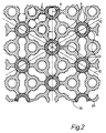
- FIGS. 1 and 2 The embodiment according to FIGS. 1 and 2 is preferably used with pipes arranged relatively close to one another, where the pipe spacing is approximately half the pipe diameter or even less.
- Fig. 1 shows a section 2 of a disc 2 of such a support grate in plan view, a few tubes 4 also being indicated.
- the tubes 4 and, accordingly, corresponding through-holes 6 of the disk 2 are arranged in the 60 ° pitch pattern which is customary for tube bundles, as is symbolized by lines 8, 10 and 12, which indicate the position of the main axes of the tube pitch pattern.
- extension 14 in question extends so far that it extends to the vicinity of the next but one surrounding bores, 6c, i.e. around them there is still a closed wall 16 of a thickness which is approximately equal to that of the web 18 between successive bores 6.
- All of the disks 2 of the support grates in question can be produced congruently one on top of the other in a single drilling process.
- two such disks 2 are then placed side-by-side at a certain distance, for example in the order of magnitude of a bore diameter, and are connected to one another in some way, the pattern of FIG. 2 resulting in a plan view.
- all pipes, regardless of the extensions 14, are enclosed in one of the two disks 2, at least over the major part of their circumference, by the supporting grate, as a result of which the pipes are held in place.
- the support grate in the area of each tube, has a relatively large passage cross-section in order to enable the heat transfer medium to pass through the tube axis with little restriction.
- FIGS. 3 and 4 are particularly suitable for tube bundles with tubes that are relatively far apart, since, as can be seen in FIG. 4, it has a particularly large tube cross-section. Ie this would be the passage cross-section also still present when the two disks 22a and 22b concerned lie directly on top of one another.
- each of the disks 22a and 22b - henceforth referred to uniformly as 22 - is obtained by the fact that every second line in every second line with a 60 ° pipe division pattern in the direction of the main pipe division axes (lines 24, 26 and 28) of the relevant bores 30, designated 30a for distinction, is expanded concentrically in the vicinity of the bores 30b around it.
- the extensions in question are designated by 32. Since the intermediate webs 34 also leave room for this, further through-bores 36 are provided in the middle between three through-bores 30 and widenings 32 in order to enlarge the passage cross-section.
- Two - or even more - of the disks 22 can now in turn be connected side-by-side at a distance one above the other, similar to the case with the disks 2 in the exemplary embodiment described first, in order to form the finished support grate according to FIG. 4.
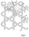
- the respective disks 2 and 22 can also be produced in a coherent manner by means of simple drilling or milling processes in order to continue to form an integral part from now on.
- FIG. 5 Such an example is shown in FIG. 5.
- the support grid in question can be obtained by first introducing through-holes 6 for all tubes in a one-piece plate 38 and then alternately enlarging the respective extensions 14 from both sides, in each case via the Middle plane 40 of the plate 38 also be produced.
- the two disks 2a and 2b thus obtained are still connected to one another via material areas 42 which surround the closed through-holes 6d which are common to the two disks, that is to say which have remained in full wall.
- FIGS. 6 and 7 also show, namely FIG. 6 for the embodiment according to FIGS. 1 and 2 and FIG. 7 for the embodiment according to FIGS. 3 and 4, a possibility of further increasing the passage cross section of the support grate in that the closed holes 6 and 30 of each disc are provided with tab-shaped extensions 6d and 30c, as are obtained, for example, by a ring of previously made smaller holes, while the remaining hole wall sections 6e and 30d take over the support of the tubes.
Landscapes
- Engineering & Computer Science (AREA)
- Chemical & Material Sciences (AREA)
- Physics & Mathematics (AREA)
- Thermal Sciences (AREA)
- Mechanical Engineering (AREA)
- General Engineering & Computer Science (AREA)
- Organic Chemistry (AREA)
- Chemical Kinetics & Catalysis (AREA)
- Heat-Exchange Devices With Radiators And Conduit Assemblies (AREA)
- Supports For Pipes And Cables (AREA)
Claims (6)
- Grille de support pour faisceaux de tubes pour supporter les tubes (4) les uns par rapport aux autres et en commun en vue d'éviter un fléchissement latéral par rapport à l'axe des tubes, cette grille présentant des ouvertures individuelles pour le passage des différents tubes, et comportant au moins deux disques (2; 22) reliés entre eux et disposés perpendiculairement à l'axe des tubes, les ouvertures de passage étant formées dans les disques par des alésages traversants (6; 30), de tel alésages de disques successifs, qui correspondent entre eux, étant décalés entre eux et pouvant venir en contact avec les tubes seulement sur des régions limitées de la périphérie du tube,
caractérisée en ce que les disques (2; 22) sont espacés d'un certain intervalle, que les alésages traversants (6; 30) ont un diamètre correspondant an diamètre extérieur du tube et sont répartis selon un motif de partage régulier des tubes de 60°, mais que, vu dans la direction de l'un des axes principaux de partage des tubes (lignes 8, 10, 12 ; 24, 26, 28), dans chaque nième rangée, chaque nième alésage traversant est élargi concentriquement jusqu'au voisinage des alésages (n-1) (6; 30) situés autour, n étant égal à 2 ou 3, et les élargissements (14, 30) de disques successifs (2a, 2b; 22a, 22b) étant décalés entre eux de manière à ce qu'un tel élargissement de l'un des disques soit agencé coaxialement à un alésage restant fermé (6c; 30b) de l'autre disque. - Grille de support selon la revendication 1,
caractérisée en ce que le nombre de disques (2; 22) reliés entre eux est de deux. - Grille de support selon la revendication 1 ou 2,
caractérisée en ce que les disques (2; 22) reliés entre eux sont solidarisés entre eux par eu moins un certain nombre d'étendues de matière (42) entourent des alésages traversants alignés et restant fermés (6c;, 30b) des disques, et comblant la distance entre lesdits disques. - Grille de support selon la revendication 3,
caractérisée en ce que les étendues de matière (42) ont le profil des régions de disque (20) qui se chevauchent et entourent les alésages alignés correspondants (6a; 30b). - Grille de support selon l'une des revendications précédentes,
caractérisée en ce qu'au moins les alésages restent fermés (6c; 30b) sont munis d'élargissements (6d, 30c) en forme de pattes. - Grille de support selon l'une des revendications précédentes,
caractérisée en ce que les nervures (34) présentent entre les alésages restent fermés (30b) de chaque disque (22), dans le mesure où le solidité n'en est pas affectée, des alésages traversants supplémentaires (36) dans le direction des axes d'alésage.
Priority Applications (3)
| Application Number | Priority Date | Filing Date | Title |
|---|---|---|---|
| EP92107549A EP0568713B1 (fr) | 1992-05-05 | 1992-05-05 | Grille de support pour faisceau de tubes |
| DE59205864T DE59205864D1 (de) | 1992-05-05 | 1992-05-05 | Stützrost für Rohrbündel |
| US08/054,817 US5366188A (en) | 1992-05-05 | 1993-04-28 | Support for sheaves of pipe |
Applications Claiming Priority (1)
| Application Number | Priority Date | Filing Date | Title |
|---|---|---|---|
| EP92107549A EP0568713B1 (fr) | 1992-05-05 | 1992-05-05 | Grille de support pour faisceau de tubes |
Publications (2)
| Publication Number | Publication Date |
|---|---|
| EP0568713A1 EP0568713A1 (fr) | 1993-11-10 |
| EP0568713B1 true EP0568713B1 (fr) | 1996-03-27 |
Family
ID=8209594
Family Applications (1)
| Application Number | Title | Priority Date | Filing Date |
|---|---|---|---|
| EP92107549A Expired - Lifetime EP0568713B1 (fr) | 1992-05-05 | 1992-05-05 | Grille de support pour faisceau de tubes |
Country Status (3)
| Country | Link |
|---|---|
| US (1) | US5366188A (fr) |
| EP (1) | EP0568713B1 (fr) |
| DE (1) | DE59205864D1 (fr) |
Families Citing this family (12)
| Publication number | Priority date | Publication date | Assignee | Title |
|---|---|---|---|---|
| CA2474935C (fr) * | 2002-02-05 | 2011-05-03 | Shell Internationale Research Maatschappij B.V. | Faisceau de tubes |
| JP4570168B2 (ja) * | 2003-08-06 | 2010-10-27 | シエル・インターナシヨネイル・リサーチ・マーチヤツピイ・ベー・ウイ | 展伸金属 |
| US8523119B1 (en) | 2003-08-26 | 2013-09-03 | Securus, Inc. | Pipe support bracket |
| AU2004304015B2 (en) * | 2003-12-22 | 2008-04-17 | Brembana & Rolle S.P.A. | Support for a tube bundle |
| JP2005221118A (ja) * | 2004-02-04 | 2005-08-18 | Japan Steel Works Ltd:The | 多管式熱交換器 |
| US20050173597A1 (en) * | 2004-02-11 | 2005-08-11 | Patterson Ventilation Co., Inc. | Pipe and cable support apparatus and method |
| CN100334415C (zh) * | 2004-09-29 | 2007-08-29 | 华南理工大学 | 旋流网板支承管束的管壳式换热器及其强化传热方法 |
| JP5072388B2 (ja) * | 2007-02-27 | 2012-11-14 | 三菱重工業株式会社 | 蒸気発生器の管支持板 |
| CN103376018B (zh) * | 2012-04-20 | 2015-09-02 | 约克(无锡)空调冷冻设备有限公司 | 一种用于管壳式换热器的管束支承件 |
| US10502451B2 (en) * | 2017-05-02 | 2019-12-10 | Rheem Manufacturing Company | Diffuser plates and diffuser plates assemblies |
| US10451365B2 (en) * | 2017-06-02 | 2019-10-22 | Rheem Manufacturing Company | Tube sheets and tube sheet assemblies |
| CN116734652A (zh) * | 2022-03-09 | 2023-09-12 | 开利公司 | 用于热交换器的非金属隔板 |
Family Cites Families (7)
| Publication number | Priority date | Publication date | Assignee | Title |
|---|---|---|---|---|
| NL102607C (fr) * | 1952-03-07 | |||
| US2902821A (en) * | 1954-11-01 | 1959-09-08 | Jr Leo J Kelly | Fastener joint for spangles and other members of flexible resilient material |
| FR1573762A (fr) * | 1968-06-19 | 1969-07-04 | ||
| US4204305A (en) * | 1971-08-27 | 1980-05-27 | The Babcock & Wilcox Company | Method of assembling a heat exchange apparatus |
| CH613138A5 (fr) * | 1976-09-06 | 1979-09-14 | Sulzer Ag | |
| US4570703A (en) * | 1982-02-08 | 1986-02-18 | The United States Of America As Represented By The United States Department Of Energy | Tube support grid and spacer therefor |
| DE4008239C1 (fr) * | 1990-03-15 | 1991-12-19 | Deutsche Airbus Gmbh, 2103 Hamburg, De |
-
1992
- 1992-05-05 EP EP92107549A patent/EP0568713B1/fr not_active Expired - Lifetime
- 1992-05-05 DE DE59205864T patent/DE59205864D1/de not_active Expired - Lifetime
-
1993
- 1993-04-28 US US08/054,817 patent/US5366188A/en not_active Expired - Lifetime
Also Published As
| Publication number | Publication date |
|---|---|
| EP0568713A1 (fr) | 1993-11-10 |
| US5366188A (en) | 1994-11-22 |
| DE59205864D1 (de) | 1996-05-02 |
Similar Documents
| Publication | Publication Date | Title |
|---|---|---|
| EP0545956B1 (fr) | Ressorts en poches pour matelas | |
| EP0568713B1 (fr) | Grille de support pour faisceau de tubes | |
| EP0609664B1 (fr) | Toile de séchage et son procédé de fabrication | |
| DE69012606T2 (de) | Kernbrennstab-Abstandshalter. | |
| DE19528117B4 (de) | Wärmeübertrager mit Plattenstapelaufbau | |
| AT1085U1 (de) | Spinndüse | |
| EP0655275A1 (fr) | Dispositif de mélange statique | |
| DE2642521C2 (de) | Vorrichtung zum gegenseitigen Distanzieren paralleler zylindrischer Elemente, die der Wärmeübertragung dienen | |
| DE2916065C2 (de) | Datenverarbeitungseinrichtung | |
| DE7616515U1 (de) | Nadelbett fuer eine strickmaschine | |
| CH662900A5 (de) | Flexibler steuerstab fuer einen kernreaktor. | |
| EP0159685B1 (fr) | Procédé de fabrication des plaques d'un échangeur de chaleur et échangeur de chaleur réalisé à partir desdites plaques | |
| DE3832910C2 (fr) | ||
| DE2263056C3 (de) | Distanzierungsgitter für Rohrbündelwärmetauscher | |
| EP0158323A1 (fr) | Yarn package carrier | |
| EP1620861B1 (fr) | Element combustible destine a un reacteur nucleaire hydraulique | |
| DE1484116C3 (de) | Bewehrungsmattenreihe | |
| WO1993024933A1 (fr) | Faisceau d'elements combustibles de reacteur nucleaire avec ecarteur hexagonal constitue d'un assemblage d'elements de base | |
| DE69008200T2 (de) | Zwischenmischgitter. | |
| DE3008455C2 (fr) | ||
| DE4332678A1 (de) | Brennelement für einen Leichtwasser-Kernreaktor | |
| DE2840146A1 (de) | Vorrichtung zur halterung eines rohrbuendels | |
| DE69102589T2 (de) | Kernbrennstabbündelabstandhalter mit Dreiecksmuster und Anwendung in Kernbrennstabbündel. | |
| DE3530236A1 (de) | Beabstandungs- und haltegitter und brennelementkassette mit einem solchen gitter | |
| DE3136866C2 (de) | Röhrenwärmetauscher mit Strömungsleiteinbauten |
Legal Events
| Date | Code | Title | Description |
|---|---|---|---|
| PUAI | Public reference made under article 153(3) epc to a published international application that has entered the european phase |
Free format text: ORIGINAL CODE: 0009012 |
|
| AK | Designated contracting states |
Kind code of ref document: A1 Designated state(s): BE DE FR GB IT NL |
|
| 17P | Request for examination filed |
Effective date: 19940509 |
|
| 17Q | First examination report despatched |
Effective date: 19950707 |
|
| GRAH | Despatch of communication of intention to grant a patent |
Free format text: ORIGINAL CODE: EPIDOS IGRA |
|
| ITF | It: translation for a ep patent filed | ||
| GRAA | (expected) grant |
Free format text: ORIGINAL CODE: 0009210 |
|
| AK | Designated contracting states |
Kind code of ref document: B1 Designated state(s): BE DE FR GB IT NL |
|
| GBT | Gb: translation of ep patent filed (gb section 77(6)(a)/1977) |
Effective date: 19960328 |
|
| REF | Corresponds to: |
Ref document number: 59205864 Country of ref document: DE Date of ref document: 19960502 |
|
| ET | Fr: translation filed | ||
| PLBE | No opposition filed within time limit |
Free format text: ORIGINAL CODE: 0009261 |
|
| STAA | Information on the status of an ep patent application or granted ep patent |
Free format text: STATUS: NO OPPOSITION FILED WITHIN TIME LIMIT |
|
| 26N | No opposition filed | ||
| REG | Reference to a national code |
Ref country code: GB Ref legal event code: IF02 |
|
| NLT1 | Nl: modifications of names registered in virtue of documents presented to the patent office pursuant to art. 16 a, paragraph 1 |
Owner name: MAN DWE GMBH |
|
| REG | Reference to a national code |
Ref country code: FR Ref legal event code: CD |
|
| PGFP | Annual fee paid to national office [announced via postgrant information from national office to epo] |
Ref country code: NL Payment date: 20080515 Year of fee payment: 17 |
|
| PGFP | Annual fee paid to national office [announced via postgrant information from national office to epo] |
Ref country code: GB Payment date: 20080522 Year of fee payment: 17 |
|
| GBPC | Gb: european patent ceased through non-payment of renewal fee |
Effective date: 20090505 |
|
| NLV4 | Nl: lapsed or anulled due to non-payment of the annual fee |
Effective date: 20091201 |
|
| PG25 | Lapsed in a contracting state [announced via postgrant information from national office to epo] |
Ref country code: NL Free format text: LAPSE BECAUSE OF NON-PAYMENT OF DUE FEES Effective date: 20091201 |
|
| PG25 | Lapsed in a contracting state [announced via postgrant information from national office to epo] |
Ref country code: GB Free format text: LAPSE BECAUSE OF NON-PAYMENT OF DUE FEES Effective date: 20090505 |
|
| PGFP | Annual fee paid to national office [announced via postgrant information from national office to epo] |
Ref country code: FR Payment date: 20100611 Year of fee payment: 19 |
|
| PGFP | Annual fee paid to national office [announced via postgrant information from national office to epo] |
Ref country code: IT Payment date: 20100520 Year of fee payment: 19 Ref country code: DE Payment date: 20100521 Year of fee payment: 19 |
|
| PGFP | Annual fee paid to national office [announced via postgrant information from national office to epo] |
Ref country code: BE Payment date: 20100517 Year of fee payment: 19 |
|
| BERE | Be: lapsed |
Owner name: *MAN DWE G.M.B.H. Effective date: 20110531 |
|
| REG | Reference to a national code |
Ref country code: FR Ref legal event code: ST Effective date: 20120131 |
|
| PG25 | Lapsed in a contracting state [announced via postgrant information from national office to epo] |
Ref country code: IT Free format text: LAPSE BECAUSE OF NON-PAYMENT OF DUE FEES Effective date: 20110505 |
|
| REG | Reference to a national code |
Ref country code: DE Ref legal event code: R119 Ref document number: 59205864 Country of ref document: DE Effective date: 20111201 |
|
| PG25 | Lapsed in a contracting state [announced via postgrant information from national office to epo] |
Ref country code: BE Free format text: LAPSE BECAUSE OF NON-PAYMENT OF DUE FEES Effective date: 20110531 |
|
| PG25 | Lapsed in a contracting state [announced via postgrant information from national office to epo] |
Ref country code: FR Free format text: LAPSE BECAUSE OF NON-PAYMENT OF DUE FEES Effective date: 20110531 |
|
| PG25 | Lapsed in a contracting state [announced via postgrant information from national office to epo] |
Ref country code: DE Free format text: LAPSE BECAUSE OF NON-PAYMENT OF DUE FEES Effective date: 20111201 |