EP0568730A1 - Dispositif de contrôle de position - Google Patents
Dispositif de contrôle de position Download PDFInfo
- Publication number
- EP0568730A1 EP0568730A1 EP92118919A EP92118919A EP0568730A1 EP 0568730 A1 EP0568730 A1 EP 0568730A1 EP 92118919 A EP92118919 A EP 92118919A EP 92118919 A EP92118919 A EP 92118919A EP 0568730 A1 EP0568730 A1 EP 0568730A1
- Authority
- EP
- European Patent Office
- Prior art keywords
- workpiece
- monitoring device
- flow channel
- position monitoring
- contact surface
- Prior art date
- Legal status (The legal status is an assumption and is not a legal conclusion. Google has not performed a legal analysis and makes no representation as to the accuracy of the status listed.)
- Granted
Links
Images


Classifications
-
- B—PERFORMING OPERATIONS; TRANSPORTING
- B23—MACHINE TOOLS; METAL-WORKING NOT OTHERWISE PROVIDED FOR
- B23Q—DETAILS, COMPONENTS, OR ACCESSORIES FOR MACHINE TOOLS, e.g. ARRANGEMENTS FOR COPYING OR CONTROLLING; MACHINE TOOLS IN GENERAL CHARACTERISED BY THE CONSTRUCTION OF PARTICULAR DETAILS OR COMPONENTS; COMBINATIONS OR ASSOCIATIONS OF METAL-WORKING MACHINES, NOT DIRECTED TO A PARTICULAR RESULT
- B23Q17/00—Arrangements for observing, indicating or measuring on machine tools
- B23Q17/006—Arrangements for observing, indicating or measuring on machine tools for indicating the presence of a work or tool in its holder
Definitions
- the invention relates to a position monitoring device on a workpiece holder, which is used to hold and clamp workpieces to be supplied in particular to a numerically controlled workpiece processing machine, with positioning elements which are connected to a base plate or the like.
- the workpiece holder and are provided with contact surfaces for the workpiece.
- Workpiece processing machines are increasingly constructed so that the tools for machining the workpieces are fed in a horizontal direction.
- This means that the workpieces to be machined must be aligned and attached to a vertically arranged base plate.
- the workpieces must therefore Connection to the base plate pressed against the positioning elements and held in this position during clamping.
- Thin metal foils are used for this purpose, with which a gap that may exist between the workpiece and the positioning element can be detected.
- this check is a tedious and time-consuming process if the positioning element is difficult to access.
- the invention has for its object to provide a position monitoring device on a workpiece holder, which enables a reliable check and monitoring of the system of the workpieces on the positioning elements with a simple structure and reliable operation.
- the positioning elements are provided with a flow channel for a gaseous medium
- the mouth facing the workpiece can be closed by the workpiece directly or by a pressure piece adjacent to the workpiece and the other end via a hose line with a pressure feed device is connected, which is provided for each connected positioning element with a throttle device and a pressure sensor downstream of the throttle device in the flow direction of the medium, the pressure sensor providing a signal device when the pressure falls below a predetermined value operated.
- the advantage achieved by the invention consists essentially in that when clamping the workpieces to be machined, only the signaling devices provided for each positioning element must be observed in order to ensure that the workpiece is connected and clamped to the base plate or the like in the prescribed position is.
- a corresponding logical connection of the individual signaling devices also gives the option of only giving a signal if there is insufficient contact of the workpiece on at least one of the positioning elements.
- the signal device can also be used to control the workpiece processing machine, for example, a shutdown of the machine can be initiated if, for. B. during machining of a workpiece, this detaches itself from the intended position, ie is no longer in contact with at least one of the positioning elements. In this way, damage to both the workpiece and the workpiece processing machine can be avoided.
- the flow channel has a section with a reduced cross section at its mouth end. In this way, an essentially constant pressure is maintained in the flow channel until immediately before the contact surface.
- the invention provides in an expedient embodiment that the cross-sectional area of the flow channel at the mouth is smaller by a factor of 100 compared to the contact surface.
- the flow conditions are set so that an evaluable pressure difference occurs in the distance range to be monitored between the contact surface and the workpiece.
- the flow channel in the positioning element runs at right angles, the end facing away from the mouth being provided with a connecting nipple for the hose line.
- the positioning elements can be fastened to the base plate in a conventional manner without having to accept restrictions with regard to the arrangement because of the hoses to be connected. Rather, they run in a plane parallel to the base area.
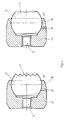
- the positioning element consists of a base element and a workpiece support bolt, which forms the contact surface for the workpiece, the workpiece support bolt being provided with a cylindrical pin and an adjoining annular collar, the end face of which forms the contact surface, and wherein the pin is inserted tightly into a receiving bore of the base element, into which a supply bore forming part of the flow channel opens.
- the positioning element is designed as a pendulum support, in which a flattened ball forming the contact surface is arranged in a bearing body partially encompassing the ball, the ball being in the direction perpendicular to the contact surface with little play is movable and in its position adjusted towards the workpiece opens an annular gap between its surface and the inner surface of the bearing body for the passage of the gaseous medium.
- This design has the particular advantage that the contact surface coming into contact with the workpiece does not have to be flat, as is necessary when the flow channel opens directly into the contact surface.
- the contact surface can be designed here as a corrugated surface.
- the system can be monitored on the positioning element of workpieces that have a - still - rough surface.
- the bearing body can expediently be provided with at least one outlet opening which is arranged in the flow direction of the medium behind the annular gap in the collar encompassing the ball. This ensures that the gaseous medium escapes even when the collar seals the ball.
- the position monitoring device which is used to control the placement of the workpieces on positioning elements 1 of a workpiece holder, is shown only schematically in the drawing together with some embodiments of the positioning elements 1 used.
- the workpiece holder (not shown) is intended for holding and clamping workpieces, which are to be fed in particular to a numerically controlled workpiece processing machine.
- the positioning elements 1 are connected to a base plate or the like, for which purpose this can be provided with T-slots arranged at right angles to one another and provided with a contact surface 1.1 for the workpiece.
- the positioning elements 1 are provided in detail with a flow channel 2 for a gaseous medium, the mouth 3 of which faces the workpiece can be closed either directly by the workpiece or by a pressure piece which bears against the workpiece.
- the other end of the flow channel 2 is connected via a hose 4 to a pressure feed device 5, which has a throttle device (not shown in detail) for each connected positioning element 1.
- the throttle device is in the flow direction of the medium a pressure sensor, also not shown, is connected downstream, by means of which a signal device is actuated when the pressure falls below a predetermined value. 1, the throttle device and the pressure sensor are part of the pressure feed device 5.
- the pressure feed device 5 is also preceded by a filter control valve 14, which is also only shown schematically.
- the mouth 3 of the flow channel 2 is almost completely closed, so that a correspondingly high pressure builds up in the flow channel 2 and is registered by the pressure sensor. If, on the other hand, the workpiece of the contact surface 11 is not or not completely in contact, the gaseous medium escapes through the mouth 3 of the flow channel 2, so that a considerably lower pressure prevails in the flow channel 2 due to the throttle device. This lower pressure is sensed by the pressure sensor, which then actuates the signaling device below a certain switching threshold. In this way, the prescribed placement of the workpiece on the contact surface 1.1 can be checked by simply observing the signaling device.
- the flow channel 2 has a section with a reduced cross section at its mouth end.
- the cross-sectional area of the flow channel 2 at the mouth 3 is usually selected so that it is about a factor 100 smaller than the contact surface 1.1.
- the flow channel 2 is preferably at right angles in the positioning element 1, the end facing away from the mouth 3 being provided with a connecting nipple 6 for the hose line 4.
- the positioning elements 1 can be connected to the base plate in a conventional manner, since the hose lines 4 run in a plane parallel to the surface of the base plate and can be laid as desired between the positioning elements 1.
- the positioning element 1 consists of a base element 7 and a workpiece support bolt 8, which forms the support surface 1.1 for the workpiece.
- the workpiece support pin 8 is provided with a cylindrical pin 9 and an adjoining collar 10, the end face of which forms the contact surface 1.1.
- the pin 9 is inserted tightly into a receiving bore of the base element 7, into which a supply bore 11, which forms part of the flow channel 2, opens. This makes it possible to easily replace the workpiece support bolt 8 with another without loosening the hose lines 4.
- the positioning element as a pendulum support, as shown in FIG. 4.
- a flattened ball 12 forming the contact surface 1.1 is arranged in a bearing body 13 which partially encompasses the ball.
- the ball 12 is movable in a manner not shown in the drawing in a direction substantially perpendicular to the contact surface with little play.
- the ball 12 opens an annular gap between its surface and the inner surface of the bearing body 13, through which the gaseous medium can pass.
- the ball 12 forms the pressure piece closing the mouth 3.
Landscapes
- Engineering & Computer Science (AREA)
- Mechanical Engineering (AREA)
- Machine Tool Sensing Apparatuses (AREA)
- Measuring Arrangements Characterized By The Use Of Fluids (AREA)
- Jigs For Machine Tools (AREA)
Applications Claiming Priority (2)
| Application Number | Priority Date | Filing Date | Title |
|---|---|---|---|
| DE4214320A DE4214320C1 (fr) | 1992-05-04 | 1992-05-04 | |
| DE4214320 | 1992-05-04 |
Publications (2)
| Publication Number | Publication Date |
|---|---|
| EP0568730A1 true EP0568730A1 (fr) | 1993-11-10 |
| EP0568730B1 EP0568730B1 (fr) | 1997-10-22 |
Family
ID=6457882
Family Applications (1)
| Application Number | Title | Priority Date | Filing Date |
|---|---|---|---|
| EP92118919A Expired - Lifetime EP0568730B1 (fr) | 1992-05-04 | 1992-11-05 | Dispositif de contrÔle de position |
Country Status (4)
| Country | Link |
|---|---|
| US (1) | US5279493A (fr) |
| EP (1) | EP0568730B1 (fr) |
| JP (1) | JPH0615545A (fr) |
| DE (1) | DE4214320C1 (fr) |
Cited By (3)
| Publication number | Priority date | Publication date | Assignee | Title |
|---|---|---|---|---|
| DE19608879A1 (de) * | 1996-03-07 | 1997-09-11 | Bayerische Motoren Werke Ag | Vorrichtung für eine pneumatische Auflagekontrolle insbesondere eines Werkstückes |
| DE19734374A1 (de) * | 1997-08-08 | 1999-02-18 | Audi Ag | Einrichtung zur pneumatischen Lagebestimmung von Werkstücken |
| US8152710B2 (en) | 2006-04-06 | 2012-04-10 | Ethicon Endo-Surgery, Inc. | Physiological parameter analysis for an implantable restriction device and a data logger |
Families Citing this family (25)
| Publication number | Priority date | Publication date | Assignee | Title |
|---|---|---|---|---|
| US5427363A (en) * | 1993-06-14 | 1995-06-27 | Cna Manufacturing Systems, Inc. | End effector |
| US5383948A (en) * | 1993-07-06 | 1995-01-24 | Corning Incorporated | Method and apparatus for crackoff and neck sealing of cathode ray tube funnels |
| US5657972A (en) * | 1994-12-22 | 1997-08-19 | Isi Norgren, Inc. | Clamp with inflatable bladder |
| US5810340A (en) * | 1996-09-06 | 1998-09-22 | Lucent Technologies Inc. | Precision clamping device with digitally programmable load |
| ITBO20040420A1 (it) | 2004-07-07 | 2004-10-07 | Type S R L | Macchina per taglio e formatura di piattine metalliche |
| US7775966B2 (en) | 2005-02-24 | 2010-08-17 | Ethicon Endo-Surgery, Inc. | Non-invasive pressure measurement in a fluid adjustable restrictive device |
| US7658196B2 (en) | 2005-02-24 | 2010-02-09 | Ethicon Endo-Surgery, Inc. | System and method for determining implanted device orientation |
| US8016744B2 (en) | 2005-02-24 | 2011-09-13 | Ethicon Endo-Surgery, Inc. | External pressure-based gastric band adjustment system and method |
| US7927270B2 (en) | 2005-02-24 | 2011-04-19 | Ethicon Endo-Surgery, Inc. | External mechanical pressure sensor for gastric band pressure measurements |
| US8066629B2 (en) | 2005-02-24 | 2011-11-29 | Ethicon Endo-Surgery, Inc. | Apparatus for adjustment and sensing of gastric band pressure |
| US7775215B2 (en) | 2005-02-24 | 2010-08-17 | Ethicon Endo-Surgery, Inc. | System and method for determining implanted device positioning and obtaining pressure data |
| US7699770B2 (en) | 2005-02-24 | 2010-04-20 | Ethicon Endo-Surgery, Inc. | Device for non-invasive measurement of fluid pressure in an adjustable restriction device |
| ITBO20050481A1 (it) * | 2005-07-19 | 2007-01-20 | Silicon Biosystems S R L | Metodo ed apparato per la manipolazione e/o l'individuazione di particelle |
| ITBO20050646A1 (it) * | 2005-10-26 | 2007-04-27 | Silicon Biosystem S R L | Metodo ed apparato per la caratterizzazione ed il conteggio di particelle |
| ITTO20060226A1 (it) | 2006-03-27 | 2007-09-28 | Silicon Biosystem S P A | Metodo ed apparato per il processamento e o l'analisi e o la selezione di particelle, in particolare particelle biologiche |
| US8870742B2 (en) | 2006-04-06 | 2014-10-28 | Ethicon Endo-Surgery, Inc. | GUI for an implantable restriction device and a data logger |
| ITTO20070771A1 (it) | 2007-10-29 | 2009-04-30 | Silicon Biosystems Spa | Metodo e apparato per la identificazione e manipolazione di particelle |
| IT1391619B1 (it) | 2008-11-04 | 2012-01-11 | Silicon Biosystems Spa | Metodo per l'individuazione, selezione e analisi di cellule tumorali |
| US10895575B2 (en) | 2008-11-04 | 2021-01-19 | Menarini Silicon Biosystems S.P.A. | Method for identification, selection and analysis of tumour cells |
| JP5834001B2 (ja) | 2009-03-17 | 2015-12-16 | シリコン・バイオシステムズ・ソシエタ・ペル・アチオニ | 細胞を分離するためのマイクロ流体デバイス |
| IT1403518B1 (it) | 2010-12-22 | 2013-10-31 | Silicon Biosystems Spa | Dispositivo microfluidico per la manipolazione di particelle |
| ES2413910B1 (es) * | 2011-07-29 | 2014-08-04 | Universidad Carlos Iii De Madrid | Sistema neumático de detección de presencia y posicionado de pieza para procesos automáticos |
| ITTO20110990A1 (it) | 2011-10-28 | 2013-04-29 | Silicon Biosystems Spa | Metodo ed apparato per l'analisi ottica di particelle a basse temperature |
| ITBO20110766A1 (it) | 2011-12-28 | 2013-06-29 | Silicon Biosystems Spa | Dispositivi, apparato, kit e metodo per il trattamento di un campione biologico |
| US11022953B2 (en) | 2019-05-07 | 2021-06-01 | Cna Manufacturing Systems, Inc. | Flexible tooling system |
Citations (3)
| Publication number | Priority date | Publication date | Assignee | Title |
|---|---|---|---|---|
| US3353402A (en) * | 1965-05-24 | 1967-11-21 | Tripoli Joseph V | Fluid centering and sensing devices |
| US3603203A (en) * | 1970-01-12 | 1971-09-07 | Pratt & Whitney Inc | Pneumatic tool-sensing system for machine tool |
| EP0151709A2 (fr) * | 1984-01-28 | 1985-08-21 | SMW Schneider & Weisshaupt GmbH | Dispositif de surveillance de l'état d'un mandrin |
Family Cites Families (7)
| Publication number | Priority date | Publication date | Assignee | Title |
|---|---|---|---|---|
| GB1240102A (en) * | 1967-07-12 | 1971-07-21 | Jones William O M | Improvements in and relating to machine tools |
| JPS5813946U (ja) * | 1981-07-21 | 1983-01-28 | 相生精機株式会社 | 工作機械へのワ−ク等の交換装置 |
| JPS60172B2 (ja) * | 1981-12-21 | 1985-01-07 | 東芝機械株式会社 | 立旋盤の主軸構造 |
| US4909521A (en) * | 1982-04-26 | 1990-03-20 | The S-P Manufacturing Corporation | Chuck having gripping and locating sensors |
| DE3341542A1 (de) * | 1983-11-17 | 1985-05-30 | Günter 3548 Arolsen Meywald | Spanneinrichtung zur verwendung an oder in bearbeitungsstationen von werkzeugmaschinen |
| DE3402988A1 (de) * | 1984-01-28 | 1985-08-08 | SMW Schneider & Weißhaupt GmbH, 7996 Meckenbeuren | Einrichtung zur ueberwachung des betriebszustandes eines kraftspannfutters |
| DE3635716A1 (de) * | 1986-10-21 | 1988-04-28 | Lewecke Gmbh Maschbau | Spannvorrichtung fuer holzmaterial |
-
1992
- 1992-05-04 DE DE4214320A patent/DE4214320C1/de not_active Expired - Fee Related
- 1992-11-05 EP EP92118919A patent/EP0568730B1/fr not_active Expired - Lifetime
- 1992-12-09 US US07/988,174 patent/US5279493A/en not_active Expired - Fee Related
-
1993
- 1993-04-30 JP JP5104448A patent/JPH0615545A/ja active Pending
Patent Citations (3)
| Publication number | Priority date | Publication date | Assignee | Title |
|---|---|---|---|---|
| US3353402A (en) * | 1965-05-24 | 1967-11-21 | Tripoli Joseph V | Fluid centering and sensing devices |
| US3603203A (en) * | 1970-01-12 | 1971-09-07 | Pratt & Whitney Inc | Pneumatic tool-sensing system for machine tool |
| EP0151709A2 (fr) * | 1984-01-28 | 1985-08-21 | SMW Schneider & Weisshaupt GmbH | Dispositif de surveillance de l'état d'un mandrin |
Cited By (4)
| Publication number | Priority date | Publication date | Assignee | Title |
|---|---|---|---|---|
| DE19608879A1 (de) * | 1996-03-07 | 1997-09-11 | Bayerische Motoren Werke Ag | Vorrichtung für eine pneumatische Auflagekontrolle insbesondere eines Werkstückes |
| DE19734374A1 (de) * | 1997-08-08 | 1999-02-18 | Audi Ag | Einrichtung zur pneumatischen Lagebestimmung von Werkstücken |
| DE19734374C2 (de) * | 1997-08-08 | 2003-01-02 | Audi Ag | Einrichtung zur pneumatischen Lagebestimmung von Werkstücken |
| US8152710B2 (en) | 2006-04-06 | 2012-04-10 | Ethicon Endo-Surgery, Inc. | Physiological parameter analysis for an implantable restriction device and a data logger |
Also Published As
| Publication number | Publication date |
|---|---|
| US5279493A (en) | 1994-01-18 |
| DE4214320C1 (fr) | 1993-06-03 |
| EP0568730B1 (fr) | 1997-10-22 |
| JPH0615545A (ja) | 1994-01-25 |
Similar Documents
| Publication | Publication Date | Title |
|---|---|---|
| EP0568730B1 (fr) | Dispositif de contrÔle de position | |
| EP0368023B1 (fr) | Système d'outils | |
| DE3426892C2 (fr) | ||
| EP0298239B1 (fr) | Procédé et dispositif pour le contrôle de la position d'un porte-outil dans le support d'un dispositif changeur d'outils et pour le nettoyage des surfaces d'accouplement entre support et porte-outil | |
| DE3109543C2 (de) | Vorrichtung zur Kühlmittelzufuhr zu mit Kühlmittelkanälen versehenen, rotierenden Schneidwerkzeugen für die spanende Metallbearbeitung, insbesondere Bohrwerkzeugen | |
| EP2301696A1 (fr) | Interface entre un corps de réception et un insert, l'insert étant notamment développé comme support d'outil ou de pièce à usiner | |
| DE102014111567B4 (de) | Robotersystem | |
| DE69310579T2 (de) | Werkzeug-Ein- und Ausspannvorrichtung | |
| EP2353774A1 (fr) | Dispositif de serrage doté d'un sytème de compensation en hauteur | |
| EP3845343B1 (fr) | Pied magnétique | |
| DE69712972T2 (de) | Schmiedewerkzeug für den Einbau von Lagern | |
| EP0088212A1 (fr) | Commande numérique pour machines-outils | |
| DE112008001364B4 (de) | Verbinder für Fluiddruckvorrichtungen | |
| EP0001764B1 (fr) | Porte-outil à plaquette de coupe échangeable | |
| DE3025952A1 (de) | Halterung fuer ein roboterwerkzeug | |
| EP0967030B1 (fr) | Procédé et dispositif de réglage des rouleaux d'un dispositif de redressage | |
| CH658617A5 (de) | Zahnflankenschleifmaschine mit doppelkegelfoermiger schleifscheibe. | |
| EP0275923A2 (fr) | Dispositif de serrage de pièces | |
| DE3137878C2 (de) | Überlastsicherung für den Vorschubantrieb an einer Werkzeugmaschine | |
| DE2940874A1 (de) | Vorrichtung zum innenentgraten laengsnahtgeschweisster rohre | |
| EP0671599B1 (fr) | Procédé et appareil de mesure pneumatique pour contrôler des dimensions d'un objet | |
| DE3708363A1 (de) | Spannfutter fuer werkzeugmaschinen | |
| DE4410414A1 (de) | Bohrvorrichtung für harte, spröde Werkstoffe und entsprechendes Bohrverfahren | |
| CH663164A5 (de) | Schmiedemaschine mit einer arbeitsstation und einer foerdereinrichtung. | |
| DE69113984T2 (de) | Werkzeughalter mit kühlmittelkanal. |
Legal Events
| Date | Code | Title | Description |
|---|---|---|---|
| PUAI | Public reference made under article 153(3) epc to a published international application that has entered the european phase |
Free format text: ORIGINAL CODE: 0009012 |
|
| AK | Designated contracting states |
Kind code of ref document: A1 Designated state(s): CH FR GB IT LI |
|
| 17P | Request for examination filed |
Effective date: 19940411 |
|
| 17Q | First examination report despatched |
Effective date: 19960102 |
|
| GRAG | Despatch of communication of intention to grant |
Free format text: ORIGINAL CODE: EPIDOS AGRA |
|
| GRAH | Despatch of communication of intention to grant a patent |
Free format text: ORIGINAL CODE: EPIDOS IGRA |
|
| GRAH | Despatch of communication of intention to grant a patent |
Free format text: ORIGINAL CODE: EPIDOS IGRA |
|
| GRAA | (expected) grant |
Free format text: ORIGINAL CODE: 0009210 |
|
| AK | Designated contracting states |
Kind code of ref document: B1 Designated state(s): CH FR GB IT LI |
|
| ET | Fr: translation filed | ||
| REG | Reference to a national code |
Ref country code: CH Ref legal event code: NV Representative=s name: ISLER & PEDRAZZINI AG Ref country code: CH Ref legal event code: EP |
|
| ITF | It: translation for a ep patent filed | ||
| GBT | Gb: translation of ep patent filed (gb section 77(6)(a)/1977) |
Effective date: 19980119 |
|
| PGFP | Annual fee paid to national office [announced via postgrant information from national office to epo] |
Ref country code: FR Payment date: 19980729 Year of fee payment: 7 |
|
| PLBE | No opposition filed within time limit |
Free format text: ORIGINAL CODE: 0009261 |
|
| STAA | Information on the status of an ep patent application or granted ep patent |
Free format text: STATUS: NO OPPOSITION FILED WITHIN TIME LIMIT |
|
| PGFP | Annual fee paid to national office [announced via postgrant information from national office to epo] |
Ref country code: CH Payment date: 19981009 Year of fee payment: 7 |
|
| 26N | No opposition filed | ||
| PGFP | Annual fee paid to national office [announced via postgrant information from national office to epo] |
Ref country code: GB Payment date: 19981026 Year of fee payment: 7 |
|
| PG25 | Lapsed in a contracting state [announced via postgrant information from national office to epo] |
Ref country code: GB Free format text: LAPSE BECAUSE OF NON-PAYMENT OF DUE FEES Effective date: 19991105 |
|
| PG25 | Lapsed in a contracting state [announced via postgrant information from national office to epo] |
Ref country code: LI Free format text: LAPSE BECAUSE OF NON-PAYMENT OF DUE FEES Effective date: 19991130 Ref country code: CH Free format text: LAPSE BECAUSE OF NON-PAYMENT OF DUE FEES Effective date: 19991130 |
|
| GBPC | Gb: european patent ceased through non-payment of renewal fee |
Effective date: 19991105 |
|
| REG | Reference to a national code |
Ref country code: CH Ref legal event code: PL |
|
| PG25 | Lapsed in a contracting state [announced via postgrant information from national office to epo] |
Ref country code: FR Free format text: LAPSE BECAUSE OF NON-PAYMENT OF DUE FEES Effective date: 20000731 |
|
| REG | Reference to a national code |
Ref country code: FR Ref legal event code: ST |
|
| PG25 | Lapsed in a contracting state [announced via postgrant information from national office to epo] |
Ref country code: IT Free format text: LAPSE BECAUSE OF NON-PAYMENT OF DUE FEES;WARNING: LAPSES OF ITALIAN PATENTS WITH EFFECTIVE DATE BEFORE 2007 MAY HAVE OCCURRED AT ANY TIME BEFORE 2007. THE CORRECT EFFECTIVE DATE MAY BE DIFFERENT FROM THE ONE RECORDED. Effective date: 20051105 |