EP0568748A1 - Générateur de poussée à turbine avec récupération de chaleur - Google Patents
Générateur de poussée à turbine avec récupération de chaleur Download PDFInfo
- Publication number
- EP0568748A1 EP0568748A1 EP92401198A EP92401198A EP0568748A1 EP 0568748 A1 EP0568748 A1 EP 0568748A1 EP 92401198 A EP92401198 A EP 92401198A EP 92401198 A EP92401198 A EP 92401198A EP 0568748 A1 EP0568748 A1 EP 0568748A1
- Authority
- EP
- European Patent Office
- Prior art keywords
- turbine
- thrust
- wall
- rotating disc
- flow path
- Prior art date
- Legal status (The legal status is an assumption and is not a legal conclusion. Google has not performed a legal analysis and makes no representation as to the accuracy of the status listed.)
- Withdrawn
Links
- 239000007789 gas Substances 0.000 claims abstract description 37
- 238000002485 combustion reaction Methods 0.000 claims abstract description 29
- 230000006835 compression Effects 0.000 claims abstract description 9
- 238000007906 compression Methods 0.000 claims abstract description 9
- 238000001816 cooling Methods 0.000 abstract 1
- 238000007599 discharging Methods 0.000 abstract 1
- 238000011084 recovery Methods 0.000 abstract 1
- 238000000034 method Methods 0.000 description 3
- 230000001141 propulsive effect Effects 0.000 description 3
- 239000000446 fuel Substances 0.000 description 2
- 239000007787 solid Substances 0.000 description 2
- 230000001133 acceleration Effects 0.000 description 1
- 238000006243 chemical reaction Methods 0.000 description 1
- 230000000694 effects Effects 0.000 description 1
Images


Classifications
-
- F—MECHANICAL ENGINEERING; LIGHTING; HEATING; WEAPONS; BLASTING
- F02—COMBUSTION ENGINES; HOT-GAS OR COMBUSTION-PRODUCT ENGINE PLANTS
- F02C—GAS-TURBINE PLANTS; AIR INTAKES FOR JET-PROPULSION PLANTS; CONTROLLING FUEL SUPPLY IN AIR-BREATHING JET-PROPULSION PLANTS
- F02C3/00—Gas-turbine plants characterised by the use of combustion products as the working fluid
- F02C3/04—Gas-turbine plants characterised by the use of combustion products as the working fluid having a turbine driving a compressor
- F02C3/045—Gas-turbine plants characterised by the use of combustion products as the working fluid having a turbine driving a compressor having compressor and turbine passages in a single rotor-module
- F02C3/05—Gas-turbine plants characterised by the use of combustion products as the working fluid having a turbine driving a compressor having compressor and turbine passages in a single rotor-module the compressor and the turbine being of the radial flow type
-
- F—MECHANICAL ENGINEERING; LIGHTING; HEATING; WEAPONS; BLASTING
- F02—COMBUSTION ENGINES; HOT-GAS OR COMBUSTION-PRODUCT ENGINE PLANTS
- F02C—GAS-TURBINE PLANTS; AIR INTAKES FOR JET-PROPULSION PLANTS; CONTROLLING FUEL SUPPLY IN AIR-BREATHING JET-PROPULSION PLANTS
- F02C3/00—Gas-turbine plants characterised by the use of combustion products as the working fluid
- F02C3/04—Gas-turbine plants characterised by the use of combustion products as the working fluid having a turbine driving a compressor
- F02C3/045—Gas-turbine plants characterised by the use of combustion products as the working fluid having a turbine driving a compressor having compressor and turbine passages in a single rotor-module
-
- F—MECHANICAL ENGINEERING; LIGHTING; HEATING; WEAPONS; BLASTING
- F02—COMBUSTION ENGINES; HOT-GAS OR COMBUSTION-PRODUCT ENGINE PLANTS
- F02C—GAS-TURBINE PLANTS; AIR INTAKES FOR JET-PROPULSION PLANTS; CONTROLLING FUEL SUPPLY IN AIR-BREATHING JET-PROPULSION PLANTS
- F02C3/00—Gas-turbine plants characterised by the use of combustion products as the working fluid
- F02C3/14—Gas-turbine plants characterised by the use of combustion products as the working fluid characterised by the arrangement of the combustion chamber in the plant
- F02C3/145—Gas-turbine plants characterised by the use of combustion products as the working fluid characterised by the arrangement of the combustion chamber in the plant the combustion chamber being in the reverse flow-type
-
- F—MECHANICAL ENGINEERING; LIGHTING; HEATING; WEAPONS; BLASTING
- F02—COMBUSTION ENGINES; HOT-GAS OR COMBUSTION-PRODUCT ENGINE PLANTS
- F02C—GAS-TURBINE PLANTS; AIR INTAKES FOR JET-PROPULSION PLANTS; CONTROLLING FUEL SUPPLY IN AIR-BREATHING JET-PROPULSION PLANTS
- F02C7/00—Features, components parts, details or accessories, not provided for in, or of interest apart form groups F02C1/00 - F02C6/00; Air intakes for jet-propulsion plants
- F02C7/08—Heating air supply before combustion, e.g. by exhaust gases
Definitions
- This work is related to the development of heat-recovering-thrust-turbine having uniquely and distinctly rotational flow path compared with flow path of the conventional gas turbine engines.
- the invented thrust turbine shows lighter and simpler structure in parts as well as smaller in size, however, which is to develop higher thrust due to the generation of the gases having high pressure and velocity.
- the conventional gas turbine engine generally consists of compressor(s), combustion chamber(s) and turbine(s).
- compressor(s) huge quantities of air are compressed by a compressor. After this compressed air greatly heated and accelerated by burning with fuel, the air remaining after the burning process and the gases produced by combustion cause the turbine rotor, mounted on the same shaft as that of the compressor, to rotate.
- the exhaust gases flow straight forward to the nozzle exit without rotation.
- the heat-recovering-thrust-turbine with rotational flow path has a unique nozzle which has been designed to rotate the exhaust gases by an angle of 360 degrees and then, expell it outside air.
- the propulsive force or thrust of the thrust turbine is increased according as the pressure and the velocity of the exhaust gases are increased.
- the thrust turbine has several unique advantages;
- the centrifugal force of the exhaust gases can be completely converted to its thrust.
- the air from the entrance of the thrust turbine is compressed in a compression section, and rushes into a combustion chamber through the manifolds connecting the combustion chamber to the exit of the compression section, being perpendicularly placed to the center line of the thrust turbine. Therefore, part of heats included in the exhaust gases can be recovered by cold air passing through the manifolds having been devised in this work.
- the specific volume (the ratio of the engine volume to its thrust) and the specific weight (the ratio of the engine weight to its thrust) could be lowered more than that of the conventional gas turbine engines because the thrust turbine has equipped a simple and combined rotating disc to which rotor blades, for a compression and the generation of turbine power, are attached.
- the configuration of the thrust turbine devised in this work is more unique and simpler than that of the conventional gas turbine engine.
- the shape of a rotating disc is similar to the solid of revolution generated by rotating a plane of the semicircle of radius r, being laid on the positive or negative x-axis of the cartesian coordinates, through a complete revolution in space about a line on the y-axis of the cartesian coordinates.
- a combustion chamber in the shape of the inner wall of the aforementioned rotating disc is located inside the disc, so that the curved flow path of exhaust gases are made between the inner wall of the rotating disc and the outer wall of the combustion chamber.
- Rotor blades and stator blades of the turbine are attached at the inner wall of the rotating disc and the outer wall of the combustion chamber, respectively. And hot, expanding gases being heated by combustion chamber rush into the curved flow path. In this curved flow path, the gases rotate from the exit of the combustion chamber by an angle of 180 degrees and cause the turbine rotors to rotate in order to get the power for driving the di compressor blades.
- the presure force and the centrifugal force induced by the expanding gases act on the inner wall of the rotating disc, so that the propulsive force of the thrust turbine is developed.
- the compressor rotor blades on the outer wall of the rotating disc raise the pressure of the incoming air before passing it on to the combustion chamber.
- the rotating disc (1) has a unique shape similar to the solid of revolution generated by rotating a plane of the semicircle of radius r, being lain on the positive or negative x-axis of the cartesian coordinates, through a complete revolution in space about a line on the y-axis of the cartesian coordinates. And this rotating disc (1) is mounted on a shaft (10).
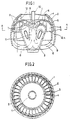
- the combustion chamber (3) whose outer shape is similar to the shape of the inner wall of the rotating disc (1) is located inside the rotating disc (1). And, it is also linked to the outer wall of the thrust turbine (2), and fixed in the middle of the inner space of the rotating disc (1) by the manifolds (6). Thus, an exhaust nozzle exit (9) and the heat recovering panels are arranged in a radial shape about the combustion chamber as shown in Fig.5.
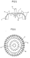
- rotor blades(8) and stator blades(7) of the turbine are attached to the inner wall of the rotating disc(1) and the outer wall of the combustion chamber(3), respectively, as shown in Fig. 1, 2, 5 and 6.
- rotor blades(4) and stator blades(5) of the compressor are attached to the outer wall of the rotating disc(1) and the inner wall of the thrust turbine case(2), respectively, so as to compress the air from the inlet(12) and cool the rotating disc(1) in the curved flow path(12A) of incoming air which is formed between the outer wall of the rotating disc(1) and the inner wall of the thrust turbine case(2) as indicated in Fig. 1 and 2.
- the rotating disc(1) including the rotor blades(4, 8) of a compressor and a turbine, rotates with constant speed
- the compressed air from the low-pressure compressor of a conventional basic turbojet engine, comes through the curved flow path of the thrust turbine.
- the compressed air cools the surface of the rotating disc(1) and the compressor rotor blades(4) being heated by combustion, and also recovers wasted heats on the hot surface of them. Then, this heated air under pressure is repressurized by the blades of rotor and stator of the compressor.
- the repressurized air enters into the combustion chamber(3) through the manifolds(13) including the heat recovering panels(6) and intersecting the exhaust nozzle exit(9). Part of the air entering into the combustion chamber(3) is used for burning the supplied fuel by the instantaneous combustion process in the combustion chamber(3). And, the remainder of the air retaining high-pressure and high-velocity is mixed with flame generated by combustion. By this process, complete combustion may be performed.
- the gases being produced by aforementioned process are expanded, accelerated and expelled to the outside air through the exhaust nozzle exit(9) via the gas discharge passage(11) at the same time as the gases rotate along the curved flow path(12A).
- the shaft power being developed by high-speed revolution of the turbine rotor blades(8) about the shaft results from the force proportioning to the pressure and the velocity of the exhaust gases.
- the propulsive force(thrust) is generated from powerful pressurized zone which is created at the inner wall of the rotating disc(1) by the centrifugal force acting to the inner wall of the rotating disc(1) and the pressure energy of exhaust gases.
- the specific volume (the ratio of the engine volume to its thrust) and the specific weight (the ratio of the engine weight to its thrust) of the thrust turbine could be superior to those of the conventional gas turbine engines.
- the centrifugal force or the velocity energy is able to be used in the thrust turbine, while it Is impossible to use the centrifugal force in the axial flow type divergent nozzle of the conventional gas turbine engine.
- the thermal efficiency of the thrust turbine may be improved since it has the capability of heat recovering.
- Advantages of the thrust turbine such as simple structure and reduced specific volume or reduced specific weight can contribute to mitigate the design restrictions of gas turbine engines in practical use.
- the compression and the turbine thrust can be concurrently produced inside and outside of the rotating disc.
Landscapes
- Engineering & Computer Science (AREA)
- Chemical & Material Sciences (AREA)
- Combustion & Propulsion (AREA)
- Mechanical Engineering (AREA)
- General Engineering & Computer Science (AREA)
- Turbine Rotor Nozzle Sealing (AREA)
- Supercharger (AREA)
Applications Claiming Priority (2)
| Application Number | Priority Date | Filing Date | Title |
|---|---|---|---|
| US07/872,915 US5241815A (en) | 1992-04-22 | 1992-04-22 | Heat-recovering-thrust-turbine having rotational flow path |
| CA002067064A CA2067064A1 (fr) | 1992-04-22 | 1992-04-24 | Turbine de poussee a recuperation de chaleur et a ecoulement tourbillonnaire |
Publications (1)
| Publication Number | Publication Date |
|---|---|
| EP0568748A1 true EP0568748A1 (fr) | 1993-11-10 |
Family
ID=25675100
Family Applications (1)
| Application Number | Title | Priority Date | Filing Date |
|---|---|---|---|
| EP92401198A Withdrawn EP0568748A1 (fr) | 1992-04-22 | 1992-04-27 | Générateur de poussée à turbine avec récupération de chaleur |
Country Status (3)
| Country | Link |
|---|---|
| US (1) | US5241815A (fr) |
| EP (1) | EP0568748A1 (fr) |
| CA (1) | CA2067064A1 (fr) |
Cited By (6)
| Publication number | Priority date | Publication date | Assignee | Title |
|---|---|---|---|---|
| WO1997002407A1 (fr) * | 1996-04-29 | 1997-01-23 | Abundancia Navarro, Juan Carlos | Turbine a gaz centrifuge |
| WO1999061767A1 (fr) * | 1998-05-29 | 1999-12-02 | Pratt & Whitney Canada Corp | Recuperateur pour moteur a turbine a gaz |
| WO2000000295A1 (fr) * | 1998-06-30 | 2000-01-06 | E.I. Du Pont De Nemours And Company | Systeme de circulation d'air pour formeur de nappe |
| RU2147691C1 (ru) * | 1998-05-26 | 2000-04-20 | Дальневосточный государственный технический университет | Турбокомпрессор |
| US7219490B2 (en) | 2000-09-05 | 2007-05-22 | D-Star Engineering | Nested core gas turbine engine |
| EP2744993A4 (fr) * | 2011-09-23 | 2015-05-20 | Socpra Sciences Et Génie S E C | Ensemble rotor avec disposition concentrique d'une partie de turbine, d'un passage de refroidissement et d'une paroi de renfort |
Families Citing this family (8)
| Publication number | Priority date | Publication date | Assignee | Title |
|---|---|---|---|---|
| RU2205972C2 (ru) * | 2001-03-29 | 2003-06-10 | Шаньгин Евгений Сергеевич | Силовая установка летательного аппарата |
| US6397577B1 (en) * | 2001-04-02 | 2002-06-04 | The United States Of America As Represented By The Secretary Of The Air Force | Shaftless gas turbine engine spool |
| US20080022693A1 (en) * | 2005-09-30 | 2008-01-31 | Zoran Dicic | Ceramic blade gas turbine |
| US7845130B2 (en) * | 2005-12-29 | 2010-12-07 | United States Gypsum Company | Reinforced cementitious shear panels |
| ITBS20120008A1 (it) * | 2012-01-20 | 2013-07-21 | Turboden Srl | Metodo e turbina per espandere un fluido di lavoro organico in un ciclo rankine |
| EP4058663A4 (fr) * | 2019-11-11 | 2024-03-20 | TNS Teknologi | Moteur à turbine à gaz |
| US12258934B2 (en) * | 2020-02-27 | 2025-03-25 | Orville J. Birkestrand | Open and closed cycle lift force turbines |
| WO2025254901A1 (fr) * | 2024-06-06 | 2025-12-11 | Birkestrand Orville J | Turbine à force de levage à cycle fermé |
Citations (7)
| Publication number | Priority date | Publication date | Assignee | Title |
|---|---|---|---|---|
| US2589239A (en) * | 1945-05-16 | 1952-03-18 | Malcolm Mitchell | Turbine-compressor unit |
| GB791232A (en) * | 1954-08-19 | 1958-02-26 | Laval Steam Turbine Co | Improvements in or relating to gas turbine power plants |
| US3465518A (en) * | 1966-12-14 | 1969-09-09 | Gen Electric | Radial outflow turboshaft engine |
| FR2144837A1 (fr) * | 1971-07-07 | 1973-02-16 | Yuksel Ergin | |
| US3978660A (en) * | 1970-10-26 | 1976-09-07 | Nikolaus Laing | Rotary heat exchangers in the form of turbines |
| US4151709A (en) * | 1975-09-19 | 1979-05-01 | Avco Corporation | Gas turbine engines with toroidal combustors |
| EP0077656A1 (fr) * | 1981-10-16 | 1983-04-27 | Avco Corporation | Echangeur de chaleur du type à plaques |
Family Cites Families (3)
| Publication number | Priority date | Publication date | Assignee | Title |
|---|---|---|---|---|
| US2611241A (en) * | 1946-03-19 | 1952-09-23 | Packard Motor Car Co | Power plant comprising a toroidal combustion chamber and an axial flow gas turbine with blade cooling passages therein forming a centrifugal air compressor |
| US3269120A (en) * | 1964-07-16 | 1966-08-30 | Curtiss Wright Corp | Gas turbine engine with compressor and turbine passages in a single rotor element |
| US3635577A (en) * | 1968-04-11 | 1972-01-18 | Aerostatic Ltd | Coaxial unit |
-
1992
- 1992-04-22 US US07/872,915 patent/US5241815A/en not_active Expired - Fee Related
- 1992-04-24 CA CA002067064A patent/CA2067064A1/fr not_active Abandoned
- 1992-04-27 EP EP92401198A patent/EP0568748A1/fr not_active Withdrawn
Patent Citations (7)
| Publication number | Priority date | Publication date | Assignee | Title |
|---|---|---|---|---|
| US2589239A (en) * | 1945-05-16 | 1952-03-18 | Malcolm Mitchell | Turbine-compressor unit |
| GB791232A (en) * | 1954-08-19 | 1958-02-26 | Laval Steam Turbine Co | Improvements in or relating to gas turbine power plants |
| US3465518A (en) * | 1966-12-14 | 1969-09-09 | Gen Electric | Radial outflow turboshaft engine |
| US3978660A (en) * | 1970-10-26 | 1976-09-07 | Nikolaus Laing | Rotary heat exchangers in the form of turbines |
| FR2144837A1 (fr) * | 1971-07-07 | 1973-02-16 | Yuksel Ergin | |
| US4151709A (en) * | 1975-09-19 | 1979-05-01 | Avco Corporation | Gas turbine engines with toroidal combustors |
| EP0077656A1 (fr) * | 1981-10-16 | 1983-04-27 | Avco Corporation | Echangeur de chaleur du type à plaques |
Cited By (9)
| Publication number | Priority date | Publication date | Assignee | Title |
|---|---|---|---|---|
| WO1997002407A1 (fr) * | 1996-04-29 | 1997-01-23 | Abundancia Navarro, Juan Carlos | Turbine a gaz centrifuge |
| RU2147691C1 (ru) * | 1998-05-26 | 2000-04-20 | Дальневосточный государственный технический университет | Турбокомпрессор |
| WO1999061767A1 (fr) * | 1998-05-29 | 1999-12-02 | Pratt & Whitney Canada Corp | Recuperateur pour moteur a turbine a gaz |
| US6092361A (en) * | 1998-05-29 | 2000-07-25 | Pratt & Whitney Canada Corp. | Recuperator for gas turbine engine |
| WO2000000295A1 (fr) * | 1998-06-30 | 2000-01-06 | E.I. Du Pont De Nemours And Company | Systeme de circulation d'air pour formeur de nappe |
| US6193174B1 (en) | 1998-06-30 | 2001-02-27 | E. I. Du Pont De Nemours And Company | Air handling system for an advanced web former |
| US7219490B2 (en) | 2000-09-05 | 2007-05-22 | D-Star Engineering | Nested core gas turbine engine |
| EP2744993A4 (fr) * | 2011-09-23 | 2015-05-20 | Socpra Sciences Et Génie S E C | Ensemble rotor avec disposition concentrique d'une partie de turbine, d'un passage de refroidissement et d'une paroi de renfort |
| US9670840B2 (en) | 2011-09-23 | 2017-06-06 | Socpra—Science Et Genie, S.E.C. | Rotor assembly having a concentric arrangement of a turbine portion, a cooling channel and a reinforcement wall |
Also Published As
| Publication number | Publication date |
|---|---|
| CA2067064A1 (fr) | 1993-10-25 |
| US5241815A (en) | 1993-09-07 |
Similar Documents
| Publication | Publication Date | Title |
|---|---|---|
| US6138456A (en) | Pressure exchanging ejector and methods of use | |
| US5344314A (en) | Turbine device for hot air generation | |
| EP0568748A1 (fr) | Générateur de poussée à turbine avec récupération de chaleur | |
| EP1532358B1 (fr) | Moteur a buse orbitale de combustion | |
| US4506502A (en) | Gas turbine engines | |
| US3496725A (en) | Rocket action turbofan engine | |
| AU696828B2 (en) | Improved method and apparatus for power generation | |
| JP2008064100A (ja) | エネルギー抽出システムの効率を高めるためのデバイス | |
| Piechna et al. | Radial-flow wave rotor concepts, unconventional designs and applications | |
| Sato et al. | Development study of the ATREX engine for TSTO spaceplane | |
| US20040154309A1 (en) | Turbine engine | |
| JP7587512B2 (ja) | 回転式内燃機関 | |
| US3680317A (en) | Reaction motor including air flow inducing means | |
| US5077968A (en) | Vaneless contrarotating turbine | |
| EP0811752A1 (fr) | Turbine a gaz centrifuge | |
| US2867981A (en) | Aerodynamic wave machine functioning as a compressor and turbine | |
| US20030014960A1 (en) | Impulse turbine for rotary ramjet engine | |
| US3486340A (en) | Gas turbine powerplant with means for cooling compressed air | |
| US20080060355A1 (en) | Turbocharger for a vehicle | |
| US2945670A (en) | Active-reactive energy applications for prime movers | |
| KR960000484B1 (ko) | 제트 엔진의 열교환 및 회전반사분사형(回轉反射噴射型) 추력터빈(Thrust turbine) | |
| US12110811B1 (en) | Gas turbine architecture integrating a working fluid cycle | |
| US20170306843A1 (en) | Method and apparatus for increasing useful energy/thrust of a gas turbine engine by one or more rotating fluid moving (agitator) pieces due to formation of a defined steam region | |
| Lior et al. | The orbiting combustion nozzle (OCN) engine | |
| Najjar et al. | Boosting Aeroengine Thrust by Using Ramjets |
Legal Events
| Date | Code | Title | Description |
|---|---|---|---|
| PUAI | Public reference made under article 153(3) epc to a published international application that has entered the european phase |
Free format text: ORIGINAL CODE: 0009012 |
|
| AK | Designated contracting states |
Kind code of ref document: A1 Designated state(s): DE FR GB IT |
|
| 17P | Request for examination filed |
Effective date: 19940408 |
|
| 17Q | First examination report despatched |
Effective date: 19950421 |
|
| GRAG | Despatch of communication of intention to grant |
Free format text: ORIGINAL CODE: EPIDOS AGRA |
|
| GRAH | Despatch of communication of intention to grant a patent |
Free format text: ORIGINAL CODE: EPIDOS IGRA |
|
| STAA | Information on the status of an ep patent application or granted ep patent |
Free format text: STATUS: THE APPLICATION HAS BEEN WITHDRAWN |
|
| 18W | Application withdrawn |
Withdrawal date: 19961014 |