EP0568829A2 - Appareil de formation d'images - Google Patents
Appareil de formation d'images Download PDFInfo
- Publication number
- EP0568829A2 EP0568829A2 EP93105767A EP93105767A EP0568829A2 EP 0568829 A2 EP0568829 A2 EP 0568829A2 EP 93105767 A EP93105767 A EP 93105767A EP 93105767 A EP93105767 A EP 93105767A EP 0568829 A2 EP0568829 A2 EP 0568829A2
- Authority
- EP
- European Patent Office
- Prior art keywords
- transfer
- bias
- photoconductive element
- belt
- sheet
- Prior art date
- Legal status (The legal status is an assumption and is not a legal conclusion. Google has not performed a legal analysis and makes no representation as to the accuracy of the status listed.)
- Granted
Links
Images


Classifications
-
- G—PHYSICS
- G03—PHOTOGRAPHY; CINEMATOGRAPHY; ANALOGOUS TECHNIQUES USING WAVES OTHER THAN OPTICAL WAVES; ELECTROGRAPHY; HOLOGRAPHY
- G03G—ELECTROGRAPHY; ELECTROPHOTOGRAPHY; MAGNETOGRAPHY
- G03G15/00—Apparatus for electrographic processes using a charge pattern
- G03G15/14—Apparatus for electrographic processes using a charge pattern for transferring a pattern to a second base
- G03G15/16—Apparatus for electrographic processes using a charge pattern for transferring a pattern to a second base of a toner pattern, e.g. a powder pattern, e.g. magnetic transfer
-
- G—PHYSICS
- G03—PHOTOGRAPHY; CINEMATOGRAPHY; ANALOGOUS TECHNIQUES USING WAVES OTHER THAN OPTICAL WAVES; ELECTROGRAPHY; HOLOGRAPHY
- G03G—ELECTROGRAPHY; ELECTROPHOTOGRAPHY; MAGNETOGRAPHY
- G03G15/00—Apparatus for electrographic processes using a charge pattern
- G03G15/65—Apparatus which relate to the handling of copy material
- G03G15/6532—Removing a copy sheet form a xerographic drum, band or plate
- G03G15/6535—Removing a copy sheet form a xerographic drum, band or plate using electrostatic means, e.g. a separating corona
-
- G—PHYSICS
- G03—PHOTOGRAPHY; CINEMATOGRAPHY; ANALOGOUS TECHNIQUES USING WAVES OTHER THAN OPTICAL WAVES; ELECTROGRAPHY; HOLOGRAPHY
- G03G—ELECTROGRAPHY; ELECTROPHOTOGRAPHY; MAGNETOGRAPHY
- G03G15/00—Apparatus for electrographic processes using a charge pattern
- G03G15/14—Apparatus for electrographic processes using a charge pattern for transferring a pattern to a second base
- G03G15/16—Apparatus for electrographic processes using a charge pattern for transferring a pattern to a second base of a toner pattern, e.g. a powder pattern, e.g. magnetic transfer
- G03G15/1605—Apparatus for electrographic processes using a charge pattern for transferring a pattern to a second base of a toner pattern, e.g. a powder pattern, e.g. magnetic transfer using at least one intermediate support
-
- G—PHYSICS
- G03—PHOTOGRAPHY; CINEMATOGRAPHY; ANALOGOUS TECHNIQUES USING WAVES OTHER THAN OPTICAL WAVES; ELECTROGRAPHY; HOLOGRAPHY
- G03G—ELECTROGRAPHY; ELECTROPHOTOGRAPHY; MAGNETOGRAPHY
- G03G15/00—Apparatus for electrographic processes using a charge pattern
- G03G15/14—Apparatus for electrographic processes using a charge pattern for transferring a pattern to a second base
- G03G15/16—Apparatus for electrographic processes using a charge pattern for transferring a pattern to a second base of a toner pattern, e.g. a powder pattern, e.g. magnetic transfer
- G03G15/1665—Apparatus for electrographic processes using a charge pattern for transferring a pattern to a second base of a toner pattern, e.g. a powder pattern, e.g. magnetic transfer by introducing the second base in the nip formed by the recording member and at least one transfer member, e.g. in combination with bias or heat
- G03G15/167—Apparatus for electrographic processes using a charge pattern for transferring a pattern to a second base of a toner pattern, e.g. a powder pattern, e.g. magnetic transfer by introducing the second base in the nip formed by the recording member and at least one transfer member, e.g. in combination with bias or heat at least one of the recording member or the transfer member being rotatable during the transfer
- G03G15/1675—Apparatus for electrographic processes using a charge pattern for transferring a pattern to a second base of a toner pattern, e.g. a powder pattern, e.g. magnetic transfer by introducing the second base in the nip formed by the recording member and at least one transfer member, e.g. in combination with bias or heat at least one of the recording member or the transfer member being rotatable during the transfer with means for controlling the bias applied in the transfer nip
-
- G—PHYSICS
- G03—PHOTOGRAPHY; CINEMATOGRAPHY; ANALOGOUS TECHNIQUES USING WAVES OTHER THAN OPTICAL WAVES; ELECTROGRAPHY; HOLOGRAPHY
- G03G—ELECTROGRAPHY; ELECTROPHOTOGRAPHY; MAGNETOGRAPHY
- G03G2215/00—Apparatus for electrophotographic processes
- G03G2215/16—Transferring device, details
- G03G2215/1604—Main transfer electrode
- G03G2215/1623—Transfer belt
-
- G—PHYSICS
- G03—PHOTOGRAPHY; CINEMATOGRAPHY; ANALOGOUS TECHNIQUES USING WAVES OTHER THAN OPTICAL WAVES; ELECTROGRAPHY; HOLOGRAPHY
- G03G—ELECTROGRAPHY; ELECTROPHOTOGRAPHY; MAGNETOGRAPHY
- G03G2215/00—Apparatus for electrophotographic processes
- G03G2215/16—Transferring device, details
- G03G2215/1647—Cleaning of transfer member
- G03G2215/1661—Cleaning of transfer member of transfer belt
Definitions
- an image forming apparatus comprises a photoconductive element for forming a toner image thereon, a transfer belt movable in contact with the photoconductive element over a predetermined nip width for transporting a sheet to allow the toner image to be transferred from the photoconductive element to the sheet, a transfer bias applying device contacting said transfer belt at a position downstream of the photoconductive element for applying a predetermined bias to the transfer belt, and a potential gradient generating device having an elastic dielectric layer on a surface thereof and contacting a rear of the transfer belt in a position upstream of the photoconductive element for providing the transfer bias with a potential gradient such that an amount of transfer of the toner image from the photoconductive element to the sheet increases in a region upstream of the nip portion with respect to said transfer belt and terminating at a point where the photoconductive element and transfer belt contact each other.
- an image forming apparatus comprises a photoconductive element for forming a toner image thereon, a transfer medium contacting the photoconductive element over a predetermined nip width in a transfer region and undergoing a step of transferring the toner image formed on the photoconductive element a plurality of times, a first electrode contacting the transfer medium at a position downstream of the transfer region, a second electrode contacting the transfer medium at a position upstream of the transfer region, and a potential gradient generating device for providing the transfer bias with a potential gradient by applying a transfer bias to the first electrode or both of the first and said second electrodes, and applying, when a toner is absent on the transfer medium, a bias of the same polarity as the toner to the second electrode or applying, when the toner is present on the transfer medium, a bias of opposite polarity to the toner to the second electrode, such that an amount of transfer of the toner image from the photoconductive element to the transfer medium increases in a region upstream of a transfer
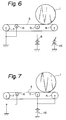
- the solenoid 9 is deenergized to retract the lever 10 and, therefore, the belt assembly including the belt 3 and rollers 4-7. As a result, the belt 3 is brought out of contact with the drum 1. This is to protect the drum 1 from deterioration while the transfer of a toner image is not performed.
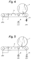
- FIG. 6 shows a fourth embodiment of the present invention which is similar to the third embodiment except for a variable power source 15 substituted for the power source 14.
- the variable power source 15 applies a bias voltage lower than the bias voltage to the bias roller 5 to the bias roller 4 and at the same time as the voltage to the bias roller 5.
- the power source 15 applies the same bias voltage as applied to the bias roller 5 to the bias roller 4.
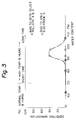
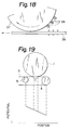
- the resulting potential distribution of the belt 3 is shown in FIG. 20.
- the CPU 27 causes the power source 14 to start applying the bias voltage to the bias roller 4 at the same time as the power source 8 applies the bias voltage to the bias roller 5 via the load driver 31.
- the bias rollers 4 and 5 inject charges into the sheet.
- the toner image is stably transferred to the sheet at the rear of the leading end portion of the belt 3. So long as the humidity is lower than 70 %, the separation of the sheet from the drum 1 is satisfactory. Since the bias rollers 4 and 5 sequentially deposit a charge on the sheet, the toner image is stably transferred from the leading edge toward the trailing edge of the sheet at all times.
- the color image sensor 109 is made up of blue (B), green (G) and red (R) color separating means and a CCD array or similar photoelectric transducer so as to read the three different colors at the same time.
- B, G and R image signals from the image sensor 109 are converted to black (BK), cyan (C), magenta (M) and yellow (Y) color image data by an image processor, not shown, on the basis of their intensity levels.
- the drum 112 is rotated and has the surface thereof uniformly charged by the main charger 121.
- the color scanner 101 starts reading the document 103 to produce BK image data.
- the unit 111 scans the charged surface of the drum 112 by a laser beam to electrostatically form a latent image thereon.
- the latent image derived from the BK image data be referred to as a BK latent image.
- latent images resulting from C, M and Y image data be referred to as a C latent image, an M latent image, and a Y latent image, respectively.
- the developer on the sleeve 126a is brought to the inoperative position. This is completed after the trailing edge of the Y image has reached the Y developing unit 126.
- the Y toner image formed on the drum 112 is transferred to the surface of the belt 128 being driven at the same speed as the drum 112.
- the belt 128 may be moved in any one of the following three modes or any combination thereof (matching the copy size).
- bias rollers 129 and 130 may each be provided with a desired reference potential which sets up the potential lower than 300 V between, the bias roller 129 and the contact point A, if desired.
- FIG. 28 shows another alternative embodiment which is similar to the embodiment of FIG. 27 except that the bias roller 129 is electrically floating, and that a roller 151 is held in contact with the belt 128 at a position upstream of the bias roller 129.
- the roller 151 is connected to ground.
- the bias roller 129 increases the potential at the contact point A when electrically floating as illustrated than when connected to ground, it is possible to lower the transfer voltage to be applied to the bias roller 130.
- the present invention provides an Image forming apparatus having various unprecedented advantages, as enumerated below
Landscapes
- Physics & Mathematics (AREA)
- General Physics & Mathematics (AREA)
- Electrostatic Charge, Transfer And Separation In Electrography (AREA)
- Control Or Security For Electrophotography (AREA)
- Color Electrophotography (AREA)
- Fax Reproducing Arrangements (AREA)
- Decoration By Transfer Pictures (AREA)
- Combination Of More Than One Step In Electrophotography (AREA)
Applications Claiming Priority (9)
| Application Number | Priority Date | Filing Date | Title |
|---|---|---|---|
| JP88916/92 | 1992-04-09 | ||
| JP8891692 | 1992-04-09 | ||
| JP8891692 | 1992-04-09 | ||
| JP9070192 | 1992-04-10 | ||
| JP9070192 | 1992-04-10 | ||
| JP90701/92 | 1992-04-10 | ||
| JP1015993 | 1993-01-25 | ||
| JP10159/93 | 1993-01-25 | ||
| JP01015993A JP3271811B2 (ja) | 1992-04-09 | 1993-01-25 | 画像形成装置 |
Publications (3)
| Publication Number | Publication Date |
|---|---|
| EP0568829A2 true EP0568829A2 (fr) | 1993-11-10 |
| EP0568829A3 EP0568829A3 (fr) | 1995-05-10 |
| EP0568829B1 EP0568829B1 (fr) | 2001-08-16 |
Family
ID=27278864
Family Applications (1)
| Application Number | Title | Priority Date | Filing Date |
|---|---|---|---|
| EP93105767A Expired - Lifetime EP0568829B1 (fr) | 1992-04-09 | 1993-04-07 | Appareil de formation d'images |
Country Status (5)
| Country | Link |
|---|---|
| EP (1) | EP0568829B1 (fr) |
| JP (1) | JP3271811B2 (fr) |
| KR (1) | KR0145748B1 (fr) |
| DE (1) | DE69330579T2 (fr) |
| ES (1) | ES2161701T3 (fr) |
Cited By (2)
| Publication number | Priority date | Publication date | Assignee | Title |
|---|---|---|---|---|
| EP0827043A3 (fr) * | 1996-08-29 | 1998-05-13 | Sharp Kabushiki Kaisha | Dispositif de transfert |
| EP1429207A3 (fr) * | 2002-09-19 | 2004-09-22 | Ricoh Company | Dispositif d'entraínement de bande, dispositif d'entraínement, procede et appareil de formation d'images. |
Families Citing this family (3)
| Publication number | Priority date | Publication date | Assignee | Title |
|---|---|---|---|---|
| JP3488328B2 (ja) * | 1996-02-02 | 2004-01-19 | 株式会社リコー | 転写ベルト装置 |
| JP2006047707A (ja) * | 2004-08-05 | 2006-02-16 | Ricoh Co Ltd | 画像形成方法及び画像形成装置 |
| JP5564993B2 (ja) * | 2010-03-01 | 2014-08-06 | 株式会社リコー | 画像形成装置 |
Family Cites Families (6)
| Publication number | Priority date | Publication date | Assignee | Title |
|---|---|---|---|---|
| JPS58111960A (ja) * | 1981-12-25 | 1983-07-04 | Ricoh Co Ltd | 転写紙分離装置 |
| JPH0623900B2 (ja) * | 1986-03-03 | 1994-03-30 | ヤマウチ株式会社 | 画像形成装置において使用される転写ベルト |
| JPH02110586A (ja) * | 1988-10-20 | 1990-04-23 | Canon Inc | 画像形成装置 |
| US5172173A (en) * | 1988-09-01 | 1992-12-15 | Canon Kabushiki Kaisha | Image forming device and transfer belt having contact-type electricity feeding means |
| DE68912889T2 (de) * | 1988-11-08 | 1994-08-25 | Canon Kk | Bilderzeugungsgerät mit Kontrollmitteln für die elektrostatische Anziehung von Übertragungsmaterial. |
| JPH03186876A (ja) * | 1989-12-16 | 1991-08-14 | Canon Inc | 画像形成装置 |
-
1993
- 1993-01-25 JP JP01015993A patent/JP3271811B2/ja not_active Expired - Lifetime
- 1993-04-07 DE DE69330579T patent/DE69330579T2/de not_active Expired - Lifetime
- 1993-04-07 ES ES93105767T patent/ES2161701T3/es not_active Expired - Lifetime
- 1993-04-07 EP EP93105767A patent/EP0568829B1/fr not_active Expired - Lifetime
- 1993-04-09 KR KR1019930005981A patent/KR0145748B1/ko not_active Expired - Lifetime
Cited By (5)
| Publication number | Priority date | Publication date | Assignee | Title |
|---|---|---|---|---|
| EP0827043A3 (fr) * | 1996-08-29 | 1998-05-13 | Sharp Kabushiki Kaisha | Dispositif de transfert |
| US5867760A (en) * | 1996-08-29 | 1999-02-02 | Sharp Kabushiki Kaisha | Transfer device with an anisotropin conductive layer |
| EP1429207A3 (fr) * | 2002-09-19 | 2004-09-22 | Ricoh Company | Dispositif d'entraínement de bande, dispositif d'entraínement, procede et appareil de formation d'images. |
| US7491142B2 (en) | 2002-09-19 | 2009-02-17 | Ricoh Company, Ltd. | Belt driving device, driving device, method, image forming apparatus |
| US8226510B2 (en) | 2002-09-19 | 2012-07-24 | Ricoh Company, Ltd. | Belt driving device, driving device, method, image forming apparatus |
Also Published As
| Publication number | Publication date |
|---|---|
| DE69330579D1 (de) | 2001-09-20 |
| EP0568829B1 (fr) | 2001-08-16 |
| DE69330579T2 (de) | 2002-06-27 |
| KR930022160A (ko) | 1993-11-23 |
| ES2161701T3 (es) | 2001-12-16 |
| JPH06167896A (ja) | 1994-06-14 |
| KR0145748B1 (ko) | 1998-09-15 |
| EP0568829A3 (fr) | 1995-05-10 |
| JP3271811B2 (ja) | 2002-04-08 |
Similar Documents
| Publication | Publication Date | Title |
|---|---|---|
| US5666622A (en) | Image transferring device and medium separating device for an image forming apparatus | |
| US4791452A (en) | Image forming apparatus having at least two-color image print function and method for controlling the same | |
| US5270783A (en) | Image forming equipment having improved toner sensing | |
| US6006062A (en) | Image transferring method using an intermediate transfer body and image forming apparatus for practicing the same | |
| US6163661A (en) | Electrostatic image forming apparatus capable of reducing defective image transfer caused by free toner particles deposited on a corona discharger | |
| US5276483A (en) | Image forming apparatus provided with an attraction charger controlled by one or more ambient conditions | |
| US5887218A (en) | Color image forming apparatus having toner and transfer sheet bearing members and image forming method thereof | |
| US6192205B1 (en) | Image forming apparatus | |
| JPH07210013A (ja) | 画像形成装置 | |
| EP0568829A2 (fr) | Appareil de formation d'images | |
| JP3526412B2 (ja) | 画像形成装置 | |
| US5923928A (en) | Dustless toner image transfer apparatus and method | |
| JP3461215B2 (ja) | 画像形成装置 | |
| EP0368617B1 (fr) | Appareil de formation d'images avec des moyens de contrôle de l'attraction électrostatique de matière de transfert | |
| US5812904A (en) | Image forming apparatus and method for controlling charging potential differently between image forming area and non-image forming area of photosensitive drum | |
| US7689152B2 (en) | Image forming apparatus with first and second transfer sections | |
| JPH1078689A (ja) | 画像形成装置 | |
| JP3844047B2 (ja) | 転写タイミング調整装置 | |
| JP3573439B2 (ja) | 画像形成装置 | |
| EP1310836B1 (fr) | Appareil de transfert | |
| JP2002139926A (ja) | 画像形成装置 | |
| JP3970592B2 (ja) | 画像形成装置 | |
| JP3423480B2 (ja) | 画像形成装置 | |
| JPH10142953A (ja) | 画像形成装置 | |
| JP3587955B2 (ja) | 静電画像形成方法 |
Legal Events
| Date | Code | Title | Description |
|---|---|---|---|
| PUAI | Public reference made under article 153(3) epc to a published international application that has entered the european phase |
Free format text: ORIGINAL CODE: 0009012 |
|
| 17P | Request for examination filed |
Effective date: 19930407 |
|
| AK | Designated contracting states |
Kind code of ref document: A2 Designated state(s): DE ES FR GB IT |
|
| PUAL | Search report despatched |
Free format text: ORIGINAL CODE: 0009013 |
|
| AK | Designated contracting states |
Kind code of ref document: A3 Designated state(s): DE ES FR GB IT |
|
| 17Q | First examination report despatched |
Effective date: 19960703 |
|
| GRAG | Despatch of communication of intention to grant |
Free format text: ORIGINAL CODE: EPIDOS AGRA |
|
| GRAG | Despatch of communication of intention to grant |
Free format text: ORIGINAL CODE: EPIDOS AGRA |
|
| GRAH | Despatch of communication of intention to grant a patent |
Free format text: ORIGINAL CODE: EPIDOS IGRA |
|
| GRAH | Despatch of communication of intention to grant a patent |
Free format text: ORIGINAL CODE: EPIDOS IGRA |
|
| GRAA | (expected) grant |
Free format text: ORIGINAL CODE: 0009210 |
|
| ITF | It: translation for a ep patent filed | ||
| AK | Designated contracting states |
Kind code of ref document: B1 Designated state(s): DE ES FR GB IT |
|
| REF | Corresponds to: |
Ref document number: 69330579 Country of ref document: DE Date of ref document: 20010920 |
|
| REG | Reference to a national code |
Ref country code: ES Ref legal event code: FG2A Ref document number: 2161701 Country of ref document: ES Kind code of ref document: T3 |
|
| ET | Fr: translation filed | ||
| REG | Reference to a national code |
Ref country code: GB Ref legal event code: IF02 |
|
| PLBE | No opposition filed within time limit |
Free format text: ORIGINAL CODE: 0009261 |
|
| 26N | No opposition filed | ||
| PGFP | Annual fee paid to national office [announced via postgrant information from national office to epo] |
Ref country code: ES Payment date: 20090513 Year of fee payment: 17 |
|
| PGFP | Annual fee paid to national office [announced via postgrant information from national office to epo] |
Ref country code: IT Payment date: 20090424 Year of fee payment: 17 |
|
| PGFP | Annual fee paid to national office [announced via postgrant information from national office to epo] |
Ref country code: GB Payment date: 20100325 Year of fee payment: 18 |
|
| PGFP | Annual fee paid to national office [announced via postgrant information from national office to epo] |
Ref country code: FR Payment date: 20100521 Year of fee payment: 18 |
|
| PGFP | Annual fee paid to national office [announced via postgrant information from national office to epo] |
Ref country code: DE Payment date: 20100430 Year of fee payment: 18 |
|
| PG25 | Lapsed in a contracting state [announced via postgrant information from national office to epo] |
Ref country code: IT Free format text: LAPSE BECAUSE OF NON-PAYMENT OF DUE FEES Effective date: 20100407 |
|
| REG | Reference to a national code |
Ref country code: ES Ref legal event code: FD2A Effective date: 20110715 |
|
| PG25 | Lapsed in a contracting state [announced via postgrant information from national office to epo] |
Ref country code: ES Free format text: LAPSE BECAUSE OF NON-PAYMENT OF DUE FEES Effective date: 20110705 |
|
| PG25 | Lapsed in a contracting state [announced via postgrant information from national office to epo] |
Ref country code: ES Free format text: LAPSE BECAUSE OF NON-PAYMENT OF DUE FEES Effective date: 20100408 |
|
| REG | Reference to a national code |
Ref country code: DE Ref legal event code: R119 Ref document number: 69330579 Country of ref document: DE |
|
| REG | Reference to a national code |
Ref country code: DE Ref legal event code: R119 Ref document number: 69330579 Country of ref document: DE |
|
| GBPC | Gb: european patent ceased through non-payment of renewal fee |
Effective date: 20110407 |
|
| REG | Reference to a national code |
Ref country code: FR Ref legal event code: ST Effective date: 20111230 |
|
| PG25 | Lapsed in a contracting state [announced via postgrant information from national office to epo] |
Ref country code: FR Free format text: LAPSE BECAUSE OF NON-PAYMENT OF DUE FEES Effective date: 20110502 |
|
| PG25 | Lapsed in a contracting state [announced via postgrant information from national office to epo] |
Ref country code: GB Free format text: LAPSE BECAUSE OF NON-PAYMENT OF DUE FEES Effective date: 20110407 |
|
| PG25 | Lapsed in a contracting state [announced via postgrant information from national office to epo] |
Ref country code: DE Free format text: LAPSE BECAUSE OF NON-PAYMENT OF DUE FEES Effective date: 20111031 |