EP0568835A1 - Elément de compensation pour tuyauteries à enveloppe en matière plastique - Google Patents
Elément de compensation pour tuyauteries à enveloppe en matière plastique Download PDFInfo
- Publication number
- EP0568835A1 EP0568835A1 EP93105846A EP93105846A EP0568835A1 EP 0568835 A1 EP0568835 A1 EP 0568835A1 EP 93105846 A EP93105846 A EP 93105846A EP 93105846 A EP93105846 A EP 93105846A EP 0568835 A1 EP0568835 A1 EP 0568835A1
- Authority
- EP
- European Patent Office
- Prior art keywords
- compensation element
- pipe
- element according
- tube
- medium pipe
- Prior art date
- Legal status (The legal status is an assumption and is not a legal conclusion. Google has not performed a legal analysis and makes no representation as to the accuracy of the status listed.)
- Granted
Links
Images




Classifications
-
- F—MECHANICAL ENGINEERING; LIGHTING; HEATING; WEAPONS; BLASTING
- F16—ENGINEERING ELEMENTS AND UNITS; GENERAL MEASURES FOR PRODUCING AND MAINTAINING EFFECTIVE FUNCTIONING OF MACHINES OR INSTALLATIONS; THERMAL INSULATION IN GENERAL
- F16L—PIPES; JOINTS OR FITTINGS FOR PIPES; SUPPORTS FOR PIPES, CABLES OR PROTECTIVE TUBING; MEANS FOR THERMAL INSULATION IN GENERAL
- F16L59/00—Thermal insulation in general
- F16L59/14—Arrangements for the insulation of pipes or pipe systems
- F16L59/153—Arrangements for the insulation of pipes or pipe systems for flexible pipes
-
- F—MECHANICAL ENGINEERING; LIGHTING; HEATING; WEAPONS; BLASTING
- F16—ENGINEERING ELEMENTS AND UNITS; GENERAL MEASURES FOR PRODUCING AND MAINTAINING EFFECTIVE FUNCTIONING OF MACHINES OR INSTALLATIONS; THERMAL INSULATION IN GENERAL
- F16L—PIPES; JOINTS OR FITTINGS FOR PIPES; SUPPORTS FOR PIPES, CABLES OR PROTECTIVE TUBING; MEANS FOR THERMAL INSULATION IN GENERAL
- F16L51/00—Expansion-compensation arrangements for pipe-lines
- F16L51/02—Expansion-compensation arrangements for pipe-lines making use of a bellows or an expansible folded or corrugated tube
- F16L51/025—Expansion-compensation arrangements for pipe-lines making use of a bellows or an expansible folded or corrugated tube with several corrugations
- F16L51/027—Expansion-compensation arrangements for pipe-lines making use of a bellows or an expansible folded or corrugated tube with several corrugations with external reinforcement
-
- F—MECHANICAL ENGINEERING; LIGHTING; HEATING; WEAPONS; BLASTING
- F16—ENGINEERING ELEMENTS AND UNITS; GENERAL MEASURES FOR PRODUCING AND MAINTAINING EFFECTIVE FUNCTIONING OF MACHINES OR INSTALLATIONS; THERMAL INSULATION IN GENERAL
- F16L—PIPES; JOINTS OR FITTINGS FOR PIPES; SUPPORTS FOR PIPES, CABLES OR PROTECTIVE TUBING; MEANS FOR THERMAL INSULATION IN GENERAL
- F16L59/00—Thermal insulation in general
- F16L59/14—Arrangements for the insulation of pipes or pipe systems
- F16L59/16—Arrangements specially adapted to local requirements at flanges, junctions, valves or the like
- F16L59/166—Arrangements specially adapted to local requirements at flanges, junctions, valves or the like covering the end of an insulated section
Definitions
- the invention relates to a compensation element for plastic jacket pipes for accommodating changes in length and direction due to thermal expansion, preferably in underground buried, in particular non-bendable jacket pipes, the compensation element consisting of a bendable jacket tube comprising an expansion space, a bendable medium pipe which is mounted radially and axially movable therein, and end pieces, and where surround the medium pipe with a heat insulation layer and / or the cladding pipe is lined with a heat insulation layer.
- the object of the invention is therefore to design a compensation element of the type mentioned in such a way that on the one hand there is sufficient support in the vertical direction, but on the other hand the medium pipe can carry out its movements caused by thermal expansion without any significant restoring forces.
- the bendable medium pipe is fixed radially and angularly only via its largely rigid end pieces with respect to the cladding pipe with its end pieces, and that the medium pipe is essentially freely movable within the cladding pipe in the area between these end pieces.
- the necessary movement possibilities within the cladding tube are released to the medium pipe, so that it can in particular only be bent into the required position at the construction site, with sufficient holding and guiding of the medium pipe being ensured via its end pieces.
- the medium pipe within the cladding pipe is therefore not subject to any constraints which prevent it from making the necessary movements due to thermal expansion while building up a restoring force.
- measures can easily be taken to guide and support the medium pipe with regard to its movements due to thermal expansion in a certain direction.
- the medium pipe can be provided with an axial support, which expediently consists of a braid covering of the medium pipe.
- the thermal insulation layer may be designed as a compressible insulating material with elastic resilient properties which completely fills the expansion space between the cladding tube and the medium tube.
- the medium pipe is thus free to move within the insulating material without any significant restoring forces being built up, the insulating material following the properties of the medium pipe due to its properties.
- thermal insulation layer of the medium pipe or the cladding pipe is provided with wear protection against the adjacent component.
- the medium pipe can move freely within the cladding pipe without the thermal insulation layer being impaired or worn over a long period of operation.
- the wear protection is a screw thread spiral made of metal or plastic that is applied to the thermal insulation layer or inserted therein. Such a helix then takes over the abrasion protection with respect to the neighboring component. It can be advantageous here that the helix is wound more tightly at points of contact between the medium pipe and the cladding pipe than over its further length range in order to be able to develop a special protective effect at this point.
- the heat insulation layer of the cladding tube or the medium tube is formed by rings which are in engagement with one another in the form of scales, and that the rings are equipped with wear protection on their surface facing the adjacent component.
- the medium pipe is guided in the radial direction of an arc of the compensation element or of the cladding tube.
- the free mobility of the medium pipe is directed in a certain direction, namely in the direction in which the maximum freedom of movement is available for the medium pipe within the cladding pipe.
- At least one link part is placed on the medium pipe in the region of the apex of a cladding tube arch, which is slidably guided in a backdrop, through a bracket inserted into the cladding tube in the radial direction of the arc walking legs is formed.
- the medium pipe is prevented from evasive movements transversely to the maximum freedom of movement within the cladding pipe, so that it can follow thermal expansion-related displacement tendencies in an optimal manner without any restoring forces being built up.
- the medium pipe if appropriate together with the heat insulation enveloping it, is mounted so as to be displaceable in the radial direction of an arc on a support with a sliding surface inserted into the casing pipe.
- a link part is inserted into the cladding tube, at least in the region of an arc, over the edges of which in the radial direction of the arc, the carrier tube is slidably guided.
- strips of metal or the like which are bendable only in the bending plane, are preferably attached to the medium pipe via its longitudinal extension, on both sides of the medium pipe. Such strips carry and guide the carrier pipe and thereby prevent its expansion due to thermal expansion in a direction deviating from the bending plane.
- a radially directed spacer made of wear-resistant material with a radial extension bridging the thermal insulation layer is inserted at least in the region of the apex of an arc on the carrier pipe or in the cladding pipe.
- a such a spacer supports the adjacent, mutually movable components while protecting the intermediate thermal insulation layer.
- a contact ring is rotatably arranged around the spacer in order to counteract clamping forces that build up in the circumferential direction of the cladding tube or medium tube during the thermal expansion-related movement of the medium tube .
- the cladding tube has an oval cross-section in the region of an arch with the position of the larger cross-sectional axis in the radial direction of the arch.
- a space and material reduction of the compensation element is hereby achieved without the necessary or optimal, thermal expansion-related freedom of movement of the medium pipe being restricted.
- the respective end piece of the medium pipe is a piece of plastic jacket pipe with an inner steel pipe, a surrounding thermal insulation layer made of composite foam and an outer plastic jacket, so that the connection to the further lines can be made without any particular problems.
- the annular space between the steel tube and the plastic jacket has an additional stiffening.
- This stiffening can be formed by at least one essentially radially directed support body which is expediently inserted at the end of the respective end piece facing the media tube.
- the support body consists of tubular sleeves, each parallel to the steel tube and plastic jacket, and that the tubular sleeves are connected to one another by radial webs, it being sufficient for at least three webs to be arranged uniformly distributed over the circumference of the tubular sleeves.
- the tube sleeves are designed in a cutting shape on their side facing away from the medium tube, so that they can be easily pressed into the space between the steel tube and the plastic jacket.
- stiffening is provided by solid bodies integrated in the thermal insulation layer, that is to say the insulation layer as a whole is given a higher resistance.
- Fig. 1 shows a compensation element designated overall by 1. This has a cladding tube 2 with rigid end pieces 3, 3 ', the cladding tube 2 being designed as a bendable cladding tube, for example in the form of a corrugated tube or a wound tube.
- a medium pipe 4 is arranged inside the cladding pipe.
- the medium pipe 4 is surrounded by a heat insulation layer 5 and, moreover, is also designed as a flexible conduit element in the form of a corrugated hose, winding hose or the like. To support axial forces occurring on the medium pipe, the latter is also surrounded by a braided hose 6 within the thermal insulation layer 5.
- the medium pipe 4 has end pieces 7, 7 ', which are designed as plastic jacket pipe pieces and an inner steel pipe 8, 8 ', a surrounding thermal insulation layer 9, 9' made of composite foam and an outer plastic jacket 10, 10 '.
- the end pieces 7, 7 'of the medium pipe 4 are guided axially displaceably within the end pieces 3, 3' of the cladding pipe 2. With the end pieces 7, 7 'designed as plastic jacket pipe pieces, the compensation element is connected to further plastic jacket pipe lines, not shown.
- the medium pipe 4 assumes 2 different positions depending on the existing temperature load and depending on the position of the end pieces 7, 7 ′ due to thermal expansion, the lower left half in FIG. 1 assuming the position of the medium pipe 4 cold state and the upper right half shows the position of the medium pipe 4 when warm.
- This illustration also makes it clear that, due to thermal expansion, the medium pipe 4 essentially executes a movement within the arc of curvature given by the compensation element 1, which runs with respect to the arc of curvature in its radial direction and takes up the most space in this direction. Therefore, the arc of curvature of the compensation element is appropriately aligned during manufacture or installation so that the medium pipe 4 lies in the cold state on the inside of the cladding tube 2 forming the arc.
- the medium pipe 4 is freely movable within the cladding tube 2 between its end pieces 7, 7 ', so there is in particular not subject to any constraints building up a restoring force.
- the medium pipe 4 shows a short part of the medium pipe 4 in an axial half section, the braid covering 6 and the thermal insulation layer 5 surrounding it being visible.
- the medium pipe 4 is designed in the present case as a corrugated hose.
- the heat insulation layer 5 is surrounded with wear protection in the form of a helical coil 12, which finally comes into contact with the cladding tube 2 according to FIG. 1 and thereby prevents the heat insulation layer 5 from being rubbed off or otherwise impaired when the medium tube 4 moves.
- wear protection in the form of a helical coil 12, which finally comes into contact with the cladding tube 2 according to FIG. 1 and thereby prevents the heat insulation layer 5 from being rubbed off or otherwise impaired when the medium tube 4 moves.
- the helical thread helix 12 is wound more closely there, as can be seen from FIG. 3 at 13.
- thermal insulation layer 5 by means of rings 14 which are in the form of scales and which are provided with wear protection 15 on their surface facing the neighboring component, in the present case the cladding tube 2, which in the The present case consists of rings placed on the outside of the rings 14 or inserted therein into rings made of metal or another wear-resistant material.
- Fig. 4 shows clearly only in a simplified, fragmentary form, the structure of the thermal insulation layer 5 while omitting the medium pipe 4 arranged therein together with its braiding 6.
- the individual rings 14 are brought together by serpentine spring elements 16 in order to to be able to work against one another in the axial direction when the medium pipe 4 is curved.
- FIG. 5 shows an example of a cladding tube 2 lined with a thermal insulation layer 17 and a helical helix 18 inserted into the thermal insulation layer 17, against which the medium tube 4 with its braiding 6 is movable and in contact.
- FIGS. 6 to 9 show an object comparable to FIGS. 2 to 4, reference being made to the above description using the previous reference numerals to avoid repetition.
- Fig. 6 shows in particular the compensation element 1 in the region of the end pieces 3, 3 ', 7, 7', it being apparent that the cladding tube 2 via a sealing connection 20 on the plastic jacket 10, 10 'of the end pieces 7, 7 'sits.
- a sleeve 23 is drawn over the thermal insulation layer 5 of the medium tube 4, outside of which a screw helix 24 is arranged, which with regard to the structure and effect of the screw helix 12 according to FIGS. 2 to 4 corresponds.
- the gears of a supporting spiral 25 are arranged between the revolutions of the spiral coil 24 within the collar 23 and hold the collar 23 on the external format of the thermal barrier layer 5 .
- FIG. 7 again shows a radial section of the carrier pipe as shown on the right in FIG. 6.
- FIG. 8 shows an external view.
- FIG. 9 shows the external view of the object according to FIG. 6 supplemented over the entire arc of the compensation element, it being particularly evident that the cladding tube 2 is designed as a corrugated tube or corrugated tube.
- a link part 30 is placed on the medium pipe 4 - of course including its braided casing - at least in the area of the middle of the curve shown in FIG. 1, which is slidably guided in a link 31, which through a into the cladding tube 2 inserted bracket is formed with leg 32 extending in the radial direction of the arc.
- the medium pipe 4 is guided in the radial direction of the curve shown in FIG. 1 along the legs 32 cleanly without the thermal insulation layer 5 could be impaired and without restoring forces with respect to the thermal expansion-related movements of the medium pipe 4 could occur.
- the object according to FIG. 11 is based on the same idea.
- the medium pipe 4, together with its thermal insulation layer 5, is slidably mounted in the radial direction of the bend according to FIG.
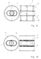
- a thermal insulation layer 17 (see comparatively FIG. 5) is arranged inside the cladding tube 2, which is interrupted by link parts 40 arranged at an axial distance, which in the radial direction of the arc shown in FIG. 1 have an oval guide opening 42 form within which the medium pipe 4 can slide together with its braiding 6 in the radial direction of the bend shown in FIG. 1.
- brackets 45 are arranged within the thermal insulation layer 17, which take over the guiding of the medium pipe 4 in accordance with the link parts 40 from FIG. 12.
- FIG. 14 A different variant is shown in FIG. 14.
- the medium pipe 4 is equipped with clamps 50, which are connected to one another in the bending plane according to FIG. 1 of the medium pipe 4 by means of flexible strips or strips 51, which ensure that the medium pipe 4 is only in Radial direction of the arc shown in FIG. 1 of the compensation element 1 can move. In this way, any contact between the cladding tube 2 and the thermal insulation layer 5 of the medium tube 4 is avoided as long as these parts do not collide in the extreme positions due to their movements due to thermal expansion.
- FIG. 15 shows a further variant in that spacer disks 60, which sit radially inward on the medium pipe 4, are inserted into the thermal insulation layer 5 of the medium pipe 4 at axial intervals.
- These spacers can be made of wear-resistant material and thus protect the thermal insulation layer 5 against wear when the medium pipe 4 moves due to thermal expansion.
- the spacers can be surrounded on the outside in the manner shown here in a simplified manner by contact rings 61 which are rotatably arranged on the spacers 60.
- FIG. 16 shows a possibility of saving space and reducing costs, which is generally applicable to all of the above embodiments, in that the cladding tube 2 in the region of the bend shown in FIG. 1 and also in FIG. 16 is designed as a tube with an oval cross section, the position the larger cross-sectional axis is arranged in the radial direction of the arc.
- the section BB shows in particular, the necessary, thermal expansion-related freedom of movement is created for the medium pipe 4 without, on the other hand, the cladding tube 2 taking up unnecessary space in addition to this freedom of movement.
- FIGS. 17 and 18 show, on the basis of an end section of the compensation element, which corresponds to the left end of the illustration in FIG. 6, two further objects which improve its use properties in the context of the new compensation element.
- the reference numbers already used are used again, as far as comparable parts recur.
- FIG. 17 shows that a support body 70 for mutual radial support of steel pipe 8, 8 'and plastic jacket 10, 10' is inserted into the end face of the end piece 7, 7 'facing the medium pipe 4.
- This support body consists of tubular sleeves 71 and 72, each parallel to the steel tube and plastic jacket, which are connected to one another by radial webs 73, in the present case four webs being arranged evenly distributed over the circumference.
- the radial distance between steel tube 8, 8 'and plastic jacket 10, 10' is stiffened, so that when the compensation element is bent the thermal barrier coating 9, 9 'cannot be deformed.
- the tube sleeves 71, 72 are chamfered on their side facing away from the medium tube 4 in order to facilitate assembly.
- FIG. 18 Another possible way of improving the support between the steel pipe 8, 8 'and the plastic jacket 10, 10' is shown in FIG. 18.
- the heat insulation layer 9, 9 ' is provided with solid bodies 74 integrated into the material, which give the heat insulation layer a higher strength, whereby the increase in strength can be controlled via the amount of integrated solids 74.
- stiffening can also be carried out by choosing a suitable, inherently firmer material for the heat insulation layer 9, 9 '.
Landscapes
- Engineering & Computer Science (AREA)
- General Engineering & Computer Science (AREA)
- Mechanical Engineering (AREA)
- Thermal Insulation (AREA)
- Rigid Pipes And Flexible Pipes (AREA)
- Sampling And Sample Adjustment (AREA)
Applications Claiming Priority (2)
| Application Number | Priority Date | Filing Date | Title |
|---|---|---|---|
| DE4214883A DE4214883A1 (de) | 1992-05-05 | 1992-05-05 | Kompensationselement für Kunststoffmantelrohrleitungen |
| DE4214883 | 1992-05-05 |
Publications (2)
| Publication Number | Publication Date |
|---|---|
| EP0568835A1 true EP0568835A1 (fr) | 1993-11-10 |
| EP0568835B1 EP0568835B1 (fr) | 1996-10-23 |
Family
ID=6458246
Family Applications (1)
| Application Number | Title | Priority Date | Filing Date |
|---|---|---|---|
| EP93105846A Expired - Lifetime EP0568835B1 (fr) | 1992-05-05 | 1993-04-08 | Elément de compensation pour tuyauteries à enveloppe en matière plastique |
Country Status (3)
| Country | Link |
|---|---|
| EP (1) | EP0568835B1 (fr) |
| AT (1) | ATE144601T1 (fr) |
| DE (2) | DE4214883A1 (fr) |
Cited By (4)
| Publication number | Priority date | Publication date | Assignee | Title |
|---|---|---|---|---|
| US6554321B1 (en) * | 1999-07-12 | 2003-04-29 | Hutchinson | Decoupling sleeve for mounting in a motor vehicle exaust pipe |
| EP2045451A2 (fr) | 2007-10-01 | 2009-04-08 | BDD Beteiligungs GmbH | Dispositif d'isolation d'un compensateur |
| CN104879598A (zh) * | 2015-05-29 | 2015-09-02 | 扬中市第一蝶阀厂有限公司 | 一种改进型风箱竖井膨胀节 |
| CN104358969B (zh) * | 2014-11-19 | 2017-07-28 | 广东美的环境电器制造有限公司 | 导气管和衣物护理机 |
Families Citing this family (1)
| Publication number | Priority date | Publication date | Assignee | Title |
|---|---|---|---|---|
| DE102024120587A1 (de) * | 2024-07-19 | 2026-01-22 | VALAND Enterprises Inc. Niederlassung Deutschland | Rohrleitung, Rohrsystem, Wärmenetz und Verfahren zur Herstellung einer Rohrleitung |
Citations (3)
| Publication number | Priority date | Publication date | Assignee | Title |
|---|---|---|---|---|
| DE438654C (de) * | 1926-12-22 | Saechsische Maschinenfabrik Vo | Kompensator fuer Rohrleitungen | |
| US4519634A (en) * | 1982-12-22 | 1985-05-28 | Hand James D | Transition pipe fitting |
| DE3934256A1 (de) * | 1988-10-14 | 1990-04-19 | Architektur Bauwesen Hochschul | Biegbares, waermegedaemmtes mantelrohrbauteil |
Family Cites Families (4)
| Publication number | Priority date | Publication date | Assignee | Title |
|---|---|---|---|---|
| DE7513053U (de) * | 1975-09-18 | Wsw Stahl Und Wasserbau Gmbh | Leitungsrohr mit Eckstück | |
| DE1968892U (de) * | 1967-07-19 | 1967-09-21 | Mannesmann Ag | Rohrkruemmer fuer waermeisolierte rohrleitungen. |
| DE2257699C3 (de) * | 1972-11-21 | 1975-10-09 | Brown Boveri-Sulzer Turbomaschinen Ag, Zuerich (Schweiz) | Gekrümmtes Rohrleitungsstück |
| DD116669A1 (fr) * | 1975-01-09 | 1975-12-05 |
-
1992
- 1992-05-05 DE DE4214883A patent/DE4214883A1/de not_active Ceased
-
1993
- 1993-04-08 DE DE59304243T patent/DE59304243D1/de not_active Expired - Lifetime
- 1993-04-08 EP EP93105846A patent/EP0568835B1/fr not_active Expired - Lifetime
- 1993-04-08 AT AT93105846T patent/ATE144601T1/de not_active IP Right Cessation
Patent Citations (3)
| Publication number | Priority date | Publication date | Assignee | Title |
|---|---|---|---|---|
| DE438654C (de) * | 1926-12-22 | Saechsische Maschinenfabrik Vo | Kompensator fuer Rohrleitungen | |
| US4519634A (en) * | 1982-12-22 | 1985-05-28 | Hand James D | Transition pipe fitting |
| DE3934256A1 (de) * | 1988-10-14 | 1990-04-19 | Architektur Bauwesen Hochschul | Biegbares, waermegedaemmtes mantelrohrbauteil |
Cited By (5)
| Publication number | Priority date | Publication date | Assignee | Title |
|---|---|---|---|---|
| US6554321B1 (en) * | 1999-07-12 | 2003-04-29 | Hutchinson | Decoupling sleeve for mounting in a motor vehicle exaust pipe |
| EP2045451A2 (fr) | 2007-10-01 | 2009-04-08 | BDD Beteiligungs GmbH | Dispositif d'isolation d'un compensateur |
| EP2045451A3 (fr) * | 2007-10-01 | 2010-01-27 | BDD Beteiligungs GmbH | Dispositif d'isolation d'un compensateur |
| CN104358969B (zh) * | 2014-11-19 | 2017-07-28 | 广东美的环境电器制造有限公司 | 导气管和衣物护理机 |
| CN104879598A (zh) * | 2015-05-29 | 2015-09-02 | 扬中市第一蝶阀厂有限公司 | 一种改进型风箱竖井膨胀节 |
Also Published As
| Publication number | Publication date |
|---|---|
| DE59304243D1 (de) | 1996-11-28 |
| DE4214883A1 (de) | 1993-11-11 |
| ATE144601T1 (de) | 1996-11-15 |
| EP0568835B1 (fr) | 1996-10-23 |
Similar Documents
| Publication | Publication Date | Title |
|---|---|---|
| EP0210271B1 (fr) | Tuyau ondule flexible avec ondes annulaires paralleles les unes aux autres et support axial | |
| EP0856648B1 (fr) | Elément de conduite flexible pour conduites de gaz d'échappement | |
| DE3610684A1 (de) | Gelenkige verbindung von rohrteilen, insbesondere bei abgasleitungen von kraftfahrzeugen | |
| EP1048881B1 (fr) | Conduite de produit réfrigérant pour conditionneurs d'air | |
| EP0458011B1 (fr) | Elément de conduite, en particulier pour tuyau d'échappement des moteurs à combustion interne | |
| DE9207276U1 (de) | Kompensationselement für Kunststoffmantelrohrleitungen | |
| EP0568835B1 (fr) | Elément de compensation pour tuyauteries à enveloppe en matière plastique | |
| DE19533627C1 (de) | Axialkompensator zur Aufnahme von Rohrleitungsdehnungen | |
| EP0108829A1 (fr) | Compensateur axial | |
| DE3506626A1 (de) | Flexibles abgasrohr fuer ein kraftfahrzeug | |
| EP0229345B1 (fr) | Dispositif de connexion élastique de deux tuyaux à paroi double | |
| DE3643038C2 (fr) | ||
| DE4029523C1 (fr) | ||
| EP0436772A2 (fr) | Elément de conduite en forme du tuyau ondulé ou soufflet | |
| EP0985115B1 (fr) | Compensateur axial | |
| DE2811015A1 (de) | Vorrichtung zum kontinuierlichen transportieren und biegen von glasscheiben | |
| EP0568813B1 (fr) | Elément de construction pour l'isolation thermique de bâtiments | |
| EP1507997B1 (fr) | Dispositif servant a compenser des variations de longueur dans un systeme de canalisations | |
| DE3409193A1 (de) | Biegsamer betaetigungszug | |
| DE3544712A1 (de) | Verbindung zweier teile einer leitung durch einen balg oder ein wellrohr | |
| DE8535523U1 (de) | Verbindung zweier Teile einer Leitung durch einen Balg oder ein Wellrohr | |
| DE19826950C1 (de) | Schutzrohr für eine Versorgungsleitung | |
| DE3042310C2 (de) | Leitungselement in Form eines ringgewellten Schlauches oder Balges | |
| EP1522783B1 (fr) | Construction d'isolation et procédé de réalisation d'une construction d'isolation et éléments correspondants | |
| DE3544884C2 (de) | Biegbarer Hochdruck-Metall-Ringwellschlauch |
Legal Events
| Date | Code | Title | Description |
|---|---|---|---|
| PUAI | Public reference made under article 153(3) epc to a published international application that has entered the european phase |
Free format text: ORIGINAL CODE: 0009012 |
|
| AK | Designated contracting states |
Kind code of ref document: A1 Designated state(s): AT BE CH DE DK LI NL |
|
| 17P | Request for examination filed |
Effective date: 19931209 |
|
| 17Q | First examination report despatched |
Effective date: 19941110 |
|
| GRAG | Despatch of communication of intention to grant |
Free format text: ORIGINAL CODE: EPIDOS AGRA |
|
| GRAH | Despatch of communication of intention to grant a patent |
Free format text: ORIGINAL CODE: EPIDOS IGRA |
|
| GRAH | Despatch of communication of intention to grant a patent |
Free format text: ORIGINAL CODE: EPIDOS IGRA |
|
| GRAA | (expected) grant |
Free format text: ORIGINAL CODE: 0009210 |
|
| AK | Designated contracting states |
Kind code of ref document: B1 Designated state(s): AT BE CH DE DK LI NL |
|
| PG25 | Lapsed in a contracting state [announced via postgrant information from national office to epo] |
Ref country code: NL Free format text: LAPSE BECAUSE OF FAILURE TO SUBMIT A TRANSLATION OF THE DESCRIPTION OR TO PAY THE FEE WITHIN THE PRESCRIBED TIME-LIMIT Effective date: 19961023 Ref country code: DK Effective date: 19961023 |
|
| REF | Corresponds to: |
Ref document number: 144601 Country of ref document: AT Date of ref document: 19961115 Kind code of ref document: T |
|
| REF | Corresponds to: |
Ref document number: 59304243 Country of ref document: DE Date of ref document: 19961128 |
|
| NLV1 | Nl: lapsed or annulled due to failure to fulfill the requirements of art. 29p and 29m of the patents act | ||
| PG25 | Lapsed in a contracting state [announced via postgrant information from national office to epo] |
Ref country code: AT Free format text: LAPSE BECAUSE OF NON-PAYMENT OF DUE FEES Effective date: 19970408 |
|
| PGFP | Annual fee paid to national office [announced via postgrant information from national office to epo] |
Ref country code: DE Payment date: 19970423 Year of fee payment: 5 |
|
| PG25 | Lapsed in a contracting state [announced via postgrant information from national office to epo] |
Ref country code: LI Free format text: LAPSE BECAUSE OF NON-PAYMENT OF DUE FEES Effective date: 19970430 Ref country code: CH Free format text: LAPSE BECAUSE OF NON-PAYMENT OF DUE FEES Effective date: 19970430 Ref country code: BE Effective date: 19970430 |
|
| PLBE | No opposition filed within time limit |
Free format text: ORIGINAL CODE: 0009261 |
|
| 26N | No opposition filed | ||
| REG | Reference to a national code |
Ref country code: CH Ref legal event code: PL |
|
| PG25 | Lapsed in a contracting state [announced via postgrant information from national office to epo] |
Ref country code: DE Free format text: LAPSE BECAUSE OF THE APPLICANT RENOUNCES Effective date: 19980131 |