EP0568846A1 - Réducteur d'erreur de quantification pour des signaux audio - Google Patents
Réducteur d'erreur de quantification pour des signaux audio Download PDFInfo
- Publication number
- EP0568846A1 EP0568846A1 EP93106167A EP93106167A EP0568846A1 EP 0568846 A1 EP0568846 A1 EP 0568846A1 EP 93106167 A EP93106167 A EP 93106167A EP 93106167 A EP93106167 A EP 93106167A EP 0568846 A1 EP0568846 A1 EP 0568846A1
- Authority
- EP
- European Patent Office
- Prior art keywords
- filter
- signal
- noise
- characteristic
- quantizing
- Prior art date
- Legal status (The legal status is an assumption and is not a legal conclusion. Google has not performed a legal analysis and makes no representation as to the accuracy of the status listed.)
- Granted
Links
Images


Classifications
-
- G—PHYSICS
- G11—INFORMATION STORAGE
- G11B—INFORMATION STORAGE BASED ON RELATIVE MOVEMENT BETWEEN RECORD CARRIER AND TRANSDUCER
- G11B20/00—Signal processing not specific to the method of recording or reproducing; Circuits therefor
- G11B20/10—Digital recording or reproducing
- G11B20/10527—Audio or video recording; Data buffering arrangements
-
- H—ELECTRICITY
- H04—ELECTRIC COMMUNICATION TECHNIQUE
- H04B—TRANSMISSION
- H04B14/00—Transmission systems not characterised by the medium used for transmission
- H04B14/02—Transmission systems not characterised by the medium used for transmission characterised by the use of pulse modulation
- H04B14/04—Transmission systems not characterised by the medium used for transmission characterised by the use of pulse modulation using pulse code modulation
- H04B14/046—Systems or methods for reducing noise or bandwidth
Definitions
- This invention relates to a quantizing error reducer for an audio signal, which is constructed to reduce a quantizing error generated in quantization of an audio signal.
- digital audio equipments for handling audio signals in a digital form there exist, e.g., players for so called compact discs (CD) and/or so called digital audio tape recorders (DATs), etc.
- various unified standard requirements are prescribed. For example, in the case of the bit length of digital audio signals handled in these equipments, it is prescribed from the above unified standard requirements that such audio signals have a bit length of 16 bits.
- digital audio signals in these digital audio equipments there are used digital audio signals obtained by encoding analog audio signals (sound waveform signals) by using a simple linear quantization like, e.g., so called PCM (linear pulse coding).
- PCM linear pulse coding
- a processing system to reduce a quantizing error by a so called error feedback, to feed a quantizing error (quantaing noise or quantizing distortion) generated by a quantizer in quantizing an audio signal back to the input side of the quantizer through a noise filter.
- a quantizing error quantaing noise or quantizing distortion
- the quantizing distortion in the linear quantization like the above-described PCM coding has a frequency characteristic flat over the entire frequency band of an audio signal.
- the ear of the human being has a difference in the hearing sensitivity depending upon a frequency of sound, it can not be said that the quantizing error reducing processing by the error feed back is necessarily effective in view of hearing sense.
- This invention has been proposed with the actual circumstances as described in view, and its object is to provide a quantizing error reducer for an audio signal, which is capable of reducing a quantizing error (quantizing noise) effectively from a viewpoint of hearing sense.
- a quantizing error reducer has been proposed in order to attain the above-described object.
- the input signal is first conditioned by adding to it a dither signal. Then, a quantizing error generated in a quantizer is fed back to the input side of the quantizer through a noise filter.
- the filter coefficient of the noise filter is set on the basis of information relating to an equi-loudness curve corresponding to the hearing sense characteristic of the human being.
- an approach is employed to feed a quantizing error back to the input side of the quantizer through the noise filter of which coefficient is set on the basis of information relating to the equi-loudness curve, thereby making it possible to reduce a quantizing error in a frequency band of a sound easy to be heard. Accordingly, it is possible to reduce noises in the hearing sense thus to improve the dynamic range in the hearing sense.
- FIG. 1 there is shown, in a block form, the outline of the configuration of a quantizing error reducer for an audio signal of the first embodiment.
- a quantizing error generated in a quantizer 11 is fed back to the input side of the quantizer 11 through a noise filter 13.
- the filter coefficient of the noise filter 13 is set on the basis of information relating to so called an equi-loudness curve RC as shown in FIG. 2 corresponding to the hearing sense characteristic of the human being.
- a digital audio signal obtained by sampling at an arbitrary sampling frequency is delivered to the input terminal 1 of FIG. 1.
- the digital audio signal is combined wit h a dither signal generated by a dither generator 21, is then re-quantized at the quantizer 11, and is finally outputted from the output terminal 2.
- the quantization error reducer of this embodiment (and similarly the following embodiments, to be described later) consists of two subsystems, namely the dither subsystem and the noise-shaping subsystem. These subsystems have complementary effects, and their characteristics can be varied independently.
- the dither subsystem consists of a level detector 20, a dither generator 21 and an adder 10.
- the dither signal generated by the dither generator 21 is added to the input signal by the adder 10.
- the purpose of the dither subsystem is to generate a so called dither signal, defined as a random or pseudo-random signal which is added to the input signal before quantization such that signal correlation between the quantization error and the input signal is reduced.
- the dither is generated by a dither generator 21.
- the spectral nature of this dither signal depends on the specific implementation of the embodiment and is determined by the characteristics of the class of input signals to be processed.
- Typical dither spectra include so called white dither (equal at all frequencies) which produces theoretically optimal decorrelation, so called high-frequency dither which has its energy concentrated in inaudible ranges of the signal spectrum thus further reducing noise in the hearing sense, and all-zero dither (equivalent to no dither at all) which is appropriate when the input signal is already sufficiently random such that no further decorrelation is required.
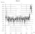
- the power spectrum of an undithered sine wave of 1-bit amplitude is shown in FIG. 17; the error correlation is shown by the harmonic spectral peaks.
- the same signal quantized with white dither is shown in FIG. 18; there is only one spectral peak, showing that the quantization error is not correlated with the signal.
- FIG. 19 shows the same signal quantized with high-frequency dither; although the dither power is greater, the dither will be less audible because it is concentrated in regions where the ear is insensitive.
- a level detector 20 may be used to control either the type of dither generated by the dither generator 21, or the level of said dither, or both. For example, it is inappropriate to add dither to an input signal consisting of all zeros; this condition can therefore be detected by the level detector 20 and the dither generator controlled appropriately. Further, low-level input signals often require more dither than high-level signals; the level of the dither may therefore be gradually reduced as the signal level increase s.
- the quantization error is reduced by the noise-shaping subsystem, consisting of an adder 12 for subtracting an input to the quantizer 11 from an output horn the quantizer 11 to thereby provide a quantizing error generated in quantization at the quantizer 11, a noise filter 13 for applying a filtering processing to an output from the adder 12 to output it, in which a filter characteristic is set by the filter coefficient which will be described later, an d an adder 10 for adding an output from the noise filter 13 to an input to the quantizer 11, so called an error feedback circuit is constituted.
- the quantizing error reducing effect (so called noise shaping processing) is carried out.
- the quantizing error reducer of this embodiment includes an equi-loudness curve generation circuit 15 for generating data of an equi-loudness curve RC of FIG. 2 corresponding to the hearing sense characteristic of the human being, and a filter coefficient calculation circuit 14 for calculating the filter coefficient of the noise filter 13 on the basis of an output from the equi -loudness curve generation circuit 15.
- the equi-loudness curve RC of FIG. 2 is a curve corresponding to the hearing sense characteristic of the human being.
- This curve RC is obtained ⁇ by connecting, by curve segments, sound pressures of a sound at respective frequencies which can be heard at the same loudness as that of a pure sound of, e.g., 1 KHz, an d is also called an equi-sensitivity curve of loudness.
- the hearing ability of the human being is sharp in the vicinity of 4 KHz. Accordingly, even if the sound pressure is lower by 8 to 10 dB than that at 1 KHz , sound can be heard substantially at the same loudness as that at 1 KHz. Conversely, e.g., at 10 KHz, sound is difficult to be heard to an extent of 20 dB than that in the vicinity of 4 KHz.
- Information (information of an allowable noise spectrum) relating to the equi-loudness curve RC (or its approximate curve) is outputted from the equi-loudness curve generation circuit 15, and is then sent to the filter coefficient calculation circuit 14. Accordingly, at the filter coefficient calculation circuit 14, a filter coefficient is calculated on the basis of the information relating to the equi-loudness curve RC. The fitter coefficient thus calculated is further sent to the noise filter 13. In this way, by carrying out a noise shaping of an audio signal by the error feedback circuit using the noise filter 13 having a filter characteristic based on the information relating to the equi-loudness curve RC, the dynamic range in the hearing sense can be improved.
- noise shaping by carrying out a noise shaping using an allowable noise spectrum (allowable noise level) obtained by taking the equi-loudness curve RC into account, noise shaping more effective in view of the hearing sense is conducted, thus making it possible to improve the dynamic range in the hearing sense of a reproduced sound.
- allowable noise spectrum allowable noise level
- the so called masking effect is taken into consideration.
- the masking effect is the phenomenon that a signal is masked by another signal by the characteristic in the hearing sense of the human being, so sound cannot be heard.
- this masking effect there are the masking effect with respect to a signal on the time base, and the masking effect with respect to a signal on the frequency base (or the same time masking, the temporal masking). Even if there is a noise in the portion subject to masking, that noise cannot be heard by the masking effect. For this reason, when an approach is employed to carry out a quantizing error reducing processing in which the masking effect is taken into consideration, the dynamic range in the hearing sense can be improved.
- a filter coefficient in which, e.g., the masking effect in the direction of the frequency base is taken into consideration is set in advance at the filter coefficient calculation circuit 14 of this embodiment.
- a fixed filter coefficient in which the masking effect in the low frequency band is taken into consideration is set.
- an approach may be employed to generate an adaptive filter coefficient corresponding to the spectrum.
- the filter coefficient from the filter coefficient calculation circuit 14 is provided under the state where the equi-loudness curve RC and the masking effect are taken into consideration. Accordingly, the filter characteristic of the noise filter 13 is set on the basis of the fixed or adaptive filter coefficient in which the masking effect is taken into consideration and the filter coefficient relating to the equi-loudness curve RC.
- the noise filter 13 at this time serves as a filter having a filter characteristic as indicated by the curve MR obtained from the masking effect and the equi-loudness curve as shown in FIG. 3.
- a quantizing error spectrum delivered to the noise filter 13 is changed in correspondence with the curve MR.
- the quantizing error at the quantizer 11 is reduced (subjected to noise shaping).
- the curve MR of FIG. 3 when the equi-loudness curve RC of FIG.
- the degree of the filter is increased. If the degree of the filter is increased as stated above, the configuration becomes complicated and becomes large in scale. However, since the effect corresponding to the scale of the filter is not obtained at this time, the filter characteristic in the frequency band less than 4 KHz is caused to be flat as described above in the second embodiment which will be described below.
- FIG. 5 shows the second embodiment of this invention wherein the same reference numerals are respectively attached to blocks corresponding to those of FIG.1, and their detailed explanation will be omitted.
- a low frequency band correction control signal generation circuit 16 wherein a low frequency band correction control signal generated in this circuit is delivered to the filter coefficient calculation circuit 14.
- this low frequency band correction control signal is assumed to be formed in consideration of the masking effect. Generally, in the medium and high frequency bands frequently used in an ordinary audio sound, the above-mentioned masking effect in the medium and high frequency band of the audio sound is valid.
- the response in the curve MR of the filter characteristic of FIG.3 is not lowered to such an extent that the response in the equi-loudness curve RC of FIG. 2 is lowered (the curve MR is caused to be m ore gentle than the equi-loudness curve RC).
- a filter coefficient in which the masking effect is taken into consideration is set.
- the frequency characteristic of the quantizing noise obtained when the filter characteristic of the noise filter 13 is set as shown in FIG. 3 to carry out the quantizing noise reducing processing by using an actual audio sound is shown in FIG. 4.
- FIG. 6 A third embodiment utilizing the masking effect will now be described with reference to FIG. 6. Also in FIG. 6, the same reference numerals are attached to blocks corresponding to those of FIG. 1, respectively.
- the quantizing noise reducer of this embodiment of FIG. 6 is constructed to feed a quantizing error generated at the quantizer 11 back to the input side of the quantizer 11 through the noise filter 13. More particularly, this quantizing noise reducer comprises a level detector 16 for detecting the level of an input audio signal, a frequency analysis circuit 17 for analyzing the frequency of an input audio signal every critical band, equi-loudness curve generation circuit 15 for generating information based on the so called equi-loudness curve RC as shown in FIG.
- the filter characteristic of the noise filter 13 is set on the ba sis of output information from the allowable noise spectrum calculation circuit 18.
- the filter characteristic of the noise filter 13 is determined as follows. In actual terms, an approach is employed to calculate, by the filter coefficient calculation circuit 14, a filter coefficient based on in formation of an allowable noise spectrum which will be described of the allowable noise spectrum calculation circuit 18 to send this filter coefficient information to the noise filter 13.
- a quantizing error reducing processing (so called noise shaping processing) based on the allowable noise spectrum which will be described is carried out.
- a signal thus processed is then outputted from the output terminal 2.
- the dynamic range in the hearing sense can be improved.
- the noise shaping in which the masking is taken into consideration there may be enumerated, e.g., a noise shaping corresponding to a spectrum of an input audio signal in which the pattern of a signal spectrum is fixed to some extent, i.e., a noise sh aping using an allowable noise spectrum obtained in consideration of so called masking which will be described later of an input audio signal spectrum.
- the masking is the phenomenon that a signal is masked by another signal by the characteristic in the hearing sense of the human being, so sound is not heard.
- components of the masking effect there are the masking effect with respect to a signal on the time base and the masking effect with respect to a signal on the frequency base (or the same time masking, temporal masking). Even if there is a noise at the portion subjected to masking, that noise is difficult to be heard because of the masking effect. For example, as to the same time masking effect, as shown in FIG.
- noise shaping which is more effective in the hearing sense can be carried out.
- the dynamic range in the hearing sen se of a reproduced sound can be improved.
- an approach is employed to divide the above-mentioned audio signal in to so called critical bands by making use of the hearing sense characteristic of the human being to carry out a frequency analysis in every critical band.
- FFT Fast Fourier Transformation
- the number of all the bands is represented, e.g., with 12 bands (B1 to B12).
- the frequency analysis circuit 17 division at the critical bands and the frequency analysis of every band as described above are carried out. Its output information is sent to the allowable noise spectrum calculation circuit 18.
- information of the equi-loudness curve RC is generated and outputted. Namely, by carrying out a noise shaping using an allowable noise spectrum obtained in consideration of the equi-loudness curve RC, noise shaping more effective in the hearing sense is conducted. Thus, the dynamic range in the hearing sense of a reproduced sound can be improved.
- Information of the equi-loudness curve RC (or its approximate curve) is outputted from the equi-loudness curve generation circuit 15, and is sent to the allowable noise spectrum calculation circuit 18.
- the allowable noise spectrum is calculated on the basis of output information from the above-described equi-loudness curve generation circuit 15 and output information from the frequency analysis circuit 17.
- the bark spectrum Sn convolved every band is calculated.
- Sn Hn * Bn (2) where Hn is the coefficient of convolution.
- a convolved m asking threshold Tn is calculated in accordance with the following equations (3) and (4).
- On N - K x n (3)
- Tn Sn - On (4)
- N assumed to be 38
- K is permitted to be equal to 1.
- sound intensity values less than respective levels of the convolved masking thresholds Tn are mask ed.
- an allowable noise level (allowable noise spectrum) TFn is calculated.
- the allowable noise level at the allowable noise spectrum based on the equi-loudness curve R C may be less than the allow able noise level where the masking effect is exerted by the level of an input audio signal.
- the level of the allowable noise spectrum based on the equi-loudness curve may be also masked at the same time by the allowable noise level where the masking effect by the input audio signal is exerted.
- an approach is employed to detect the level of the input audio signal at the level detector 16 to vary, on the basis of the level detected output, the synthetic ratio between output information from the equi-loudness curve generation circuit 15 and output information from the frequency analysis circuit 17.
- synthesis of output information of the equi-loudness curve generation circuit 15 and the frequency analysis circuit 17 is carried out, e.g., for every frequency band.
- the level detection at the level detector 16 is carried out for every band. Accordingly, the synthetic ratio can be changed for every band on the basis of level detected outputs in every band.
- synthetic information for determining an allowable noise spectrum in the allowable noise spectrum calculation circuit 18 for example, in the case where the level in a low frequency band of an input audio signal, is high and the masking effect in the low frequency band is great, synthetic information is prepared at a synthetic ratio such that an allowable noise spectrum having a high level in the low frequency band and a low level in the high frequency band is provided.
- synthetic information is prepared at a synthetic ratio such that an allow able noise spectrum having a high level in the high frequency ban d and a low level in the low frequency band is provided.
- Information of the allowable noise spectrum thus provided is sent to the filter coefficient calculation circuit 14.
- a filter coefficient corresponding to the allowable noise spectrum is outputted from the filter coefficient calculation circuit 14, and is then sent to the noise filter 13.
- the filter characteristic of the noise filter 13 is caused to be in correspondence with the filter coefficient based on an allowable noise spectrum obtained by varying a synthetic ratio in every band in dependency upon the level of an input audio signal.
- the filter characteristic of the noise filter 13 is assumed to be indicated by the curve MR of FIGS. 10 to 13.
- the filter characteristic can be changed to the characteristic as indicated by the curve MR1 in FIG.
- the filter characteristic of the noise filter 13 is changed to the characteristic as indicated by the curve MR2 in FIG. 11 in which the level of the curve MR in the low frequency band is greatly raised and the level thereof in the high frequency band is greatly lowered.
- the filter characteristic is changed to the characteristic as indicated by the curve MR3 in FIG.
- the filter characteristic is changed to the characteristic as indicated by the curve MR4 in FIG. 13 in which the level of the curve MR in the low frequency band is greatly lowered and the level thereof in the high frequency band is greatly raised.
- the filter characteristic is changed as shown in FIGS. 10 to 13 noise shaping more properly adapted to the hearing sense characteristic of the human being can be carried out.
- the filter characteristic of the noise filter 13 when the level of an input audio signal is small, the filter characteristic of the noise filter 13 is caused to be the characteristic as indicated by the equi-loudness curve RC to carry out noise shaping. Further, in order to allow the quantizing level not to be conspicuous when the level of the input audio signal according as the signal level becomes large, the characteristic of the noise filter 13 is caused to be flat in correspondence with the signal level of the input audio signal. In addition, when the signal level is small, the characteristic as indicated by the equi-loudness curve RC is caused to become closer to a flat characteristic in correspondence with the signal level by the noise filter 13 to change it to a noise shaping characteristic (masking characteristic, etc.) in correspondence with the signal characteristic.
- a noise shaping characteristic masking characteristic, etc.
- the characteristic of the noise filter 13 is caused to be a filter characteristic as indicated by the equi-loudness curve RC, while when the signal level is large, the characteristic of the noise filter 13 is caused to be the filter characteristic in which the masking effect is taken in to consideration.
- the filter characteristic in the frequency band less than less than 4 KHz is caused to be flat as described above in the same manner as in the second embodiment of FIG.5.
- an approach is employed not to lower the level of the curve MR of FIGS. 10 to 13 to an extent of the equi-loudness curve RC of FIG. 4 (The curve MR is caused to be more gentle than the equi-loudness curve RC). Namely, to realize this, as described above, the filter coefficient in which the masking effect is taken into consideration is set.
- FIG. 14 An actual example of the system configuration where the quantizing error reducer of this embodiment is used as the encoder/decoder system in, e.g., a compact disk (CD)unit is shown in FIG. 14.
- an analog audio signal is delivered to the input terminal 31.
- this analog audio signal is converted to a 20 bit digital signal at an A/D converter 32, it is sent to a 20 bit correspondence encoder 33 including therein the quantizing error reducer of this embodiment.
- that digital data undergoes the quantizing error reducing processing and is encoded into data of 16 bits. The data thus processed is recorded onto the CD.
- the data recorded on the CD is converted to an audio signal at a reproducing circuit 34 and a D/A converter 35 of the existing CD player, and is outputted from the output terminal 36.
- the data thus outputted is then reproduced. Namely, since the data recorded on the CD is such that the quantizing error is reduced by the quantizing error reducer of this invention, sound obtained by playing back the CD has a high dynamic range in the hearing sense.
- FIG. 15 an actual example of the system configuration using e.g., a medium for recording data by using 10 bits different from the above-mentioned CD is shown in FIG. 15.
- a n analog signal imputed and delivered to the input terminal 41 is converted to, e.g., 16 bit digital data at an A/D converter 42.
- the signal thus obtained is sent to a 10 bit correspondence encoder 43 including therein the quantizing error reducer of this invention.
- the digital data undergoes the quantizing error reducing processing and is encoded into 10 bit data.
- the data thus processed is recorded onto the medium.
- the data recorded on the medium is converted to an analog signal at a reproducing circuit 44 and a D/A converter 45 of the existing player, and is outputted from the output terminal 46.
- a reproduced signal obtained has a high dynamic range.
- FIG. 16 An actual example where the quantizing error reducer of this embodiment is used in the D/A conversion system for carrying out oversampling is shown in FIG. 16.
- an analog signal imputed and delivered to the input terminal 51 is converted to, e.g., digital data of 20 bits at an A/D converter 52 for carrying out oversampling, and is sent to a quantizing error reducer 53 of this embodiment through a transmission path.
- a quantizing error reducer 53 that digital data undergoes the quantizing err or reducing processing.
- the digital data thus processed is converted to an analog signal through a D/A converter 54, and is output ted from the output terminal 55.
- the D/A converter 54 having a high linearity can be easily prepared.
Landscapes
- Engineering & Computer Science (AREA)
- Signal Processing (AREA)
- Computer Networks & Wireless Communication (AREA)
- Multimedia (AREA)
- Compression, Expansion, Code Conversion, And Decoders (AREA)
Applications Claiming Priority (3)
| Application Number | Priority Date | Filing Date | Title |
|---|---|---|---|
| JP113601/92 | 1992-05-06 | ||
| JP11360192 | 1992-05-06 | ||
| JP11360192 | 1992-05-06 |
Publications (2)
| Publication Number | Publication Date |
|---|---|
| EP0568846A1 true EP0568846A1 (fr) | 1993-11-10 |
| EP0568846B1 EP0568846B1 (fr) | 2003-06-18 |
Family
ID=14616352
Family Applications (1)
| Application Number | Title | Priority Date | Filing Date |
|---|---|---|---|
| EP19930106167 Expired - Lifetime EP0568846B1 (fr) | 1992-05-06 | 1993-04-15 | Réducteur d'erreur de quantification pour des signaux audio |
Country Status (2)
| Country | Link |
|---|---|
| EP (1) | EP0568846B1 (fr) |
| DE (1) | DE69333047T2 (fr) |
Cited By (3)
| Publication number | Priority date | Publication date | Assignee | Title |
|---|---|---|---|---|
| GB2293297B (en) * | 1994-09-13 | 1999-01-20 | Sony Uk Ltd | Dithered data coding |
| EP0795860A3 (fr) * | 1996-03-13 | 1999-05-19 | Fidelix Y.K. | Appareil de reproduction de signaux audio |
| GB2451474A (en) * | 2007-07-31 | 2009-02-04 | Wolfson Microelectronics Plc | Word length reduction circuit |
Citations (3)
| Publication number | Priority date | Publication date | Assignee | Title |
|---|---|---|---|---|
| US4751496A (en) * | 1985-07-11 | 1988-06-14 | Teac Corporation | Wide dynamic range analog to digital conversion method and system |
| EP0369630A2 (fr) * | 1988-11-15 | 1990-05-23 | Sony Corporation | Dispositif de traitement de signal |
| EP0466190A2 (fr) * | 1990-07-13 | 1992-01-15 | Sony Corporation | Réducteur d'erreur de quantification pour des signaux audio |
-
1993
- 1993-04-15 EP EP19930106167 patent/EP0568846B1/fr not_active Expired - Lifetime
- 1993-04-15 DE DE1993633047 patent/DE69333047T2/de not_active Expired - Fee Related
Patent Citations (3)
| Publication number | Priority date | Publication date | Assignee | Title |
|---|---|---|---|---|
| US4751496A (en) * | 1985-07-11 | 1988-06-14 | Teac Corporation | Wide dynamic range analog to digital conversion method and system |
| EP0369630A2 (fr) * | 1988-11-15 | 1990-05-23 | Sony Corporation | Dispositif de traitement de signal |
| EP0466190A2 (fr) * | 1990-07-13 | 1992-01-15 | Sony Corporation | Réducteur d'erreur de quantification pour des signaux audio |
Non-Patent Citations (4)
| Title |
|---|
| ICASSP '79; 1979 IEEE INTERNATIONAL CONFERENCE ON ACOUSTICS, SPEECH & SIGNAL PROCESSING, 2 April 1979,, WASHINGTON, (US) pages 453 - 455: ATAL ET AL. "OPTIMIZING PREDICTIVE CODERS FOR MINIMUMAUDIBLE NOISE." * |
| J. WATKINSON "Art of Digital Audio." 1989, FOCAL PRESS, LONDON, (GB) page 21 - 24 * |
| PATENT ABSTRACTS OF JAPAN, vol. 16, no. 316 (E-1231) 10 July 1992; & JP-A-4 090 615 (SONY CORP.) 24 March 1992 * |
| PATENT ABSTRACTS OF JAPAN, vol. 16, no. 508 (E-1282) 20 October 1992; & JP-A-4 188 914 (SONY CORPORATION) 7 July 1992 * |
Cited By (4)
| Publication number | Priority date | Publication date | Assignee | Title |
|---|---|---|---|---|
| GB2293297B (en) * | 1994-09-13 | 1999-01-20 | Sony Uk Ltd | Dithered data coding |
| EP0795860A3 (fr) * | 1996-03-13 | 1999-05-19 | Fidelix Y.K. | Appareil de reproduction de signaux audio |
| GB2451474A (en) * | 2007-07-31 | 2009-02-04 | Wolfson Microelectronics Plc | Word length reduction circuit |
| GB2451474B (en) * | 2007-07-31 | 2012-03-28 | Wolfson Microelectronics Plc | word length reduction circuit |
Also Published As
| Publication number | Publication date |
|---|---|
| DE69333047T2 (de) | 2004-05-06 |
| DE69333047D1 (de) | 2003-07-24 |
| EP0568846B1 (fr) | 2003-06-18 |
Similar Documents
| Publication | Publication Date | Title |
|---|---|---|
| US5204677A (en) | Quantizing error reducer for audio signal | |
| US5774842A (en) | Noise reduction method and apparatus utilizing filtering of a dithered signal | |
| US5638074A (en) | Method and apparatus for slew limiting | |
| US5471558A (en) | Data compression method and apparatus in which quantizing bits are allocated to a block in a present frame in response to the block in a past frame | |
| KR910006441B1 (ko) | 디지탈 및 아날로그 변환시스템 | |
| US20050240296A1 (en) | Audio signal reproducing apparatus | |
| US6975732B2 (en) | Audio signal reproducing apparatus | |
| EP0568846B1 (fr) | Réducteur d'erreur de quantification pour des signaux audio | |
| USRE37864E1 (en) | Quantizing error reducer for audio signal | |
| JP3166407B2 (ja) | ノイズ低減装置 | |
| JP3033150B2 (ja) | オーディオ信号の量子化誤差低減装置 | |
| JP3089476B2 (ja) | オーディオ信号の量子化誤差低減装置 | |
| JP3013373B2 (ja) | ノイズシェーピング回路 | |
| JP3200886B2 (ja) | オーディオ信号処理方法 | |
| HK1008368B (en) | Improved signal encode/decode system | |
| JPH11259978A (ja) | 信号処理装置 |
Legal Events
| Date | Code | Title | Description |
|---|---|---|---|
| PUAI | Public reference made under article 153(3) epc to a published international application that has entered the european phase |
Free format text: ORIGINAL CODE: 0009012 |
|
| AK | Designated contracting states |
Kind code of ref document: A1 Designated state(s): DE FR GB |
|
| 17P | Request for examination filed |
Effective date: 19940408 |
|
| K1C1 | Correction of patent application (title page) published |
Effective date: 19931110 |
|
| 17Q | First examination report despatched |
Effective date: 19991223 |
|
| GRAH | Despatch of communication of intention to grant a patent |
Free format text: ORIGINAL CODE: EPIDOS IGRA |
|
| GRAH | Despatch of communication of intention to grant a patent |
Free format text: ORIGINAL CODE: EPIDOS IGRA |
|
| GRAA | (expected) grant |
Free format text: ORIGINAL CODE: 0009210 |
|
| AK | Designated contracting states |
Designated state(s): DE FR GB |
|
| REG | Reference to a national code |
Ref country code: GB Ref legal event code: FG4D |
|
| REF | Corresponds to: |
Ref document number: 69333047 Country of ref document: DE Date of ref document: 20030724 Kind code of ref document: P |
|
| PG25 | Lapsed in a contracting state [announced via postgrant information from national office to epo] |
Ref country code: GB Free format text: LAPSE BECAUSE OF NON-PAYMENT OF DUE FEES Effective date: 20040415 |
|
| ET | Fr: translation filed | ||
| PLBE | No opposition filed within time limit |
Free format text: ORIGINAL CODE: 0009261 |
|
| 26N | No opposition filed |
Effective date: 20040319 |
|
| PG25 | Lapsed in a contracting state [announced via postgrant information from national office to epo] |
Ref country code: DE Free format text: LAPSE BECAUSE OF NON-PAYMENT OF DUE FEES Effective date: 20041103 |
|
| GBPC | Gb: european patent ceased through non-payment of renewal fee |
Effective date: 20040415 |
|
| PG25 | Lapsed in a contracting state [announced via postgrant information from national office to epo] |
Ref country code: FR Free format text: LAPSE BECAUSE OF NON-PAYMENT OF DUE FEES Effective date: 20041231 |
|
| REG | Reference to a national code |
Ref country code: FR Ref legal event code: ST |