EP0568950A1 - Vanne à roue cellulaire - Google Patents
Vanne à roue cellulaire Download PDFInfo
- Publication number
- EP0568950A1 EP0568950A1 EP93107133A EP93107133A EP0568950A1 EP 0568950 A1 EP0568950 A1 EP 0568950A1 EP 93107133 A EP93107133 A EP 93107133A EP 93107133 A EP93107133 A EP 93107133A EP 0568950 A1 EP0568950 A1 EP 0568950A1
- Authority
- EP
- European Patent Office
- Prior art keywords
- cell wheel
- housing
- sealing ring
- wheel lock
- pressure chamber
- Prior art date
- Legal status (The legal status is an assumption and is not a legal conclusion. Google has not performed a legal analysis and makes no representation as to the accuracy of the status listed.)
- Granted
Links
Images

Classifications
-
- B—PERFORMING OPERATIONS; TRANSPORTING
- B65—CONVEYING; PACKING; STORING; HANDLING THIN OR FILAMENTARY MATERIAL
- B65G—TRANSPORT OR STORAGE DEVICES, e.g. CONVEYORS FOR LOADING OR TIPPING, SHOP CONVEYOR SYSTEMS OR PNEUMATIC TUBE CONVEYORS
- B65G53/00—Conveying materials in bulk through troughs, pipes or tubes by floating the materials or by flow of gas, liquid or foam
- B65G53/34—Details
- B65G53/40—Feeding or discharging devices
- B65G53/46—Gates or sluices, e.g. rotary wheels
- B65G53/4608—Turnable elements, e.g. rotary wheels with pockets or passages for material
- B65G53/4625—Turnable elements, e.g. rotary wheels with pockets or passages for material with axis of turning perpendicular to flow
- B65G53/4633—Turnable elements, e.g. rotary wheels with pockets or passages for material with axis of turning perpendicular to flow the element having pockets, rotated from charging position to discharging position, i.e. discrete flow
Definitions
- the invention relates to a cellular wheel sluice with a housing which has an inlet, an outlet and a cellular wheel space between them, a cellular wheel which is mounted in the cellular wheel space and has a shaft with webs, the webs being connected to one another by flanged disks arranged at their axial ends and sealed in the housing are connected and a sealing ring arrangement for each flanged disc, which acts on a peripheral surface of the flanged disc and is mounted in a radial groove in the housing so as to be radially movable.
- Cellular wheel locks of this type are used to convey bulk goods from a room of low pressure into a room of higher pressure, as is formed, for example, by a pneumatic conveying path.
- the loss of fluid or air through the rotary valve should be kept as low as possible, in other words, the fluid flow, in most cases one Air flow through which the rotary valve are kept as small as possible.
- moving parts must be sealed against each other. This is problematic in the case of the rotary valve because the rotary valve is displaced radially due to the pressure difference across the rotary valve. Even if this radial displacement is only a few tenths of a millimeter, this creates gaps of different widths that are difficult to seal.
- EP 0 462 501 A1 it has been proposed in EP 0 462 501 A1 to form a sealing arrangement between the housing and the cell wheel on the side on the cell wheel side.
- this is realized by a slide ring which is movably mounted in a radial groove in the housing.
- a cranked support flange axially attached to the flanged disc rests against this slide ring.
- the slide ring is sealed against the housing by two O-rings.
- the support flange briefly runs onto the floating slide ring and shifts it radially in the housing accordingly. This maintains the seal between the cell wheel and the housing.
- a disadvantage of this arrangement is that when the cell wheel is displaced, the sliding ring is first subjected to a force which, due to counterforces caused by friction, can lead to a deformation of the sliding ring and thus to an uneven formation of the gap. With repeated load changes, the cellular wheel hits the slide ring more and more jerky, which leads to a further enlargement of the gap.
- the invention has for its object to improve the tightness of the rotary valve.
- the sealing ring arrangement can also consist of several sealing rings, the explanation is given below with reference to a single sealing ring.
- the sealing ring follows the radial movements of the cellular wheel without delays because it is clamped on the circumferential surface by the elastomer bearing.
- the elastomeric bearing can at the same time ensure that the sealing ring passes, i.e. through the groove, no flow can arise.
- the elastomer bearing is closed in a ring. This enables the sealing ring to be held particularly easily in the housing.
- the elastomer bearing is advantageously in permanent contact with both the sealing ring arrangement and the base of the radial groove. It compensates for the movements of the sealing ring through its elasticity.
- the elastomer bearing is made of a material that can be compressed under load and expands again when it is relieved.
- the dimensioning in the present case is chosen so that the elastomer bearing in Idle state, that is, with a cell wheel not deflected radially, is somewhat compressed.
- the degree of compression is so low, however, that the elastomer bearing can be compressed even further, thus allowing the cellular wheel to deflect in the radial direction.
- the material of the elastomer bearing then expands so far that contact between the sealing ring and the groove bottom is still ensured. In this way, a sufficient sealing effect in the radial groove can be achieved in the circumferential direction.
- the friction between the radial groove and the elastomer bearing and between the elastomer bearing and the sealing ring arrangement is advantageously greater than the friction between the sealing ring arrangement and the peripheral surface.
- the forces exerted by the friction between the radial groove and the elastomer bearing or the elastomer bearing and the sealing ring thus hold the sealing ring essentially stationary in the housing, i.e. it is not taken along when the cell wheel rotates.
- the wear of the sealing ring is limited to a single surface, namely to the surface that touches the peripheral surface of the flanged disc.
- a flushing ring is provided in the housing, axially offset inward, which, with the sealing ring arrangement, delimits a pressure chamber which is connected to a fluid connection.
- a fluid usually air
- a fluid can be conveyed into the pressure chamber via the fluid connection and can be pressurized here. Fine particles, which occur, for example, when conveying very fine-grained material or can result in abrasion even with coarse-grained bulk material, are thus prevented from penetrating up to the sealing ring and this wear out faster.
- the rotary valve can therefore also be used for very fine-grained bulk goods.
- the flushing ring forms a protection for the sealing ring.
- the fluid flow path is helical. Once the cell wheel has rotated, it is ensured that fluid has flowed over the entire axial extent of the flushing ring and thus has cleaned this entire area of the axial extent of the flushing ring from penetrated particles. At the same time, this design creates a higher flow resistance for the fluid. The cleaning effect is achieved with very little loss of fluid and thus energy.
- the helix forming the helix can be of single or multiple threads.
- a pressure chamber is preferably formed on the axially outer side of the sealing ring arrangement, in which a pressure prevails which is at least as great as in the pressure chamber. Then there is a pressure difference across the sealing ring, which is directed from the pressure chamber into the pressure chamber or is at most zero.
- the Sealing ring is therefore not additionally burdened by the pressure in the pressure chamber, ie significantly less than in known designs. There is also a positive result that the sealing ring is only subjected to pressure in one direction over the entire circumference of the flanged wheel.
- Pressure chamber and pressure chamber are advantageously pressurized by the same pressure source. Pressure control can then be carried out relatively easily. The pressure ratios cannot be set incorrectly by functions of several pressure sources that are not coordinated.
- the pressure chamber is connected to the pressure chamber via a channel. Then it is sufficient to pressurize the pressure chamber. The pressure chamber is then supplied from the pressure chamber.
- the channel advantageously has a throttle section.
- a pressure drop is generated by the throttle section which is essentially dependent on the flow of the fluid through the purge ring, i.e. between the flushing ring and flanged wheel.
- a defined pressure drop across the sealing ring can thus be generated by the throttle section. It is not necessary for the pressure drop to be set precisely. It is sufficient if the order of magnitude is adjustable.
- the invention also relates to a cellular wheel sluice having a housing which has an inlet, an outlet and a cellular wheel space therebetween, and a cellular wheel which is arranged in the cellular wheel space and has a shaft with webs, the webs being sealed by housings arranged at their axial ends guided flanges are connected to each other, the shaft having stub shafts, each of which over at least one adjustable roller bearing having an inner ring and an outer ring, in particular a ball bearing, is rotatably mounted in the housing.
- the sealing problem is also determined by the storage of the cellular wheel in the housing.
- One factor for the movement of the cellular wheel in the housing is the deflection of the shaft.
- Another factor is the radial displacement due to the fact that roller bearings cannot be installed without play.
- the housing is slotted in the area of the roller bearing and has a tensioning device.
- the outer ring is axially displaceable relative to the inner ring when the tensioning device is released.
- the bearing itself can thus be made practically free of play. If the bearing has been made free of play by the displacement of the outer ring relative to the inner ring, the tensioning device is actuated. The outer ring is then firmly seated in the housing.
- each stub shaft is preferably mounted in the housing with at least two roller bearings.
- the two roller bearings which are axially spaced from one another, therefore also exert a moment on the stub shafts, which change the bending line of the shaft in such a way that the maximum deflection is less.
- the tensioning device is preferably formed by two flanges which project substantially radially in the region of the slot and which are connected to one another with a threaded bolt.
- the flanges can be attached in one piece to the housing. With the help of the threaded bolt, sufficient force can be applied to pull the two flanges together.
- an annular seal is arranged on the stub axles against the ball bearing axially inward, through which a fluid flow can be generated into the pressure chamber.
- the bearings can be kept free from soiling which is formed by particles or particle abrasion of the bulk material.
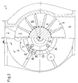
- a cellular wheel sluice 1 has a housing 2 with an inlet 3 and an outlet 4.
- a cellular wheel space 5, in which a cellular wheel 6 is located, is arranged between the inlet 3 and the outlet 4.
- the cellular wheel 6 has a shaft 7 on which webs 8 directed radially outwards are fastened.
- the webs 8 are connected at their axial ends by a flanged wheel 9, so that two adjacent webs 8 together with the flanged wheels 9, the shaft 7 and the housing 1 delimit a cell 10. Bulk material falls into this cell 10 through the inlet 3. When the cell wheel rotates in the direction of arrow 11, the bulk material is transported to the outlet 4. In outlet 4, it falls out of cell 10.
- a sealing ring 13 is provided for each flanged disc 9, which acts on a peripheral surface 12 of the flanged disc 9 .
- the sealing ring 13 is arranged in a housing part 14 in a radial groove 15 and is radially movable there.
- the sealing ring 13 is clamped onto the peripheral surface 12 of the flanged disk 9 by an elastomer bearing 16 arranged in the radial groove.
- the elastomer bearing 16 is closed in a ring.
- the elastomer bearing 16 In operation, it is permanently in contact with both the sealing ring 13 and the base of the radial groove 15. This is achieved in that the elastomer bearing is already preloaded to a predetermined extent in the installation position shown. When relieved, the elastomer bearing 16 can expand, so that the connection between the sealing ring 13 and Because of the radial groove 15 is guaranteed. Conversely, the preload is still so low that further compression of the elastomer bearing 16 is possible. This can be achieved, for example, in that, as in the present exemplary embodiment, the elastomer bearing 16 has an approximately circular cross section in the relaxed state. When pressurized, the material of the elastomer bearing 16 can then escape into the corners of the radial groove 15 that have not yet been filled.
- the friction or the frictional force between the radial groove 15 and the elastomer bearing 16 and also the frictional force between the elastomeric bearing 16 and the sealing ring 13 are greater than the friction between the sealing ring 13 and the peripheral surface 12 of the flanged wheels 9 of the cellular wheel 6. This ensures that the sealing ring 13 in the circumferential direction remains stationary in the housing part 14, in other words it is not taken along when the cell wheel 6 rotates. Wear of the sealing ring 13, which is caused by friction between moving parts, is thus limited to the area that is adjacent to the peripheral surface 12 of the flanged wheels 9.
- a flushing ring Seen from the sealing ring 13, axially inward is a flushing ring in a further radial groove 17 18 arranged. Sealing ring and flushing ring have essentially the same structure. However, a flow path 19 through the sealing ring 18 is provided, which is of helical or helical design. Between the sealing ring 13 and the flushing ring 18, a pressure chamber 20 is formed, which is connected via a channel 21 to a throttle point 22 in the flange 9 with a pressure chamber 23 which is provided on the front side between the flange 9 and the housing 2.
- the shaft 7 has shaft ends 24 on each side.
- Two ball bearings 25, 26 are arranged on each shaft stub 24.
- Each ball bearing has an inner ring 27, 28 and an outer ring 29, 30 and a set of balls 31, 32.
- the inner rings 27, 28 of the ball bearings 25, 26 are attached to the stub shaft 24 without play. For example, they can be shrunk on, pressed on or applied with a suitable fit.
- the outer rings 29, 30 of the ball bearings 25, 26 are displaceable in the axial direction. As a result, the ball bearings 25, 26 can be adjusted without play.
- a ring 33 can be provided, which can be brought to the housing 2 to a greater or lesser extent with the aid of screws 34 which are distributed in the circumferential direction.
- the housing 2 has a slot 35 in the region of the ball bearings.
- Flanges 36, 37 are arranged on both sides of the slot and can be brought together by a threaded bolt 38 or a screw.
- the threaded bolt 38 is tightened, the size of the slot 35 and thus the inner circumference of the housing receiving the outer rings 29, 30 of the ball bearings 25, 26 are also reduced. This allows the outer rings 29, 30 of the ball bearings 25, 26 to be accommodated in the housing 2 without play are.
- the cellular wheel 6 can be stored in the housing 2 without play, at least in the radial direction.
- Two seals 39, 40 and an annular seal 41 are arranged axially inward relative to the ball bearings 25, 26.
- a connection 42 is provided between the seal 40 and the ring seal 41, through which compressed air can be supplied. The compressed air then flows through a gap between the ring seal 41 and the stub shaft 24 into the pressure chamber 23 and builds up a predetermined pressure there.
- the amount of compressed air flowing out is determined by the pressure and the flow resistance, which is caused by the throttle point 20 or the flow path 19.
- the throttle point 22 should be dimensioned so that the pressure in the pressure chamber 20 is only slightly greater than the pressure in the outlet 4. A small flow through the flushing ring 18 is sufficient to carry the particles in again outwards.
- the pressure in the pressure chamber 23 can also be designed to be correspondingly low.
- the pressure difference The sealing ring 13 can therefore be kept very small, so that the sealing ring is not excessively stressed by a pressure difference. Overall, however, the pressure in the pressure chamber 23 is greater than in the inlet 3 or in the outlet 4, so that the sealing ring 13 is in any case only subjected to pressure in one direction.
- a certain amount of air consumption occurs through the air flow from the pressure chamber 23 through the flushing ring 18.
- the flow causes an extremely good cleaning, so that practically no particles can penetrate to the sealing ring 13.
- the service life of the sealing ring 13 is thus increased considerably. Due to the helical course of the flow path 19, on the one hand, a relatively large flow resistance is built up, through which the air losses are kept small. On the other hand, however, it is ensured that the entire axial extent of the flushing ring 18 is regularly cleaned of penetrated particles.
Landscapes
- Engineering & Computer Science (AREA)
- Mechanical Engineering (AREA)
- Sealing Devices (AREA)
- Taps Or Cocks (AREA)
Applications Claiming Priority (2)
| Application Number | Priority Date | Filing Date | Title |
|---|---|---|---|
| DE4214467 | 1992-05-06 | ||
| DE4214467A DE4214467C2 (de) | 1992-05-06 | 1992-05-06 | Zellenradschleuse |
Publications (3)
| Publication Number | Publication Date |
|---|---|
| EP0568950A1 true EP0568950A1 (fr) | 1993-11-10 |
| EP0568950B1 EP0568950B1 (fr) | 1996-07-24 |
| EP0568950B2 EP0568950B2 (fr) | 2000-03-29 |
Family
ID=6457968
Family Applications (1)
| Application Number | Title | Priority Date | Filing Date |
|---|---|---|---|
| EP93107133A Expired - Lifetime EP0568950B2 (fr) | 1992-05-06 | 1993-05-03 | Vanne à roue cellulaire |
Country Status (4)
| Country | Link |
|---|---|
| US (1) | US5392964A (fr) |
| EP (1) | EP0568950B2 (fr) |
| DE (1) | DE4244655C2 (fr) |
| DK (1) | DK0568950T3 (fr) |
Cited By (3)
| Publication number | Priority date | Publication date | Assignee | Title |
|---|---|---|---|---|
| CN103821939A (zh) * | 2013-11-05 | 2014-05-28 | 大连四方佳特流体设备有限公司 | 双密封式回转阀密封机构 |
| CN105253552A (zh) * | 2015-10-20 | 2016-01-20 | 无锡格莱德科技有限公司 | 一种密封旋转阀 |
| EP3456665A1 (fr) * | 2017-04-28 | 2019-03-20 | Rombold & Gfröhrer GmbH & Co. KG | Vanne à roue cellulaire |
Families Citing this family (36)
| Publication number | Priority date | Publication date | Assignee | Title |
|---|---|---|---|---|
| DE4405828A1 (de) * | 1994-02-23 | 1995-08-24 | Krupp Polysius Ag | Zellenradschleuse |
| US5647598A (en) * | 1995-07-19 | 1997-07-15 | Vaudolon; Jean-Pierre | Stuffing box seal having braided packings and lip seal rings in combination with a shaft sleeve |
| US5772081A (en) * | 1996-06-04 | 1998-06-30 | Food Industry Research And Development Institute | Low leakage rotary valve |
| DE19645097A1 (de) * | 1996-11-01 | 1998-05-07 | Motan Fuller Verfahrenstechnik | Zellenradschleuse mit schnellwechselbarer Dichtungsanordnung |
| DE19738122A1 (de) * | 1997-09-01 | 1999-03-11 | Waeschle Maschf Gmbh | Zellenradschleuse zum Dosieren von Schüttgut |
| DE19804431A1 (de) * | 1998-02-05 | 1999-08-12 | Motan Fuller Verfahrenstechnik | Zellenradschleuse mit Zusatzlagerung |
| US6062439A (en) * | 1998-07-07 | 2000-05-16 | Young Industries | Rotary valve with improved sealing means |
| US6454272B1 (en) * | 1999-06-08 | 2002-09-24 | W. S. Shamban Europa A/S | Sealing arrangement and a sealing member therefor |
| US6293439B1 (en) | 2000-07-20 | 2001-09-25 | Chicago Conveyor Corporation | High pressure valve |
| WO2002099320A1 (fr) * | 2001-06-04 | 2002-12-12 | Nok Corporation | Dispositif d'etancheite |
| US7971813B2 (en) * | 2004-07-27 | 2011-07-05 | Owens Corning Intellectual Capital, Llc | Blowing machine for loosefill insulation material |
| US7938348B2 (en) * | 2004-07-27 | 2011-05-10 | Owens Corning Intellectual Capital, Llc | Loosefill blowing machine with a chute |
| US20060024456A1 (en) * | 2004-07-27 | 2006-02-02 | O'leary Robert J | Machine for opening packages of loosefill insulation material |
| US7597219B2 (en) * | 2005-12-16 | 2009-10-06 | Owens Corning Intellectual Capital, Llc | Rotary valve for handling solid particulate material |
| DE102006043252B4 (de) * | 2006-09-11 | 2019-06-19 | Coperion Gmbh | Zellenradschleuse |
| US7845585B2 (en) * | 2006-10-16 | 2010-12-07 | Owens Corning Intellectual Capital, Llc | Blowing wool machine outlet plate assembly |
| US7731115B2 (en) | 2006-10-16 | 2010-06-08 | Owens Corning Intellectual Capital, Llc | Agitation system for blowing insulation machine |
| US7712690B2 (en) * | 2006-10-16 | 2010-05-11 | Owens Corning Intellectual Capital, Llc | Exit valve for blowing insulation machine |
| US7819349B2 (en) * | 2006-10-16 | 2010-10-26 | Owens Corning Intellectual Capital, Llc | Entrance chute for blowing insulation machine |
| US7882947B2 (en) * | 2006-10-16 | 2011-02-08 | Owens Corning Intellectual Capital, Llc | Partially cut loosefill package |
| US7913842B2 (en) * | 2006-10-16 | 2011-03-29 | Owens Corning Intellectual Capital, Llc | Loosefill package for blowing wool machine |
| US7762484B2 (en) * | 2008-04-14 | 2010-07-27 | Owens Corning Intellectual Capital, Llc | Blowing wool machine flow control |
| US7971814B2 (en) * | 2008-12-17 | 2011-07-05 | Owens Corning Intellectual Capital, Llc | Non-symmetrical airlock for blowing wool machine |
| US7886904B1 (en) * | 2009-07-30 | 2011-02-15 | Owens Corning Intellectual Capital, Llc | Loosefill package for blowing wool machine |
| CN101857130B (zh) * | 2010-05-17 | 2015-06-17 | 湖南省三联环保科技有限公司 | 锥形旋转阀 |
| DE102010023237B4 (de) | 2010-06-09 | 2011-12-29 | Jürgen Ulrich | Solarmoduleinheit zur Aufbringung auf einem Flachdach sowie Verfahren zur Fixierung einer Solarmoduleinheit auf einem Flachdach |
| DE202010012138U1 (de) * | 2010-09-02 | 2011-12-12 | Hermann Linder | Zellenradschleuse |
| US9457355B2 (en) | 2011-09-16 | 2016-10-04 | Omachron Intellectual Property Inc. | Apparatus for converting bales of insulation to loose fill |
| DE102012206590A1 (de) * | 2012-04-20 | 2013-10-24 | Coperion Gmbh | Verfahren zum Betrieb einer Zellenradschleuse sowie Zellenradschleuse zur Durchführung des Verfahrens |
| CN102862823A (zh) * | 2012-09-22 | 2013-01-09 | 杭州华新净水有限公司 | 一种密封性能良好的供料阀 |
| MX2017011387A (es) * | 2015-03-06 | 2018-06-07 | Cold Jet Llc | Alimentador de particulas. |
| US10369574B2 (en) | 2015-04-14 | 2019-08-06 | Owens Corning Intellectual Property Capital, LLC | Loosefill insulation blowing machine hose outlet plate assembly |
| US10085376B1 (en) | 2017-03-09 | 2018-10-02 | Cnh Industrial Canada, Ltd. | Meter roller for an agricultural metering system |
| CN107335384A (zh) * | 2017-07-14 | 2017-11-10 | 崇州市四方新能源有限公司 | 便于将生物质颗粒燃料送入传送带的装置 |
| CN109733907B (zh) * | 2019-03-14 | 2024-04-26 | 麦科威(昆山)机械有限公司 | 微型旋转给料阀 |
| CA3152768C (fr) * | 2022-03-17 | 2024-05-28 | Seedmaster Manufacturing Ltd. | Rouleau-doseur de semoir pneumatique avec vidange d'air |
Citations (5)
| Publication number | Priority date | Publication date | Assignee | Title |
|---|---|---|---|---|
| FR2419241A1 (fr) * | 1977-08-02 | 1979-10-05 | Dumont L | Dispositif a sas rotatif pour le transport pneumatique de produits pulverulents |
| US4782741A (en) * | 1984-01-13 | 1988-11-08 | Sigmon James W | Vaneless rotary airlock valve |
| DE8813815U1 (de) * | 1988-11-04 | 1988-12-29 | Andreas Jaudt Dosiertechnik Maschinenfabrik GmbH, 8900 Augsburg | Zellenradschleuse |
| EP0462501A1 (fr) * | 1990-06-20 | 1991-12-27 | Motan Verfahrenstechnik Gmbh & Co. | Ecluse à rotor cellulaire avec étanchéité de fentes pour écluser des matières en vrac dans un convoyeur pneumatique |
| EP0462500A1 (fr) * | 1990-06-20 | 1991-12-27 | Motan Verfahrenstechnik Gmbh & Co. | Carter pour un sas à roue cellulaire |
Family Cites Families (19)
| Publication number | Priority date | Publication date | Assignee | Title |
|---|---|---|---|---|
| CA692378A (en) * | 1964-08-11 | Long George | Rotary valve | |
| US2766911A (en) * | 1951-11-26 | 1956-10-16 | Grenco Inc | Material handling valve |
| US2879094A (en) * | 1957-01-02 | 1959-03-24 | Sherman T Transeau | Peripheral seal assembly |
| US3077272A (en) * | 1958-12-11 | 1963-02-12 | Defibrator Ab | Cell feeder |
| US3052383A (en) * | 1959-12-28 | 1962-09-04 | Sherman T Transeau | Rotary feeder mechanism |
| DE2325624A1 (de) * | 1972-08-28 | 1974-12-12 | Erich Rosenthal | Vorrichtung fuer die zufuhr dosierter mengen von medien zum schmieren und kuehlen rotierender gleitflaechen |
| SE365595B (fr) * | 1972-09-04 | 1974-03-25 | Foerenade Fabriksverken | |
| US3851888A (en) * | 1973-03-21 | 1974-12-03 | A Limpson | Machinery seal |
| US3910428A (en) * | 1973-11-15 | 1975-10-07 | Ii William Donald Peterson | Coal to reactor feeder for coal liquidification |
| US4180188A (en) * | 1975-11-18 | 1979-12-25 | Kokkoman Shoyu Co., Ltd. | Sealing structure for rotary valves |
| CH599487A5 (fr) * | 1976-11-23 | 1978-05-31 | Patent & Inventions Ltd | |
| JPS5740169A (en) * | 1980-08-25 | 1982-03-05 | Toohatsu Kk | Airtight device for rotary valve |
| US4531746A (en) * | 1982-12-10 | 1985-07-30 | Caterpillar Tractor Co. | Dual labyrinth fluid seal with fluid slinger |
| US4565305A (en) * | 1983-05-31 | 1986-01-21 | Koppers Company, Inc. | Rotary vane valve |
| GB2189775B (en) * | 1986-05-01 | 1989-11-29 | Westinghouse Brake & Signal | A rotary valve for granular or particulate material |
| DD260687A1 (de) * | 1987-05-22 | 1988-10-05 | Wissenschaft Und Technik Tabak | Vorrichtung zum ausschleusen schleissender medien, insbesondere unter hoher druckdifferenz arbeitende zellenradschleuse fuer tabakstaub |
| DE3742522C1 (de) * | 1987-12-15 | 1988-11-03 | Waeschle Maschf Gmbh | Zellenradschleuse |
| JPH03195634A (ja) * | 1989-12-22 | 1991-08-27 | Sintokogio Ltd | ロータリーフイーダ装置 |
| GB2246753B (en) * | 1990-07-06 | 1994-03-09 | Waeschle Maschf Gmbh | Rotary bulk material feeder |
-
1992
- 1992-05-06 DE DE4244655A patent/DE4244655C2/de not_active Revoked
-
1993
- 1993-05-03 EP EP93107133A patent/EP0568950B2/fr not_active Expired - Lifetime
- 1993-05-03 DK DK93107133.6T patent/DK0568950T3/da active
- 1993-05-05 US US08/057,991 patent/US5392964A/en not_active Expired - Fee Related
Patent Citations (5)
| Publication number | Priority date | Publication date | Assignee | Title |
|---|---|---|---|---|
| FR2419241A1 (fr) * | 1977-08-02 | 1979-10-05 | Dumont L | Dispositif a sas rotatif pour le transport pneumatique de produits pulverulents |
| US4782741A (en) * | 1984-01-13 | 1988-11-08 | Sigmon James W | Vaneless rotary airlock valve |
| DE8813815U1 (de) * | 1988-11-04 | 1988-12-29 | Andreas Jaudt Dosiertechnik Maschinenfabrik GmbH, 8900 Augsburg | Zellenradschleuse |
| EP0462501A1 (fr) * | 1990-06-20 | 1991-12-27 | Motan Verfahrenstechnik Gmbh & Co. | Ecluse à rotor cellulaire avec étanchéité de fentes pour écluser des matières en vrac dans un convoyeur pneumatique |
| EP0462500A1 (fr) * | 1990-06-20 | 1991-12-27 | Motan Verfahrenstechnik Gmbh & Co. | Carter pour un sas à roue cellulaire |
Non-Patent Citations (1)
| Title |
|---|
| PATENT ABSTRACTS OF JAPAN vol. 6, no. 109 (M-137)(987) 19. Juni 1982 & JP-A-57 040 169 ( TOOHATSU ) 5. März 1982 * |
Cited By (3)
| Publication number | Priority date | Publication date | Assignee | Title |
|---|---|---|---|---|
| CN103821939A (zh) * | 2013-11-05 | 2014-05-28 | 大连四方佳特流体设备有限公司 | 双密封式回转阀密封机构 |
| CN105253552A (zh) * | 2015-10-20 | 2016-01-20 | 无锡格莱德科技有限公司 | 一种密封旋转阀 |
| EP3456665A1 (fr) * | 2017-04-28 | 2019-03-20 | Rombold & Gfröhrer GmbH & Co. KG | Vanne à roue cellulaire |
Also Published As
| Publication number | Publication date |
|---|---|
| DK0568950T3 (da) | 1996-08-26 |
| DE4244655A1 (de) | 1993-11-11 |
| EP0568950B1 (fr) | 1996-07-24 |
| US5392964A (en) | 1995-02-28 |
| DE4244655C2 (de) | 2000-05-31 |
| EP0568950B2 (fr) | 2000-03-29 |
Similar Documents
| Publication | Publication Date | Title |
|---|---|---|
| EP0568950B1 (fr) | Vanne à roue cellulaire | |
| CH684474A5 (de) | Zellenradschleuse mit einer Dichtungsanordnung zwischen der Zellenradseitenscheibe und dem zugehörigen Lagerdeckel. | |
| DE4214467C1 (de) | Zellenradschleuse | |
| EP0462501B1 (fr) | Ecluse à rotor cellulaire avec étanchéité de fentes pour écluser des matières en vrac dans un convoyeur pneumatique | |
| EP0135042B1 (fr) | Dispositif de vanne à tiroir | |
| EP0328737B1 (fr) | Joint d'étanchéité | |
| WO2015124266A1 (fr) | Soupape à tiroir | |
| DE4113738C2 (de) | Zellenradschleuse mit einer Dichtungsanordnung zwischen der Zellenradseitenscheibe und dem zugehörigen Lagerdeckel | |
| EP0329095A1 (fr) | Semoir de précision | |
| DE1525427B1 (de) | Wellendichtung mit zwei Gleichringdichtungen | |
| DE3727173A1 (de) | Durch ein kompressibles fluid, insbesondere pneumatisch schaltbare kupplungs- und bremsvorrichtung | |
| WO1999064164A1 (fr) | Soupape de limitation de debit commandee a precontrainte, en particulier soupape de vaporisation, et barre de vaporisation | |
| CH667705A5 (de) | Dichtungsvorrichtung. | |
| EP0721828A2 (fr) | Camion-bétonnière | |
| EP0411652B1 (fr) | Etanchéité pour tige de vanne | |
| DE19901967A1 (de) | Zellenradschleuse | |
| DE2318995C2 (de) | Ferngesteuertes Ventil für eine Druckluftsandstrahlanlage | |
| EP0560833B1 (fr) | Dispositif pour l'etancheification d'un interstice | |
| DE69210167T2 (de) | Dichtungsring für gleitende Teile, funktionierend bei sehr niedrigen Temperaturen | |
| DE1600708C3 (de) | Druckmittelbetätigter schnellschlieBender Absperrschieber für feststoffführende Leitungen | |
| DE2558651C3 (de) | Wellendichtung mit einem mit der Welle umlaufenden Dichtring | |
| DE3843288A1 (de) | Gleitringdichtung | |
| DE102023206882B3 (de) | Dichtungsanordnung und Baugruppe für die Schüttgut-Förderung mit einer derartigen Dichtungsanordnung | |
| DE9407733U1 (de) | Dichtungsanordnung | |
| DE3222728C2 (fr) |
Legal Events
| Date | Code | Title | Description |
|---|---|---|---|
| PUAI | Public reference made under article 153(3) epc to a published international application that has entered the european phase |
Free format text: ORIGINAL CODE: 0009012 |
|
| AK | Designated contracting states |
Kind code of ref document: A1 Designated state(s): CH DK FR IT LI NL |
|
| 17P | Request for examination filed |
Effective date: 19931013 |
|
| 17Q | First examination report despatched |
Effective date: 19941107 |
|
| GRAH | Despatch of communication of intention to grant a patent |
Free format text: ORIGINAL CODE: EPIDOS IGRA |
|
| GRAH | Despatch of communication of intention to grant a patent |
Free format text: ORIGINAL CODE: EPIDOS IGRA |
|
| GRAA | (expected) grant |
Free format text: ORIGINAL CODE: 0009210 |
|
| AK | Designated contracting states |
Kind code of ref document: B1 Designated state(s): CH DK FR IT LI NL |
|
| ITF | It: translation for a ep patent filed | ||
| REG | Reference to a national code |
Ref country code: CH Ref legal event code: NV Representative=s name: PATENTANWALTSBUREAU BOSSHARD UND LUCHS |
|
| REG | Reference to a national code |
Ref country code: DK Ref legal event code: T3 |
|
| ET | Fr: translation filed | ||
| PLBI | Opposition filed |
Free format text: ORIGINAL CODE: 0009260 |
|
| 26 | Opposition filed |
Opponent name: BUEHLER AG Effective date: 19961205 |
|
| NLR1 | Nl: opposition has been filed with the epo |
Opponent name: BUEHLER AG |
|
| PLBQ | Unpublished change to opponent data |
Free format text: ORIGINAL CODE: EPIDOS OPPO |
|
| PLBI | Opposition filed |
Free format text: ORIGINAL CODE: 0009260 |
|
| PGFP | Annual fee paid to national office [announced via postgrant information from national office to epo] |
Ref country code: DK Payment date: 19970520 Year of fee payment: 5 |
|
| PGFP | Annual fee paid to national office [announced via postgrant information from national office to epo] |
Ref country code: FR Payment date: 19970523 Year of fee payment: 5 |
|
| PLBF | Reply of patent proprietor to notice(s) of opposition |
Free format text: ORIGINAL CODE: EPIDOS OBSO |
|
| PGFP | Annual fee paid to national office [announced via postgrant information from national office to epo] |
Ref country code: NL Payment date: 19970531 Year of fee payment: 5 |
|
| 26 | Opposition filed |
Opponent name: WAESCHLE MASCHINENFABRIK GMBH Effective date: 19970424 Opponent name: BUEHLER AG Effective date: 19961205 |
|
| NLR1 | Nl: opposition has been filed with the epo |
Opponent name: WAESCHLE MASCHINENFABRIK GMBH Opponent name: BUEHLER AG |
|
| PLBF | Reply of patent proprietor to notice(s) of opposition |
Free format text: ORIGINAL CODE: EPIDOS OBSO |
|
| PLBF | Reply of patent proprietor to notice(s) of opposition |
Free format text: ORIGINAL CODE: EPIDOS OBSO |
|
| PG25 | Lapsed in a contracting state [announced via postgrant information from national office to epo] |
Ref country code: FR Free format text: LAPSE BECAUSE OF NON-PAYMENT OF DUE FEES Effective date: 19980531 Ref country code: DK Free format text: LAPSE BECAUSE OF NON-PAYMENT OF DUE FEES Effective date: 19980531 |
|
| PG25 | Lapsed in a contracting state [announced via postgrant information from national office to epo] |
Ref country code: NL Free format text: LAPSE BECAUSE OF NON-PAYMENT OF DUE FEES Effective date: 19981201 |
|
| NLV4 | Nl: lapsed or anulled due to non-payment of the annual fee |
Effective date: 19981201 |
|
| REG | Reference to a national code |
Ref country code: FR Ref legal event code: ST |
|
| PLAW | Interlocutory decision in opposition |
Free format text: ORIGINAL CODE: EPIDOS IDOP |
|
| PLAW | Interlocutory decision in opposition |
Free format text: ORIGINAL CODE: EPIDOS IDOP |
|
| PUAH | Patent maintained in amended form |
Free format text: ORIGINAL CODE: 0009272 |
|
| REG | Reference to a national code |
Ref country code: DK Ref legal event code: EBP |
|
| 27A | Patent maintained in amended form |
Effective date: 20000329 |
|
| AK | Designated contracting states |
Kind code of ref document: B2 Designated state(s): CH DK FR IT LI NL |
|
| REG | Reference to a national code |
Ref country code: CH Ref legal event code: AEN Free format text: AUFRECHTERHALTUNG DES PATENTES IN GEAENDERTER FORM |
|
| EN | Fr: translation not filed | ||
| K2C3 | Correction of patent specification (complete document) published |
Effective date: 20000329 |
|
| PG25 | Lapsed in a contracting state [announced via postgrant information from national office to epo] |
Ref country code: IT Free format text: LAPSE BECAUSE OF NON-PAYMENT OF DUE FEES;WARNING: LAPSES OF ITALIAN PATENTS WITH EFFECTIVE DATE BEFORE 2007 MAY HAVE OCCURRED AT ANY TIME BEFORE 2007. THE CORRECT EFFECTIVE DATE MAY BE DIFFERENT FROM THE ONE RECORDED. Effective date: 20050503 |
|
| PGFP | Annual fee paid to national office [announced via postgrant information from national office to epo] |
Ref country code: CH Payment date: 20050825 Year of fee payment: 13 |
|
| PG25 | Lapsed in a contracting state [announced via postgrant information from national office to epo] |
Ref country code: LI Free format text: LAPSE BECAUSE OF NON-PAYMENT OF DUE FEES Effective date: 20060531 Ref country code: CH Free format text: LAPSE BECAUSE OF NON-PAYMENT OF DUE FEES Effective date: 20060531 |
|
| REG | Reference to a national code |
Ref country code: CH Ref legal event code: PL |
|
| PGFP | Annual fee paid to national office [announced via postgrant information from national office to epo] |
Ref country code: IT Payment date: 20070522 Year of fee payment: 15 |
|
| PGRI | Patent reinstated in contracting state [announced from national office to epo] |
Ref country code: IT Effective date: 20091201 |
|
| PGRI | Patent reinstated in contracting state [announced from national office to epo] |
Ref country code: IT Effective date: 20091201 |